XIAO ESP32S3 Deep Sleep

Hi, I am working on a water quality monitoring system and I am interfacing to some sensors however this only needs to be done periodically so I thought I would put the system into deep sleep when the sensors do not need to be read. I am using the XIAO Expansion Board and the XIAO ESP32S3 and to test the current pull I have the esp32 plugged into a bread board, with all the connections going into the xiao expansion board. I have disconnected the 3V3 from both and connect them via the multimeter in between so I can measure the current draw. I am using 1 digital in pin, as well as an I2C to read my sensors. I am drawing around 50mA of current when the sensors are being read which happens under a second however when in deep sleep, I seem to only drop around 1-2 mA so it hovers around the 48mA range. I was expecting a much lower drop for deep sleep. I am unsure I have my setup incorrect or my code. Any advice will be greatly appreciated. I have attached a view images of my setup and the code I am using.

#include <Arduino.h>       // Include Arduino core library
#include <U8x8lib.h>       // Include U8x8 library for OLED display
#include <Wire.h>          // Include Wire library for I2C communication
#include <string.h>        // Include the library to work with strings
#include <cstring>         // For strlen, strncpy, etc.

#include "SensorReader.h"  // Include the sensor reading library
#include "SensorStruct.h"  // Include the struct that holds all the sensor data

// Define constants for pin assignments
const int TEMP_WIRE_BUS = 1;    // GPIO 1

SensorData sensorData;          // Create an instance of SensorData
SensorReader sensorRead(TEMP_WIRE_BUS);    // Create an instance of the sensor reader 

#define uS_TO_S_FACTOR 1000000ULL  /* Conversion factor for micro seconds to seconds */
#define TIME_TO_SLEEP  60        /* Time ESP32 will go to sleep (in seconds) */

RTC_DATA_ATTR int bootCount = 0;


void print_wakeup_reason(){
  esp_sleep_wakeup_cause_t wakeup_reason;

  wakeup_reason = esp_sleep_get_wakeup_cause();

  switch(wakeup_reason)
  {
    case ESP_SLEEP_WAKEUP_EXT0 : Serial.println("Wakeup caused by external signal using RTC_IO"); break;
    case ESP_SLEEP_WAKEUP_EXT1 : Serial.println("Wakeup caused by external signal using RTC_CNTL"); break;
    case ESP_SLEEP_WAKEUP_TIMER : Serial.println("Wakeup caused by timer"); break;
    case ESP_SLEEP_WAKEUP_TOUCHPAD : Serial.println("Wakeup caused by touchpad"); break;
    case ESP_SLEEP_WAKEUP_ULP : Serial.println("Wakeup caused by ULP program"); break;
    default : Serial.printf("Wakeup was not caused by deep sleep: %d\n",wakeup_reason); break;
  }
}


void setup(){
  Serial.begin(115200);
  delay(1000); //Take some time to open up the Serial Monitor

  //Increment boot number and print it every reboot
  ++bootCount;
  Serial.println("Boot number: " + String(bootCount));

  //Print the wakeup reason for ESP32
  print_wakeup_reason();

  sensorRead.initialise();           // Initialise the sensors
  sensorRead.readSensorValues(sensorData);  // Read sensor data
  sensorRead.printData(sensorData);        // Print the data for debugging

  esp_sleep_enable_timer_wakeup(TIME_TO_SLEEP * uS_TO_S_FACTOR);
  Serial.println("Setup ESP32 to sleep for every " + String(TIME_TO_SLEEP) +
  " Seconds");

  Serial.println("Going to sleep now");
  Serial.flush(); 
  esp_deep_sleep_start();
  Serial.println("This will never be printed");
}

void loop(){
  //This is not going to be called
}


Hi there,
So that’s not gonna fly, Are you Powering the Expansion board by the Xiao’s USB-c ?
To get a true reading you need to use the Battery Pads on the bottom to power it, Disconnect the USB-c connection and power the expansion board with the battery also.
A couple things are at play here.
Look at the schematic of both the xiao and the Expansion board.
ALso are you using deep sleep or light sleep? more steps would be required to power off other devices like PSram and Flash sleep?
I can try it without the sensors and just the sleep current with the PPKII report what I see.
HTH
GL :slight_smile: PJ

40ma running , 20uA sleeping

here’s the connections & code used.

#include <Arduino.h>       // Include Arduino core library
#include <U8x8lib.h>       // Include U8x8 library for OLED display
#include <Wire.h>          // Include Wire library for I2C communication
#include <string.h>        // Include the library to work with strings
#include <cstring>         // For strlen, strncpy, etc.
#include <Adafruit_Sensor.h>
//#include "SensorReader.h"  // Include the sensor reading library
//#include "SensorStruct.h"  // Include the struct that holds all the sensor data

// Define constants for pin assignments
const int TEMP_WIRE_BUS = 1;    // GPIO 1
sensor_t sensorData;
//SensorData sensorData;          // Create an instance of SensorData
//SensorReader sensorRead(TEMP_WIRE_BUS);    // Create an instance of the sensor reader 

#define uS_TO_S_FACTOR 1000000  /* Conversion factor for micro seconds to seconds */
#define TIME_TO_SLEEP  50        /* Time ESP32 will go to sleep (in seconds) */

RTC_DATA_ATTR int bootCount = 0;

int LED_pin = 21;

void print_wakeup_reason(){
  esp_sleep_wakeup_cause_t wakeup_reason;

  wakeup_reason = esp_sleep_get_wakeup_cause();

  switch(wakeup_reason)
  {
    case ESP_SLEEP_WAKEUP_EXT0 : Serial.println("Wakeup caused by external signal using RTC_IO"); break;
    case ESP_SLEEP_WAKEUP_EXT1 : Serial.println("Wakeup caused by external signal using RTC_CNTL"); break;
    case ESP_SLEEP_WAKEUP_TIMER : Serial.println("Wakeup caused by timer"); break;
    case ESP_SLEEP_WAKEUP_TOUCHPAD : Serial.println("Wakeup caused by touchpad"); break;
    case ESP_SLEEP_WAKEUP_ULP : Serial.println("Wakeup caused by ULP program"); break;
    default : Serial.printf("Wakeup was not caused by deep sleep: %d\n",wakeup_reason); break;
  }
}


void setup(){
  Serial.begin(115200);
  delay(3000); //Take some time to open up the Serial Monitor
    Serial.println("Processor came out of reset.");
  Serial.println();
pinMode(LED_pin, OUTPUT);
  //Increment boot number and print it every reboot
  ++bootCount;
  Serial.println("Boot number: " + String(bootCount));
// turn on:
    digitalWrite(LED_pin, HIGH);
    delay(2000);
    digitalWrite(LED_pin, LOW);
    delay(2000);
    digitalWrite(LED_pin, HIGH);
    delay(2000);
    digitalWrite(LED_pin, LOW);
    delay(2000);
    digitalWrite(LED_pin, HIGH);
    delay(2000);
  //Print the wakeup reason for ESP32
  print_wakeup_reason();

  //sensorRead.initialise();           // Initialise the sensors
  //sensorRead.readSensorValues(sensorData);  // Read sensor data
 // sensorRead.printData(sensorData);        // Print the data for debugging
esp_sleep_enable_timer_wakeup(50 * 1000000); // Set wake-up time to 60 seconds
  //esp_sleep_enable_timer_wakeup(TIME_TO_SLEEP * uS_TO_S_FACTOR);
  Serial.println("Setup ESP32 to sleep for every " + String(TIME_TO_SLEEP) +
  " Seconds");

  Serial.println("Going to sleep now");
  //Serial.flush(); 
  // turn on:
    //digitalWrite(LED_pin, LOW);
  esp_deep_sleep_start();
 // delay (250);
 //Serial.println("This will never be printed");
}

void loop(){
  //This is not going to be called
delay(250);
}

serial output , Notice the wake up cause :grinning: :+1:

21:31:41.866 -> Processor came out of reset.
21:31:41.866 -> 
21:31:41.866 -> Boot number: 2
21:31:51.915 -> Wakeup caused by timer
21:32:54.950 -> Processor came out of reset.
21:32:54.950 -> 
21:32:54.950 -> Boot number: 3
21:33:04.956 -> Wakeup caused by timer
21:33:04.956 -> Setup ESP32 to sleep for every 50 Seconds
21:33:04.956 -> Going to sleep now
21:34:08.039 -> Processor came out of reset.
21:34:08.039 -> 
21:34:08.039 -> Boot number: 4
21:34:18.040 -> Wakeup caused by timer
21:34:18.040 -> Setup ESP32 to sleep for every 50 Seconds
21:34:18.040 -> Going to sleep now
21:35:21.172 -> Processor came out of reset.

I added the LED on/Off because when nothing but battery is connected you can’t tell if it’s on or asleep :smiley:

HTH
GL :slight_smile: PJ

Hi,
Thanks for the help, I was powering using the USB-C. I can power it using the battery connected to the expansion board, but I am uncertain where to measure the power on the expansion board, or will I have to still solder some wires to the underside of the xiao and measure the power like that

I only have access to a multimeter atm but next week I am going back to uni so I will have access to an oscilloscope to make more accurate readings.

And just for clarity I was planning to use the JST pins found on the xiao expansion board to power the board

Hi there,
Yes the JST connector powers the Expansion board and Xiao if plugged in. Connected directly on BAT pads on bottom is the only way to measure the true power draw of Xiao. to measure in Line with a multimeter is fine. (I used the PPK2)
The Power Ninja :ninja: Msfujino has a thread on here and is on the wiki for measuring the Bat. Voltage of the Xiao(adds a voltage divider resistors to board) check those for additional info.

HTH
GL :slight_smile: PJ :v:

Hi, Perfect thanks for the help, I shall try and implement that today.

Thanks, for the help

1 Like

I am also thinking of picking up a PPK2 as I have heard great things about it, and the best thing is that it works on a mac which is essential since that is what I use :slight_smile:

Hi there,
Yes 100% PPK2 does it all, and has 8/10 channels logic scope too.
That and the 10$ Dongle you can’t go wrong, best $99 bucs I’ve spent for a Great tool, not to mention the software and Nordics support. (waiting on my free shirt) :grinning: :+1:
Nrf Connect for desktop has it all in one single place, easy to use & find help.
HTH
GL :slight_smile: PJ

Check it…

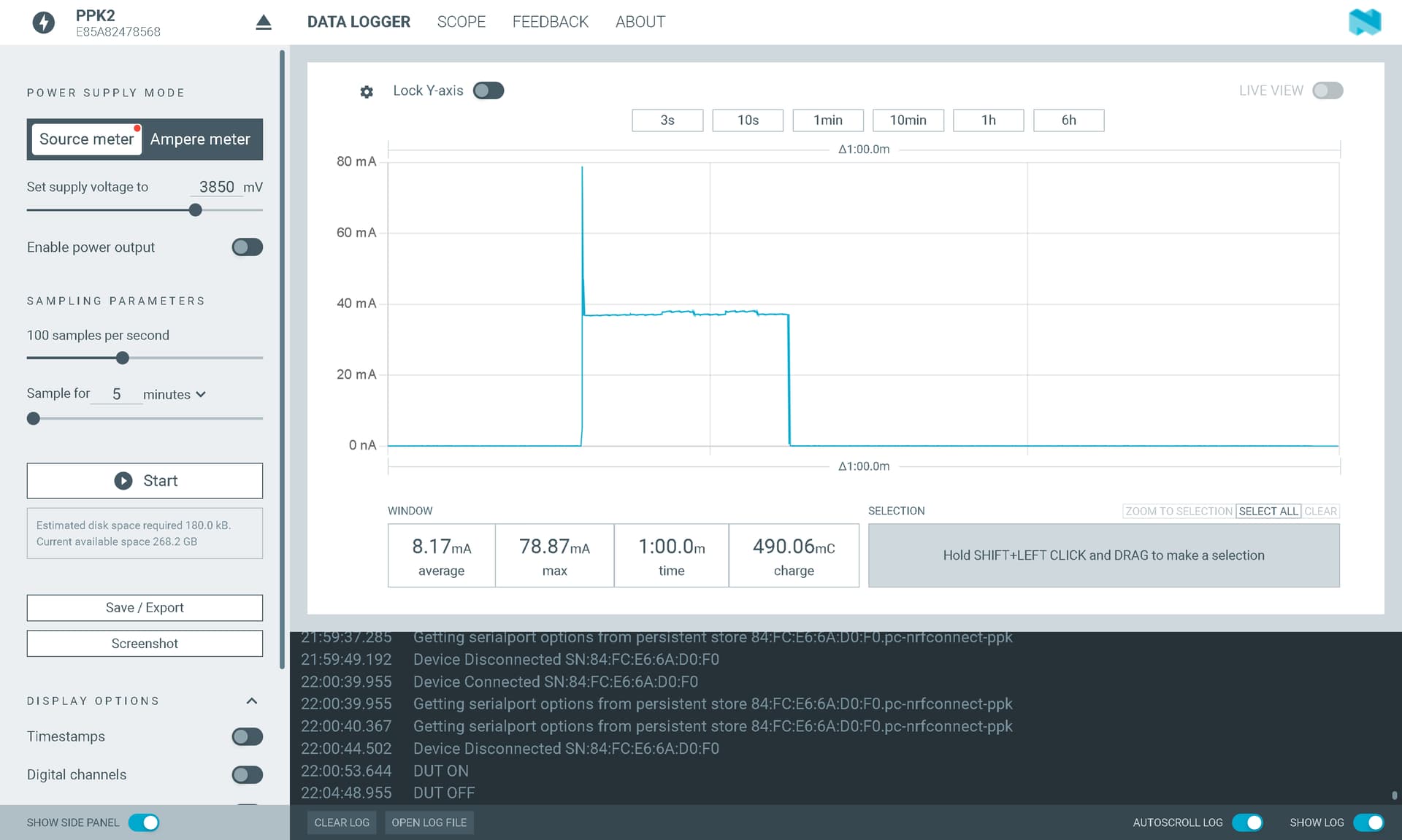
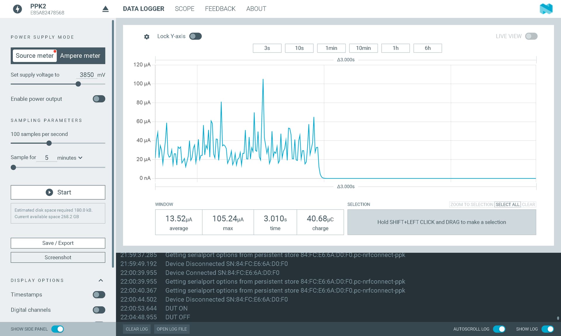
I was wondering if there is a way to disable certain pins on the esp32 such as my i2c and uart pins as during deep sleep, they are still pulling current which is not ideal. I have tried using rtc_gpio_isolate and. disabling the pullup and pulldown pins and I am just getting really confused. Any advice will be appreciated, I have attached my code below:

#include <Arduino.h>
#include <U8x8lib.h>
#include <Wire.h>
#include <string.h>
#include <cstring>

#include "GPSManager.h"
#include "SDManager.h"
#include "SensorReader.h"
#include "SensorStruct.h"

// Minimum GPS accuracy required for data recording
const int GPS_ACCURACY = 6;

// Set to true to enable GPSECHO for debugging
#define GPSECHO false

// Pin definitions
const uint8_t BUTTON_PIN = 2;
const int SD_CARD_PIN = 3;
const int SD_CARD_CS_PIN = D2;
const int TEMP_WIRE_BUS = 1;

// Constants for LoRaWAN configuration
static char recv_buf[512];
static bool is_exist = false;
static bool is_join = false;

// Initialize manager objects
GPSManager gpsManager;
SDManager sdManager(SD_CARD_PIN, SD_CARD_CS_PIN);
SensorData sensorData;
SensorReader sensorReader(TEMP_WIRE_BUS);

// RTC-backed variables for persistent storage
RTC_DATA_ATTR unsigned int bootCount = 0;
RTC_DATA_ATTR char dataBuffer[1000];
RTC_DATA_ATTR unsigned int bufferIndex = 0;
RTC_DATA_ATTR unsigned int bufferWriteCount = 0;

// Conversion factors for sleep timing, GPS Timeout and Buffer for SD Card
#define CONVERT_S_TO_US 1000000ULL
#define CONVERT_M_TO_S  60
#define CONVERT_H_TO_S  3600
#define CONVERT_D_TO_S  86400
#define GPS_TIME_LOCK 120000
#define BUFFER_THRESHOLD 0.7
#define TIME_TO_SLEEP  30

RTC_DATA_ATTR unsigned long long sleepDuration = TIME_TO_SLEEP * CONVERT_S_TO_US;

// Function to send AT commands to the LoRaWAN module and check the response
static int at_send_check_response(const char* expected_ack, int timeout_ms, const char* command_format, ...)
{
  memset(recv_buf, 0, sizeof(recv_buf));

  // Print the command to both Serial1 and Serial
  va_list args;
  va_start(args, command_format);
  Serial1.printf(command_format, args);
  Serial.printf(command_format, args);
  va_end(args);

  // Wait a short delay for the command to be sent
  delay(200);

  // If no expected_ack, return immediately
  if (expected_ack == nullptr)
  {
      return 0;
  }

  // Read the response from Serial1 and check for the expected_ack
  unsigned long start_time = millis();
  while (millis() - start_time < timeout_ms)
  {
      while (Serial1.available() > 0)
      {
          recv_buf[strlen(recv_buf)] = static_cast<char>(Serial1.read());
          // Serial.print(recv_buf[strlen(recv_buf) - 1]);
          delay(2);
      }
      if (strstr(recv_buf, expected_ack) != nullptr)
      {
          return 1;
      }
  }

  // Timeout reached without finding the expected_ack
  return 0;
}

// Function to parse the received data from the LoRaWAN module
static void recv_parse(char *message, SensorData& sensorData)
{
  if (message == NULL)
  {
    return;
  }

  int port = 0;
  unsigned long timing = 0;
  int rssi = 0; 
  int snr = 0;
  
  // Parse the port number from the received message
  char *start = strstr(message, "PORT:");
  if (start && (1 == sscanf(start, "PORT: %d;", &port)))
  {
    // Parse the timing value from the received message
    start = strstr(message, "RX:");
    if (start && (1 == sscanf(start, "RX: \"%lx\"", &timing)))
    {
      // Go through the different ports which indicate a different timing slot
      switch (port)
      {
        case 1:
          // Convert to minutes
          sleepDuration = timing * CONVERT_M_TO_S * CONVERT_S_TO_US;
          break;
        case 2:
          // Convert to hours
          sleepDuration = timing * CONVERT_H_TO_S * CONVERT_S_TO_US;
          break;
        case 3:
          sleepDuration = timing * CONVERT_D_TO_S * CONVERT_S_TO_US;
          break;
      }
    }
  }
  
  // Parse the RSSI value from the received message
  start = strstr(message, "RSSI");
  if (start && (1 == sscanf(start, "RSSI %d,", &rssi)))
  {
    sensorData.rssi = rssi;
  }

  // Parse the SNR value from the received message
  start = strstr(message, "SNR");
  if (start && (1 == sscanf(start, "SNR %d", &snr)))
  {
    sensorData.snr = snr;
  }
}

// Method to initialize LoRaWAN module and configure parameters
bool initaliseLoRaWAN()
{ 
  // Check if E5 Module exists
  if(at_send_check_response("+AT: OK", 100, "AT\r\n"))
  {
    // Configure LoRaWAN parameters
    const int TIMEOUT_SHORT = 1000;
    const int TIMEOUT_LONG = 12000;

    // Configure parameters
    at_send_check_response("+ID:", TIMEOUT_SHORT, "AT+ID\r\n");           // Get device ID
    at_send_check_response("+MODE: LWOTAA", TIMEOUT_SHORT, "AT+MODE=LWOTAA\r\n");   // Select LoRaWAN mode
    at_send_check_response("+DR: EU868", TIMEOUT_SHORT, "AT+DR=EU868\r\n"); // Select frequency band
    at_send_check_response("+CH: NUM", TIMEOUT_SHORT, "AT+CH=NUM,0-2\r\n"); // Select sub band
    at_send_check_response("+ID: DevEui", TIMEOUT_SHORT, "AT+ID=DevEui,\"70B3D57ED00655FB\"\r\n");  // Write device EUI
    at_send_check_response("+ID: AppEui", TIMEOUT_SHORT, "AT+ID=AppEui,\"0128944F83E7AF55\"\r\n");  // Write application EUI
    at_send_check_response("+KEY: APPKEY", TIMEOUT_SHORT, "AT+KEY=APPKEY,\"7A48DD0E7F43A8FC53A5F018087C9508\"\r\n");  // Write application key
    at_send_check_response("+CLASS: C", TIMEOUT_SHORT, "AT+CLASS=A\r\n"); // Write device class
    at_send_check_response("+PORT: 8", TIMEOUT_SHORT, "AT+PORT=8\r\n");   // Set port number
    at_send_check_response("+ADR: ON", TIMEOUT_SHORT, "AT+ADR=ON\r\n");   // Enable Adaptive Data Rate

    // Delay for stability
    delay(200);

    // Attempt to join the LoRaWAN network
    return at_send_check_response("+JOIN: Network joined", TIMEOUT_LONG, "AT+JOIN\r\n");
  }
  
  // If the LoRa Module cannot be seen, return false
  return false;
}

bool sendDataOverLoRaWAN(SensorData& sensorData)
{
  // Convert sensor values to integers for transmission
  int temp_int = static_cast<uint32_t>(sensorData.temp * 10);
  int ph_int = static_cast<uint8_t>(sensorData.ph * 10);
  int tds_int = static_cast<uint16_t>(sensorData.tds * 100);
  int turbidity_int = static_cast<uint16_t>(sensorData.turbidity * 100);
  int ir_int = static_cast<uint16_t>(sensorData.ir);
  int visible_int = static_cast<uint16_t>(sensorData.visible);
  int latitude_int = static_cast<uint64_t>(sensorData.latitude * 1000000);
  int longitude_int = static_cast<uint64_t>(sensorData.longitude * 1000000);
  int speed_int = static_cast<uint16_t>(sensorData.speed * 100);
  int angle_int = static_cast<uint16_t>(sensorData.angle * 100);
  int altitude_int = static_cast<uint16_t>(sensorData.altitude * 100);
  int satellites_int = sensorData.satellites;
  int fix_int = sensorData.fix;
  int quality_int = sensorData.quality;

  // Construct the uplink message in hexadecimal format
  char uplink[128];
  sprintf(uplink, "AT+CMSGHEX=\"%08X%02X%04X%04X%04X%04X%016X%016X%04X%04X%04X%02X%02X%02X\"\r\n",
          temp_int, ph_int, tds_int, turbidity_int, ir_int, visible_int,
          latitude_int, longitude_int, speed_int, angle_int, altitude_int, satellites_int, fix_int, quality_int);

  // Check if the uplink has gone through. Will always come back with a fail
  at_send_check_response("Done", 5000, uplink);

  // Send a zero-length payload to allow the downlink to be read
  char downlink[128];
  sprintf(downlink, "AT+CMSGHEX");

  if (at_send_check_response("Done", 12000, downlink))
  {
    recv_parse(recv_buf, sensorData);
    return true;    // If the Data has been sent return true
  }

  return false;   // If the Data has not been sent return false
}

// Function to add data to the buffer and write to the SD card if necessary
void addToBufferAndWriteToFile(const String& dataString)
{
  size_t availableSpace = sizeof(dataBuffer) - bufferIndex - 1;

  // If buffer is full or dataString cannot fit in the remaining space
  if (bufferWriteCount >= BUFFER_THRESHOLD * 100 || dataString.length() > availableSpace)
  {
    resetBuffer(); // Write buffer to SD card and reset
  }

  // Determine how much of dataString can fit in the remaining space
  size_t copyLength = min(dataString.length(), availableSpace);

  // Copy dataString to buffer
  strncpy(dataBuffer + bufferIndex, dataString.c_str(), copyLength);
  bufferIndex += copyLength;
  dataBuffer[bufferIndex++] = '\n'; // Add newline
  dataBuffer[bufferIndex] = '\0'; // Null terminate the string

  // Increment buffer write count
  bufferWriteCount++;
}

// Function to write the buffer to the SD card and reset the buffer
void resetBuffer()
{
  const char* DATA_FILE_PATH = "/SensorData.txt";
  sdManager.initialise();
  bool written = sdManager.writeToFile(DATA_FILE_PATH, dataBuffer);

  if (written)
  {
    memset(dataBuffer, 0, sizeof(dataBuffer));
    bufferIndex = 0;
    bufferWriteCount = 0;
  } else
  {
    size_t copyLength = bufferIndex; // Keep track of current data length

    // Check if there's enough space to accommodate both existing and new data
    if (copyLength + bufferIndex < sizeof(dataBuffer))
    {
      // Shift existing data to make room for new data
      memmove(dataBuffer, dataBuffer + copyLength, sizeof(dataBuffer) - copyLength);
      
      // Reset buffer index and write count
      bufferIndex = copyLength;
      bufferWriteCount++;
    } else
    {
      // Handle case where buffer is not large enough to accommodate both data
      // For simplicity the buffer is cleared
      bufferIndex = 0;
      bufferWriteCount = 0;
    }
  }
}

void setup() {
  // Take some time to open up the Serial Monitor
  Serial.begin(115200);
  delay(1000);

  // Begin serial communication to allow for LoRa communication
  Serial1.begin(9600, SERIAL_8N1, 44, 43);

  //Initialise the sensors
  Wire.begin();
  sensorReader.initialise();
  gpsManager.setup();
  
  ++bootCount;
  Serial.println("Boot number: " + String(bootCount));
  
  unsigned long startTime = millis(); // Get the start time
  
  // Wait for GPS to acquire satellites
  while (sensorData.satellites == 0.0)
  {
    gpsManager.update(sensorData);
    
    // Check if 2 minutes have elapsed
    if (millis() - startTime >= GPS_TIME_LOCK)
    {
      //Satellite search timed out
      break; // Exit the loop if 2 minutes have elapsed
    }
  }
  
  // Read sensor values
  sensorReader.readSensorValues(sensorData);

  // Attempt to initialize LoRaWAN module and send data if initialization succeeds
  sensorData.loraSent = initaliseLoRaWAN() && sendDataOverLoRaWAN(sensorData);

  String dataString = sensorReader.getSensorValuesAsString(sensorData);
  addToBufferAndWriteToFile(dataString);
  Serial.println(dataBuffer);

  // Disable the I2C, UART, and other RTC peripherals before going to sleep
  esp_sleep_pd_config(ESP_PD_DOMAIN_RTC_PERIPH, ESP_PD_OPTION_OFF);
  
  // Enable deep sleep mode
  esp_sleep_enable_timer_wakeup(sleepDuration);
  Serial.println("Going to sleep for " + String(sleepDuration / CONVERT_S_TO_US) + " seconds");
  Serial.flush();
  esp_deep_sleep_start();
}

void loop()
{
  // This loop is empty as the device will be in deep sleep mode
}

HI there,
Yes there is some nuance required when dealing with the GPIO’s for power down and current flow through (Sinked) pull-Ups or Down resistors. like the I2C pins.

Configuring IOs (Deep-sleep Only)

Some ESP32-S3 IOs have internal pullups or pulldowns, which are enabled by default. If an external circuit drives this pin in Deep-sleep mode, current consumption may increase due to current flowing through these pullups and pulldowns.

To isolate a pin to prevent extra current draw, call rtc_gpio_isolate() function.

For example, on ESP32-WROVER module, GPIO12 is pulled up externally, and it also has an internal pulldown in the ESP32 chip. This means that in Deep-sleep, some current flows through these external and internal resistors, increasing Deep-sleep current above the minimal possible value.

Add the following code before esp_deep_sleep_start() to remove such extra current:

rtc_gpio_isolate(GPIO_NUM_12);

The XIAO ESP32S3 it would be GPIO5(A4) & GPIO6(A5)
give that a go.
GL :slight_smile: PJ