Xiao esp32C6 and the DS18B20

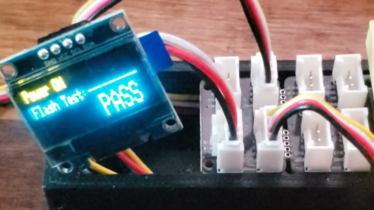
I’m using the Xiao above (C6) mounted on the cool expansion board with the tiny display in the middle. I want to measure temperature with an 18B20 using the recommended Arduino IDE. So, I loaded the Dallas and One Wire libraries, and of course, it wouldn’t compile. So, I chased down the error and put the newest .h file in the One Wire library directory and it compiled, but it didn’t work.

I took the code example that everyone uses the first time, used pin 7 as the bus, and all I got back was the default -127 and -196 that usually indicates that the code didn’t see the 18B20.

So, I hunted the web looking for solutions and found another library, OneWireNg and loaded it. It compiled first time, but it didn’t work either. Same results.

So, I tried another sensor, same results. Then,instead of the waterproof sensor I want to use, I used one of the little ones, same results. In desperation, I chased the wires from the grove plug I used to the actual wires on the side of the C6 board. They checked out fine.

Yes, I have the resistor from 3.3 to the data line; that was the first thing I did.

Now, I may be a newby to the C6, but I’m not new to the 18B20, I’ve installed those things on a lot of devices to monitor temperatures from the heat sink on a large battery charger to the one inside my freezer; I have them controlling my A/C units. They ALL worked first try.

Not this time. Two different libraries and multiple sensors, same results. I even moved the 18B20 to pin 0 to see if that made a difference, same results.

What am I missing? Is there some secret to using one wire on the C6 that I missed in my hours of searching for answers. This really shouldn’t be hard.

I have the sensors, dozens of them in a bag (Digi had a sale a few years back). Both the waterproof ones and the little ones. I use them all the time with various little processors.

BUT I FOUND THE PROBLEM !!

After hours and hours of trying things, while I was typing in the question and describing the problem, I thought of something that I hadn’t tried, and absolutely none of the examples out there had in them. I tried it, and it worked.

I changed the code from this:

void setup() {
// Start the Serial Monitor
Serial.begin(115200);
// Start the DS18B20 sensor
sensors.begin();
}

to this:

void setup() {
// Start the Serial Monitor
Serial.begin(115200);
// Start the DS18B20 sensor
pinMode(oneWireBus, INPUT);
sensors.begin();
}

Yep, I had to let the device know what I was using the pin for. I have the pin (oneWireBus) defined as D7, not 7. None of the examples, tutorials, etc have this little jewel in them. That makes me wonder how many people actually do the things they spout off about on the web. It also make me wonder how many people try some of those things and just give up after trying for a couple of hours.

3 Likes

yes the BSP Board Support Package and excessivly high baud rate are usually the problem

How is that a factor?

the BSP controls how the pins are mapped… what physical pin goes to which gpio… each XIAO model had a different mapping scheme… the BSP works in the background to do this mapping… so for example if you use pin D7 with the board support package loaded for a XIAO ESP32s3 instead of an Esp32C3 all betts are off… D7 is not a real pin… it is a representation of a location on the board and a “variable” for lack of a better word in the code. If you multiply axb=c you cannot expect to get the same answer if you multiply exf=g will never ever work excessivly high baudrate will cause the XIAO to not accept new code upload without hard boot-reset and can be a pain in the A… also fast or slow baud can effect waste of processor respurces and interupt problems

So, if I had waited to initialize the serial port until after the one wire bus, it might have worked? Or maybe put a small delay between the the two it might have worked. I can test those items pretty easily. However, there was nothing going on at the time those things were happening. The board init should have finished before setup() was called, and just setting the baud rate shouldn’t interfere.

I may go back now and test the other libraries I tried (if I can remember them) and see if they work as well.

1 Like

Hi there,

So the BSP is only compatable with certain LIBs, more than likely the One wire is Older and requires an older BSP. also I have an example code with compiler output as well , so you can see which versions worked for the Xmas Demo I have on here. I used the DS18B20 code is included. Gove Expansion board demo.

HTH

GL :slight_smile: PJ :v:

Roll back the BSP in the boards tab. Embed or non-embed BSP’s
in the compiler output you can see FQBN. version
1st line, at the end(scroll right) :+1:

I’m not sure what’s actually wrong, or what works differently. I am sure that once I set the pin to be a digital pin, the 18B20 code started working. I must have looked at a hundred examples, and specifically ignored arduino (the non esp ones), and none of them set the data pin first. What gave me a clue was one person out there accidentally put the pin mode in when he first wrote the code, didn’t take it out, and it worked for him with the one library he could actually get to compile without errors.

It would seem that the xiao esp32C6 has some differences that the various libraries haven’t caught up to yet. Hence the compilation problems and fixes that haven’t made it into Arduino IDE yet.

I just stumbled into that and was fortunate enough to run across another person that had the same thing happen.

1 Like

I had alot of troubles myself with this same combo. (the waterproof probe)

I ditched the dallas lib and read the sensor myself:

#include <OneWireNg_CurrentPlatform.h>
#define SENSOR_PIN 18 //(that is just below the 3.3v pin on the seeed esp32-c6)

OneWireNg_CurrentPlatform ow(SENSOR_PIN, true);

float readTemp() {
    int16_t raw;
    for (int i = 0; i < 3; i++) {
        if (readRaw(raw)) {
            return raw / 16.0;
        }
    }
    return NAN; // if 3 fail
}

bool readRaw(int16_t &raw) {
    uint8_t data[9];
    ow.reset();
    ow.writeByte(0xCC);
    ow.writeByte(0x44);
    delay(800);
    ow.reset();
    ow.writeByte(0xCC);
    ow.writeByte(0xBE);
    for (int i = 0; i < 9; i++) {
        data[i] = ow.readByte();
    }
    uint8_t crc = ow.crc8(data, 8);
    if (crc != data[8]) return false;
    raw = (data[1] << 8) | data[0];
    return true;
}

void loop() {
    float temp = readTemp();
}

this works perfectly (dont forget the resistor)

Brilliant ! I might have gone that route as my next attempt if I hadn’t stumbled on the setting I found. I was really familiar with the library from working with it on various Arduino projects and had my head stuck in making that work.

I really like the xiao esp32C6 as a tiny processor and have placed several of them around the house doing various things. I have to keep the projects simple though; my experience has been that the various libraries aren’t bulletproof yet.

I agree, the resistor is really easy to forget!

1 Like

here is what I used in the demo , a while back

/**************************************************************************
 This is an example of the Cheepest OLEDs based on SSD1306 & a DS18B20 Temp sensor.
 connected to a grove Expansion Board.

 This example is for a 128x32 pixel display using I2C to communicate
 3 pins are required to interface (two I2C and one reset).

/**************************************************************************/
#include <Arduino.h>
//#include <SPI.h>
#include <Wire.h>
#include <Adafruit_GFX.h>
#include <Adafruit_SSD1306.h>
//#include <OneWire.h>
//#include <DallasTemperature.h>
//#include <Fonts/FreeSerif12pt7b.h>
//#include <Fonts/FreeSerif9pt7b.h>

//#define ONE_WIRE_BUS D7
//OneWire oneWire(ONE_WIRE_BUS);
//DallasTemperature DS18B20(&oneWire);
//Adafruit_SSD1306 display(128, 64, &Wire, -1); 

#define SCREEN_WIDTH 128 // OLED display width, in pixels
#define SCREEN_HEIGHT 32 // OLED display height, in pixels

// Define monochrome graphics:
static const unsigned char PROGMEM _error [] = {
0x00, 0x00, 0x00, 0x00, 0x00, 0x3F, 0xFC, 0x00, 0x00, 0xE0, 0x07, 0x00, 0x01, 0x80, 0x01, 0x80,
0x06, 0x00, 0x00, 0x60, 0x0C, 0x00, 0x00, 0x30, 0x08, 0x01, 0x80, 0x10, 0x10, 0x03, 0xC0, 0x08,
0x30, 0x02, 0x40, 0x0C, 0x20, 0x02, 0x40, 0x04, 0x60, 0x02, 0x40, 0x06, 0x40, 0x02, 0x40, 0x02,
0x40, 0x02, 0x40, 0x02, 0x40, 0x02, 0x40, 0x02, 0x40, 0x02, 0x40, 0x02, 0x40, 0x02, 0x40, 0x02,
0x40, 0x02, 0x40, 0x02, 0x40, 0x02, 0x40, 0x02, 0x40, 0x03, 0xC0, 0x02, 0x40, 0x01, 0x80, 0x02,
0x40, 0x00, 0x00, 0x02, 0x60, 0x00, 0x00, 0x06, 0x20, 0x01, 0x80, 0x04, 0x30, 0x03, 0xC0, 0x0C,
0x10, 0x03, 0xC0, 0x08, 0x08, 0x01, 0x80, 0x10, 0x0C, 0x00, 0x00, 0x30, 0x06, 0x00, 0x00, 0x60,
0x01, 0x80, 0x01, 0x80, 0x00, 0xE0, 0x07, 0x00, 0x00, 0x3F, 0xFC, 0x00, 0x00, 0x00, 0x00, 0x00
};

// Define the data holders:
//float t = m_temperature;
//float temps, m_temperature;
int class_number = 0;
long timer;
uint16_t error;
char errorMessage[256];
// Declaration for an SSD1306 display connected to I2C (SDA, SCL pins)
#define OLED_RESET     -1 // Reset pin # (or -1 if sharing Arduino reset pin)
#define SCREEN_ADDRESS 0x3C //datasheet; 0x3D for 128x64, 0x3C for 128x32 Check the address with an I2C scanner. If it shows 0x78 (0x3C in 7-bit form)GOOD!
Adafruit_SSD1306 display(SCREEN_WIDTH, SCREEN_HEIGHT, &Wire, OLED_RESET);

#define NUMFLAKES     10 // Number of snowflakes in the animation example
#define LOGO_HEIGHT   12
#define LOGO_WIDTH    12
static const unsigned char PROGMEM logo_bmp[] =
{ 0b00000000, 0b11000000,
  0b00000001, 0b11000000,
  0b00000001, 0b11000000,
  0b00000011, 0b11100000,
  0b11110011, 0b11100000,
  0b11111110, 0b11111000,
  0b01111110, 0b11111111,
  0b00110011, 0b10011111,
  0b00011111, 0b11111100,
  0b00001101, 0b01110000,
  0b00011011, 0b10100000,
  0b00111111, 0b11100000,
  0b00111111, 0b11110000,
  0b01111100, 0b11110000,
  0b01110000, 0b01110000,
  0b00000000, 0b00110000 };


bool first10LoopCompleted = false;
int deviceCount = 0; // variable to store the number of devices connected
//DeviceAddress deviceAddress; // variable to store the device address


void setup() {
  Wire.begin(9,10);   //Check the address with an I2C scanner. If it shows 0x78 (or possibly 0x3C in 7-bit form), you’re good.
  delay(250);
    Serial.begin(9600);
  delay(2000);
  Serial.println();
  Serial.println("Program " __FILE__ " compiled on " __DATE__ " at " __TIME__);
  Serial.println();
  Serial.println("Processor came out of reset.");
  Serial.println();
  
 delay (500);

  
  // SSD1306_SWITCHCAPVCC = generate display voltage from 3.3V internally
  if(!display.begin(SSD1306_SWITCHCAPVCC,  0x3C)) {
    Serial.println(F("SSD1306 allocation failed"));
    //for(;;); // Don't proceed, loop forever
  }
  display.display();
  delay(2000); // Pause for 2 seconds
  // Clear the buffer
  display.clearDisplay();
  // Draw a single pixel in white
  display.drawPixel(10, 10, SSD1306_WHITE);
  // Show the display buffer on the screen. You MUST call display() after
  // drawing commands to make them visible on screen!
  display.display();
  delay(1000);
  
  //testdrawchar();      // Draw characters of the default font

  //testdrawstyles();    // Draw 'stylized' characters

  testscrolltext();    // Draw scrolling text

  testdrawbitmap();    // Draw a small bitmap image

  // Invert and restore display, pausing in-between
  display.invertDisplay(true);
  delay(500);
  display.invertDisplay(false);
  delay(500);

  //testanimate(logo_bmp, LOGO_WIDTH, LOGO_HEIGHT); // Animate bitmaps

}


void loop() {
  testscrolltext();    // Draw scrolling text
 
   delay (5000);
}


void testdrawchar(void) {
  display.clearDisplay();
  display.setTextSize(1);      // Normal 1:1 pixel scale
  display.setTextColor(SSD1306_WHITE); // Draw white text
  display.setCursor(0, 0);     // Start at top-left corner
  display.cp437(true);         // Use full 256 char 'Code Page 437' font

  // Not all the characters will fit on the display. This is normal.
  // Library will draw what it can and the rest will be clipped.
  for(int16_t i=0; i<128; i++) {
    if(i == '\n') display.write(' ');
    else          display.write(i);
  }

  display.display();
  delay(1000);
}
void err_msg(){
  // Show the error message on the SSD1306 screen.
  display.clearDisplay();   
  display.drawBitmap(48, 0, _error, 32, 32, SSD1306_WHITE);
  display.setTextSize(1); 
  display.setTextColor(SSD1306_WHITE);
  display.setCursor(0,40); 
  display.println("Check the serial monitor to see the error!");
  display.display();  
}

void testdrawstyles(void) {
  display.clearDisplay();
  display.setTextSize(1);             // Normal 1:1 pixel scale
  display.setTextColor(SSD1306_WHITE);        // Draw white text
  display.setCursor(0,0);             // Start at top-left corner
  display.println(F("Hello, DUDE!! "));
  display.setTextColor(SSD1306_BLACK, SSD1306_WHITE); // Draw 'inverse' text
  display.println(3.141592);
  display.setTextSize(2);             // Draw 2X-scale text
  display.setTextColor(SSD1306_WHITE);
  display.print(F("0x")); display.println(0xDEADBEEF, HEX);
  display.display();
  delay(500);
}

void testscrolltext(void) {
  display.clearDisplay();
  display.setTextSize(1); // Draw 2X-scale text
  display.setTextColor(SSD1306_WHITE);
  display.setCursor(10, 0);
  display.print(F("Temp Is\n"));
  display.display();      // Show initial text
  delay(100);
  // Scroll in various directions, pausing in-between:
  display.startscrollright(0x00, 0x0F);
  delay(2300);
  display.stopscroll();
  delay(200);
  display.startscrollleft(0x00, 0x0F);
  delay(2500);
  display.stopscroll();
  display.setTextColor(SSD1306_BLACK);
  display.setCursor(10, 0);
  display.print("Temp Is");
  display.display();      // Show initial text
  delay(300);
  display.setTextColor(SSD1306_WHITE);
  display.setTextSize(2);             // Draw 2X-scale text
  display.setCursor(0, 10);
  float ctemp = 98.6;
  delay(250);
  display.print(ctemp);
  display.print(" ");
  display.setTextSize(1);
  display.print("F");
  delay(2000);
  display.display();
  delay(2000);
  display.startscrolldiagright(0x00, 0x07);
  delay(2000);
  display.startscrolldiagleft(0x00, 0x07);
  delay(2000);
  display.stopscroll();
  delay(2000);
}

void testdrawbitmap(void) {
  display.clearDisplay();

  display.drawBitmap(
    (display.width()  - LOGO_WIDTH ) / 2,
    (display.height() - LOGO_HEIGHT) / 2,
    logo_bmp, LOGO_WIDTH, LOGO_HEIGHT, 1);
  display.display();
  delay(1000);
}

#define XPOS   0 // Indexes into the 'icons' array in function below
#define YPOS   1
#define DELTAY 2

void testanimate(const uint8_t *bitmap, uint8_t w, uint8_t h) {
  int8_t f, icons[NUMFLAKES][3];

  // Initialize 'snowflake' positions
  for(f=0; f< NUMFLAKES; f++) {
    icons[f][XPOS]   = random(1 - LOGO_WIDTH, display.width());
    icons[f][YPOS]   = -LOGO_HEIGHT;
    icons[f][DELTAY] = random(1, 6);
    Serial.print(F("x: "));
    Serial.print(icons[f][XPOS], DEC);
    Serial.print(F(" y: "));
    Serial.print(icons[f][YPOS], DEC);
    Serial.print(F(" dy: "));
    Serial.println(icons[f][DELTAY], DEC);
  }

  for(;;) { // Loop forever...
    display.clearDisplay(); // Clear the display buffer

    // Draw each snowflake:
    for(f=0; f< NUMFLAKES; f++) {
      display.drawBitmap(icons[f][XPOS], icons[f][YPOS], bitmap, w, h, SSD1306_WHITE);
    }

    display.display(); // Show the display buffer on the screen
    delay(200);        // Pause for 1/10 second

    // Then update coordinates of each flake...
    for(f=0; f< NUMFLAKES; f++) {
      icons[f][YPOS] += icons[f][DELTAY];
      // If snowflake is off the bottom of the screen...
      if (icons[f][YPOS] >= display.height()) {
        // Reinitialize to a random position, just off the top
        icons[f][XPOS]   = random(1 - LOGO_WIDTH, display.width());
        icons[f][YPOS]   = -LOGO_HEIGHT;
        icons[f][DELTAY] = random(1, 6);
      }
    }
  }
}


3:40 of the video If I recall

HTH
GL :slight_smile: PJ :v: