how can i edit the code to get it to flip flop gps units… show 1, then 2, then 1, then 2?
Hi there,
Sure Try this one , it does each one every time through the loop after the serial poll t see if anything is available.
#include <TinyGPSPlus.h>
#include <SoftwareSerial.h>
#include <HardwareSerial.h>

// ------------------ GPS Configurations ------------------
// For GPS 1 (HardwareSerial on UART1)
const int gps1RXPin = 9; // Connect GPS1 TX to ESP32 RX (pin 9)
const int gps1TXPin = 10; // Connect GPS1 RX to ESP32 TX (pin 10)
const uint32_t gps1Baud = 9600;

// For GPS 2 (SoftwareSerial)
// Using pins D7 and D6 for GPS 2 (as defined in your example)
const int gps2RXPin = D7; // Connect GPS2 TX to ESP32 RX (pin D7)
const int gps2TXPin = D6; // Connect GPS2 RX to ESP32 TX (pin D6)
const uint32_t gps2Baud = 9600;

// ------------------ Objects ------------------
TinyGPSPlus gps1; // For HardwareSerial GPS
TinyGPSPlus gps2; // For SoftwareSerial GPS

// Use UART1 for GPS 1:
HardwareSerial SerialGPS1(1);
// Use SoftwareSerial for GPS 2:
SoftwareSerial SerialGPS2(gps2RXPin, gps2TXPin); // (RX, TX)

// ------------------ Global Variables ------------------
// A flag to alternate between GPS units on each update.
bool useGps1 = true;

// ------------------ Function Prototypes ------------------
static void smartDelay(unsigned long ms);
static void printFloat(float val, bool valid, int len, int prec);
static void printInt(unsigned long val, bool valid, int len);
static void printDateTime(TinyGPSDate &d, TinyGPSTime &t);
static void printStr(const char *str, int len);

void setup() {
  Serial.begin(9600);
  delay(2000);
  Serial.println("\nFullExample.ino");
  Serial.println("An extensive example of many interesting TinyGPSPlus features");
  Serial.print("Testing TinyGPSPlus library v. ");
  Serial.println(TinyGPSPlus::libraryVersion());
  Serial.println("by Mikal Hart, tweaked for 2 GPS by PJG");
  Serial.println();
  Serial.println("Sats HDOP  Latitude   Longitude   Fix  Date       Time     Date Alt    Course Speed Card  Distance Course Card  Chars Sentences Checksum   GPS");
  Serial.println("           (deg)      (deg)       Age                      Age  (m)    --- from GPS ----  ---- to London  ----  RX    RX        Fail");
  Serial.println("----------------------------------------------------------------------------------------------------------------------------------------");

  // Initialize GPS 1 (HardwareSerial) on UART1 with assigned pins.
  SerialGPS1.begin(gps1Baud, SERIAL_8N1, gps1RXPin, gps1TXPin);
  Serial.println("GPS-1 GooUUU Tech GT-U7 HardwareSerial initialized on pins 9 (RX) and 10 (TX).");

  // Initialize GPS 2 (SoftwareSerial) on pins D7 & D6.
  SerialGPS2.begin(gps2Baud);
  Serial.println("GPS-2 GooUUU Tech GT-U7 SoftwareSerial initialized on pins D7 (RX) and D6 (TX).");
  Serial.println();
}

void loop() {
  // Process incoming GPS data for both GPS units.
  while (SerialGPS1.available() > 0) {
    char c = SerialGPS1.read();
    gps1.encode(c);
  }
  while (SerialGPS2.available() > 0) {
    char c = SerialGPS2.read();
    gps2.encode(c);
  }

  // Instead of choosing based on validity or age, we alternate.
  TinyGPSPlus* activeGps;
  if (useGps1) {
    activeGps = &gps1;
  } else {
    activeGps = &gps2;
  }

  // Print output using the active GPS data:
  printInt(activeGps->satellites.value(), activeGps->satellites.isValid(), 5);
  printFloat(activeGps->hdop.hdop(), activeGps->hdop.isValid(), 6, 1);
  printFloat(activeGps->location.lat(), activeGps->location.isValid(), 11, 6);
  printFloat(activeGps->location.lng(), activeGps->location.isValid(), 12, 6);
  printInt(activeGps->location.age(), activeGps->location.isValid(), 5);
  printDateTime(activeGps->date, activeGps->time);
  printFloat(activeGps->altitude.meters(), activeGps->altitude.isValid(), 7, 2);
  printFloat(activeGps->course.deg(), activeGps->course.isValid(), 7, 2);
  printFloat(activeGps->speed.kmph(), activeGps->speed.isValid(), 6, 2);
  printStr(activeGps->course.isValid() ? TinyGPSPlus::cardinal(activeGps->course.deg()) : "*** ", 6);

  // Example reference: using Pittsburgh coordinates.
  static const double PITTSBURGH_LAT = 40.4406, PITTSBURGH_LON = -79.9959;
  unsigned long distanceKmToPittsburgh =
    (unsigned long)TinyGPSPlus::distanceBetween(
      activeGps->location.lat(),
      activeGps->location.lng(),
      PITTSBURGH_LAT, PITTSBURGH_LON) / 1000;
  printInt(distanceKmToPittsburgh, activeGps->location.isValid(), 9);

  double courseToPittsburgh =
    TinyGPSPlus::courseTo(
      activeGps->location.lat(),
      activeGps->location.lng(),
      PITTSBURGH_LAT, PITTSBURGH_LON);
  printFloat(courseToPittsburgh, activeGps->location.isValid(), 7, 2);

  const char *cardinalToPittsburgh = TinyGPSPlus::cardinal(courseToPittsburgh);
  printStr(activeGps->location.isValid() ? cardinalToPittsburgh : "*** ", 6);

  printInt(activeGps->charsProcessed(), true, 6);
  printInt(activeGps->sentencesWithFix(), true, 10);
  printInt(activeGps->failedChecksum(), true, 9);

  // Print additional column indicating source: "GPS 1" or "GPS 2".
  Serial.print("   ");
  if(activeGps == &gps1) {
    Serial.print("GPS 1 - GT-U7 ");
  } else {
    Serial.print("GPS 2 - GT-U7 ");
  }
  Serial.println();

  // Alternate the active GPS for the next update.
  useGps1 = !useGps1;

  smartDelay(1000);

  if (millis() > 5000 && activeGps->charsProcessed() < 10)
    Serial.println(F("No GPS data received: check wiring"));
}

static void smartDelay(unsigned long ms) {
  unsigned long start = millis();
  do {
    while (SerialGPS1.available() > 0)
      gps1.encode(SerialGPS1.read());
    while (SerialGPS2.available() > 0)
      gps2.encode(SerialGPS2.read());
  } while (millis() - start < ms);
}

static void printFloat(float val, bool valid, int len, int prec) {
  if (!valid) {
    while (len-- > 1)
      Serial.print('*');
    Serial.print(' ');
  } else {
    Serial.print(val, prec);
    int vi = abs((int)val);
    int flen = prec + (val < 0.0 ? 2 : 1); // for decimal point and possible '-'
    flen += vi >= 1000 ? 4 : vi >= 100 ? 3 : vi >= 10 ? 2 : 1;
    for (int i = flen; i < len; ++i)
      Serial.print(' ');
  }
  smartDelay(0);
}

static void printInt(unsigned long val, bool valid, int len) {
  char sz[32] = "*****************";
  if (valid)
    sprintf(sz, "%ld", val);
  sz[len] = 0;
  for (int i = strlen(sz); i < len; ++i)
    sz[i] = ' ';
  if (len > 0)
    sz[len - 1] = ' ';
  Serial.print(sz);
  smartDelay(0);
}

static void printDateTime(TinyGPSDate &d, TinyGPSTime &t) {
  if (!d.isValid()) {
    Serial.print(F("********** "));
  } else {
    char sz[32];
    sprintf(sz, "%02d/%02d/%02d ", d.month(), d.day(), d.year());
    Serial.print(sz);
  }

  if (!t.isValid()) {
    Serial.print(F("******** "));
  } else {
    char sz[32];
    sprintf(sz, "%02d:%02d:%02d ", t.hour(), t.minute(), t.second());
    Serial.print(sz);
  }

  printInt(d.age(), d.isValid(), 5);
  smartDelay(0);
}

static void printStr(const char *str, int len) {
  int slen = strlen(str);
  for (int i = 0; i < len; ++i)
    Serial.print(i < slen ? str[i] : ' ');
  smartDelay(0);
}
HTH
LMK
GL ![]() PJ
PJ ![]()
Film at 11… ![]()

Enjoy.
Hello, I also am struggling with serial communication. I want to communicate between two Xiao esp32c6 boards, over long distance under water, so wired. Ultimately I would like to use RS485, but want to develop one step at a time. I am starting super small. I have one Xiao just trying to do a loopback test. I am using VSCode with PlatformIO. I have read through this thread, and appreciate the good advice here. However, I’ll post my code. The issue is that a sent message never arrives at the additional serial port. Here is my code and run result. I would sure love some help here.
CODE:
#include <Arduino.h>
#include <HardWareSerial.h>
// Define software serial pins and baud rate
const int TEST_TX_PIN = 9;
const int TEST_RX_PIN = 10;
const uint32_t BAUD = 9600;
HardwareSerial USBSerial(1);
char RSout[32];
void setup()
{
Serial.begin(9600);
// while (!Serial); // Optional: wait for USB monitor to open
delay(5000);
Serial.println(" … Good Morning …");
Serial.println(" … Loopback Test Start (D10/D9) …");
// Map UART1 to new pins
USBSerial.begin(BAUD, SERIAL_8N1, TEST_RX_PIN, TEST_TX_PIN);
int len = USBSerial.availableForWrite();
Serial.print(" … Test len = “); Serial.print(len); Serial.println(” …");
Serial.println(“… Ready to receive Serial Input …”);
}
void loop()
{
if (Serial.available())
{
String usb_msg = Serial.readStringUntil('\\n');

usb_msg.trim();

sprintf(RSout, usb_msg.c_str());

Serial.print("Sending out via D9: |"); Serial.print(RSout); Serial.println("| ...");

USBSerial.println(RSout);

USBSerial.flush();
}
if (USBSerial.available())
{
Serial.println("... Data received on D10 ...");

String serial1_msg = USBSerial.readStringUntil('\\n');

Serial.print("--- SUCCESS via D10: "); Serial.println(serial1_msg); // Received back in on D4
}
}
RESULT:
---- Opened the serial port COM179 ----
… Good Morning …
… Loopback Test Start (D10/D9) …
… Test len = 128 …
… Ready to receive Serial Input …
Sending out via D9: |hello| …
---- Sent utf8 encoded message: “hello\n” ----
Use either Arduino defined pins (D9, D10… etc) or GPIO Pins (16, 17…), not both. I tend to stick with GPIO numbers.
This code below works with 3 UARTS on a XIAO ESP32 C6…
Serial is USB-CDC.
Connect any which way for “loopback”, but don’t connect this code to same chip without removing some of the Serial Print statements.
#include <Arduino.h>

HardwareSerial MySerial1(1);
#define TX1_PIN GPIO_NUM_16
#define RX1_PIN GPIO_NUM_17

HardwareSerial MySerial2(2);
#define TX2_PIN GPIO_NUM_5
#define RX2_PIN GPIO_NUM_4

void one_sec_handler()
{
  Serial.println("1 second handler 1");
  MySerial1.println("1 second handler 2");
  MySerial2.println("1 second handler 3");
}

void one_sec_tick()
{
  static unsigned long lastMillis = 0;
  if (millis() - lastMillis >= 1000)
  {
    lastMillis = millis();
    one_sec_handler();
  }
}

void setup()
{
  Serial.begin(115200); // Initialize the main serial port (usually USB CDC or UART0)
  Serial.println("HardwareSerial Example");

  // For additional hardware serial ports (MySerial1, MySerial2), configure as needed:
  MySerial1.begin(115200, SERIAL_8N1, RX1_PIN, TX1_PIN);
  MySerial1.println("HardwareSerial Example");

  MySerial2.begin(115200, SERIAL_8N1, RX2_PIN, TX2_PIN);
  MySerial2.println("HardwareSerial Example");
}

void loop()
{
  // Check if data is available on the main serial port (Serial)
  if (Serial.available() > 0)
  {
    String inString = Serial.readStringUntil('\n');
    Serial.print("RXD1: ");
    MySerial1.println(inString);
    MySerial2.println(inString);
  }

  if (MySerial1.available() > 0)
  {
    String inString2 = MySerial1.readStringUntil('\n');
    Serial.print("RXD2: ");
    Serial.println(inString2);
    MySerial2.println(inString2);
  }

  if (MySerial2.available() > 0)
  {
    String inString3 = MySerial2.readStringUntil('\n');
    Serial.print("RXD3: ");
    Serial.println(inString3);
    MySerial1.println(inString3);
  }
  one_sec_tick();
}
What RS485 Transceiver are you using? You may need to use a RS signal but at 9600 baud that’s easy enough. RS422 may be an easier option…
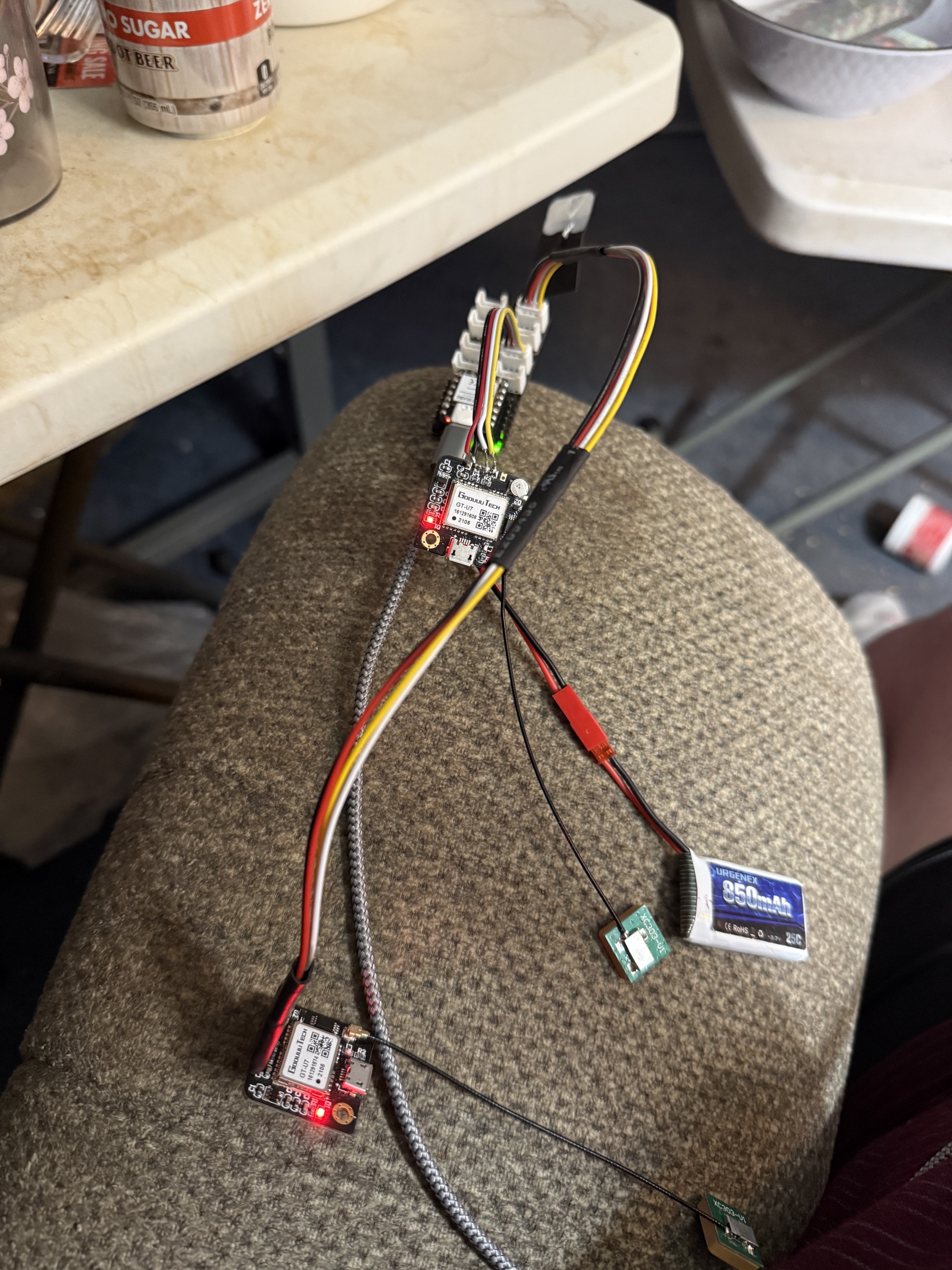
also GPS units are a good way to experiment with serial communications, i got my first lesson trying to listen to 2 GPS at the same time…
Your code basically works… slight changes, posted below…
#include <Arduino.h>

// #include <HardWareSerial.h>
// Define Hardware serial pins and baud rate
const int TEST_TX_PIN = D10;
const int TEST_RX_PIN = D9;

const uint32_t BAUD = 9600;

HardwareSerial USBSerial(1);

char RSout[32];

void setup()
{
  Serial.begin(9600);
  // while (!Serial); // Optional: wait for USB monitor to open

  delay(5000);

  Serial.println("*** Good Morning ***");
  Serial.println("*** Loopback Test Start (D10/D9) ***");

  // Map UART1 to new pins
  USBSerial.begin(BAUD, SERIAL_8N1, TEST_RX_PIN, TEST_TX_PIN);

  int len = USBSerial.availableForWrite();

  Serial.print("*** Test len = ");
  Serial.print(len);
  Serial.println(" ***");

  Serial.println("*** Ready to receive Serial Input ***");
}

void loop()
{
  if (Serial.available())
  {
    String usb_msg = Serial.readStringUntil('\n');

    usb_msg.trim();

    sprintf(RSout, usb_msg.c_str());

    Serial.print("Sending out via D9: |");
    Serial.print(RSout);
    Serial.println("| ...");

    USBSerial.println(RSout);
    USBSerial.flush();
  }

  if (USBSerial.available())
  {
    Serial.println("... Data received on D10 ...");
    String serial1_msg = USBSerial.readStringUntil('\n');

    Serial.print("--- SUCCESS via D10: ");
    Serial.println(serial1_msg); // Received back in on D4
  }
}
Response on Serial Terminal.
ESP-ROM:esp32c6-20220919
Build:Sep 19 2022
rst:0x3 ESP-ROM:esp32c6-20220919
Build:Sep 19 2022
rst:0x18 (JTAG_CPU),boot:0x6f (SPI_FAST_FLASH_BOOT)
Saved PC:0x2000084c
SPIWP:0xee
mode:DIO, clock div:2
load:0x40875720,len:0x1260
load:0x4086c110,len:0xdd0
load:0x4086e610,len:0x3030
entry 0x4086c110
*** Good Morning ***
*** Loopback Test Start (D10/D9) ***
*** Test len = 128 ***
*** Ready to receive Serial Input ***

Serial Test<CR><LF>

Sending out via D9: |Serial Test| ...
... Data received on D10 ...
--- SUCCESS via D10: Serial Test

Serial Test<CR><LF>

Sending out via D9: |Serial Test| ...
... Data received on D10 ...
--- SUCCESS via D10: Serial Test
Alright grobasoz,
Thank you for doing this, wow!!! I had struggled for hours, trying soft serial, hard serial, many sample codes found, and AI recommendations. Just changing the pin designations worked! So, while the solution is there, I am not sure why? I normally use DX numbers, but do not write code too often, and fell back to just numbers for the pin designation, which of course did not work.
From here I’ll move to serial between two cpu’s, then move to adding the RS485 modules. I have these MAX485 modules that supposedly handle 3.3V serial input and have auto handling between send and receive. We’ll see as they do not use the RS3485, but have external circuitry that supposedly converts 3.3V to the needed 5V.
thanks again,
Rob
The Arduino pins map to GPIO based on the selected device.
So D10 maps to GPIO 18 (excerpt from XIAO ESP32C6 pins_arduino.h).
static const uint8_t D0 = 0;
static const uint8_t D1 = 1;
static const uint8_t D2 = 2;
static const uint8_t D3 = 21;
static const uint8_t D4 = 22;
static const uint8_t D5 = 23;
static const uint8_t D6 = 16;
static const uint8_t D7 = 17;
static const uint8_t D8 = 19;
static const uint8_t D9 = 20;
static const uint8_t D10 = 18;
So, you could have used…
const int TEST_TX_PIN = 18; // D10
const int TEST_RX_PIN = 20; // D9

// or

const int TEST_TX_PIN = GPIO_NUM_18; // D10;
const int TEST_RX_PIN = GPIO_NUM_20; // D9;
… which is what I would have done (allowing me to use a “generic” ESP32C6 as well as a XIAO ESP32C6).