XIAO ESP32C3 Multiple Software Serial Ports

Ok so need a refresh on setting up multiple serial (Uart) ports on XIAO-ESP32C3

https://www.seeedstudio.com/Grove-Shield-for-Seeeduino-XIAO-p-4621.html?

Right now I am trying to set up 2 gps units
I am trying to set up one port as the D2 port and the D8 port
I am assuming this is software serial… as i have given up on trying to use the hardware serial… with the exception of the USB Serial Monitor

I may use the hardware UART D6/D7 for Nextion Display

It is currently throwing compile errors… too many to list so I am wondering if someone knows to start from scratch and build 2 softwareserialGPS connections on these ports… why do i need 2 gps connections… I dont I just have 2 gps devices in hand and the easiest way to get 2 devices communicating

I am using tinygps library

I want to make sure it runs on a XIAO ESP32C3

I tried to start with standard 2 port recieve sketch

Works on XIAO SAMD but not XIAO ESP32C3

In file included from C:\Arduino\TinyGPSPlus\KitchenSink\KitchenSink.ino:3:
c:\Arduino\libraries\espsoftwareserial\src/SoftwareSerial.h:282:26: error: 'Delegate' does not name a type
  282 |     void onReceive(const Delegate<void(), void*>& handler);
      |                          ^~~~~~~~
c:\Arduino\libraries\espsoftwareserial\src/SoftwareSerial.h:282:34: error: expected ',' or '...' before '<' token
  282 |     void onReceive(const Delegate<void(), void*>& handler);
      |                                  ^
c:\Arduino\libraries\espsoftwareserial\src/SoftwareSerial.h:289:20: error: 'Delegate' has not been declared
  289 |     void onReceive(Delegate<void(), void*>&& handler);
      |                    ^~~~~~~~
c:\Arduino\libraries\espsoftwareserial\src/SoftwareSerial.h:289:28: error: expected ',' or '...' before '<' token
  289 |     void onReceive(Delegate<void(), void*>&& handler);
      |                            ^
c:\Arduino\libraries\espsoftwareserial\src/SoftwareSerial.h:289:10: error: 'void EspSoftwareSerial::UARTBase::onReceive(int)' cannot be overloaded with 'void EspSoftwareSerial::UARTBase::onReceive(int)'
  289 |     void onReceive(Delegate<void(), void*>&& handler);
      |          ^~~~~~~~~
c:\Arduino\libraries\espsoftwareserial\src/SoftwareSerial.h:282:10: note: previous declaration 'void EspSoftwareSerial::UARTBase::onReceive(int)'
  282 |     void onReceive(const Delegate<void(), void*>& handler);
      |          ^~~~~~~~~
c:\Arduino\libraries\espsoftwareserial\src/SoftwareSerial.h:328:44: error: expected ';' at end of member declaration
  328 |     static inline uint32_t IRAM_ATTR ticks() ALWAYS_INLINE_ATTR {
      |                                            ^
      |                                             ;
c:\Arduino\libraries\espsoftwareserial\src/SoftwareSerial.h:328:46: error: 'ALWAYS_INLINE_ATTR' does not name a type; did you mean 'FORCE_INLINE_ATTR'?
  328 |     static inline uint32_t IRAM_ATTR ticks() ALWAYS_INLINE_ATTR {
      |                                              ^~~~~~~~~~~~~~~~~~
      |                                              FORCE_INLINE_ATTR
c:\Arduino\libraries\espsoftwareserial\src/SoftwareSerial.h:335:67: error: expected ';' at end of member declaration
  335 |     static inline uint32_t IRAM_ATTR microsToTicks(uint32_t micros) ALWAYS_INLINE_ATTR {
      |                                                                   ^
      |                                                                    ;
c:\Arduino\libraries\espsoftwareserial\src/SoftwareSerial.h:335:69: error: 'ALWAYS_INLINE_ATTR' does not name a type; did you mean 'FORCE_INLINE_ATTR'?
  335 |     static inline uint32_t IRAM_ATTR microsToTicks(uint32_t micros) ALWAYS_INLINE_ATTR {
      |                                                                     ^~~~~~~~~~~~~~~~~~
      |                                                                     FORCE_INLINE_ATTR
c:\Arduino\libraries\espsoftwareserial\src/SoftwareSerial.h:342:56: error: expected ';' at end of member declaration
  342 |     static inline uint32_t ticksToMicros(uint32_t ticks) ALWAYS_INLINE_ATTR {
      |                                                        ^
      |                                                         ;
c:\Arduino\libraries\espsoftwareserial\src/SoftwareSerial.h:342:58: error: 'ALWAYS_INLINE_ATTR' does not name a type; did you mean 'FORCE_INLINE_ATTR'?
  342 |     static inline uint32_t ticksToMicros(uint32_t ticks) ALWAYS_INLINE_ATTR {
      |                                                          ^~~~~~~~~~~~~~~~~~
      |                                                          FORCE_INLINE_ATTR
c:\Arduino\libraries\espsoftwareserial\src/SoftwareSerial.h:379:10: error: 'unique_ptr' in namespace 'std' does not name a template type
  379 |     std::unique_ptr<circular_queue<uint8_t> > m_buffer;
      |          ^~~~~~~~~~
c:\Arduino\libraries\espsoftwareserial\src/SoftwareSerial.h:25:1: note: 'std::unique_ptr' is defined in header '<memory>'; did you forget to '#include <memory>'?
   24 | #include <circular_queue.h>
  +++ |+#include <memory>
   25 | #include <Stream.h>
c:\Arduino\libraries\espsoftwareserial\src/SoftwareSerial.h:380:10: error: 'unique_ptr' in namespace 'std' does not name a template type
  380 |     std::unique_ptr<circular_queue<uint8_t> > m_parityBuffer;
      |          ^~~~~~~~~~
c:\Arduino\libraries\espsoftwareserial\src/SoftwareSerial.h:380:5: note: 'std::unique_ptr' is defined in header '<memory>'; did you forget to '#include <memory>'?
  380 |     std::unique_ptr<circular_queue<uint8_t> > m_parityBuffer;
      |     ^~~
c:\Arduino\libraries\espsoftwareserial\src/SoftwareSerial.h:390:10: error: 'unique_ptr' in namespace 'std' does not name a template type
  390 |     std::unique_ptr<circular_queue<uint32_t, UARTBase*> > m_isrBuffer;
      |          ^~~~~~~~~~
c:\Arduino\libraries\espsoftwareserial\src/SoftwareSerial.h:390:5: note: 'std::unique_ptr' is defined in header '<memory>'; did you forget to '#include <memory>'?
  390 |     std::unique_ptr<circular_queue<uint32_t, UARTBase*> > m_isrBuffer;
      |     ^~~
c:\Arduino\libraries\espsoftwareserial\src/SoftwareSerial.h:391:11: error: 'Delegate' does not name a type
  391 |     const Delegate<void(uint32_t&&), UARTBase*> m_isrBufferForEachDel { [](UARTBase* self, uint32_t&& isrTick) { self->rxBits(isrTick); }, this };
      |           ^~~~~~~~
c:\Arduino\libraries\espsoftwareserial\src/SoftwareSerial.h:392:10: error: 'atomic' in namespace 'std' does not name a template type
  392 |     std::atomic<bool> m_isrOverflow { false };
      |          ^~~~~~
c:\Arduino\libraries\espsoftwareserial\src/SoftwareSerial.h:25:1: note: 'std::atomic' is defined in header '<atomic>'; did you forget to '#include <atomic>'?
   24 | #include <circular_queue.h>
  +++ |+#include <atomic>
   25 | #include <Stream.h>
c:\Arduino\libraries\espsoftwareserial\src/SoftwareSerial.h:395:5: error: 'Delegate' does not name a type
  395 |     Delegate<void(), void*> m_rxHandler;
      |     ^~~~~~~~

exit status 1

Compilation error: exit status 1

ok I fixed that problem by removing and replacing the espsoftwareserial library

Hi there,

Given,
Most Important:
– The standard Arduino SoftwareSerial library isn’t officially supported on ESP32. Instead, you’ll need a library designed for ESP32 (for example, ESPSoftwareSerial or an alternative).
– Be sure to install and include the appropriate software serial library for your ESP32-C3.
– Also note that not all pins on the ESP32-C3 can be used for software serial RX/TX. Check the documentation for your board and library to ensure the pins are supported.
– You must specify all settings (baud rate, data bits, stop bits) if the library supports that. In this example, we set the baud rate to 9600 for both software serial ports.

Yea, and the Examples are further down the list UNDER ESPSoftwareSerial.
This one works ,

// Tested with Xiao ESP32C3 BSP ver. 3.0.7
// SoftSerial Version 8.1.0
// Support for High Baud rate is Sketchy, Bigger recieve buffers are limited by RAM constraints on C3
// Roasted and Toasted by PJG

#include <Arduino.h>
#include <SoftwareSerial.h> // Use an ESP32-compatible SoftwareSerial library

// Define baud rate for the software serial ports.
#define SOFTSERIAL_BAUD 9600

// Define pins for the first software serial port: TX on pin 6, RX on pin 7.
#define SS1_TX 6
#define SS1_RX 7

// Define pins for the second software serial port: TX on pin 8, RX on pin 9.
#define SS2_TX 8
#define SS2_RX 9

// Create two instances of ESPSoftwareSerial.
// The constructor parameters are (RX, TX)
SoftwareSerial softSerial1(SS1_RX, SS1_TX);
SoftwareSerial softSerial2(SS2_RX, SS2_TX);

void setup() {
  // Start hardware Serial (USB serial) at 115200 baud.
  Serial.begin(115200);
  delay (2000);
  //  ; // Wait for Serial connection
  //}
  Serial.println("Hardware Serial is ready.");

  // Start the software serial ports.
  softSerial1.begin(SOFTSERIAL_BAUD);
  softSerial2.begin(SOFTSERIAL_BAUD);
  Serial.println("Software Serial ports are ready.");

  // (Optional) If your library supports additional configuration for data bits,
  // stop bits, parity, etc., you can configure them here.
}

void loop() {
  // If data is available on the hardware serial, read it and forward it
  // to both software serial ports.
  if (Serial.available()) {
    String data = Serial.readStringUntil('\n');
    Serial.print("Received on hardware serial: ");
    Serial.println(data);
    softSerial1.println(data);
    softSerial2.println(data);
  }

  // If data is available on softSerial1, print it to hardware serial.
  if (softSerial1.available()) {
    String data = softSerial1.readStringUntil('\n');
    Serial.print("Received on softSerial1: ");
    Serial.println(data);
  }

  // If data is available on softSerial2, print it to hardware serial.
  if (softSerial2.available()) {
    String data = softSerial2.readStringUntil('\n');
    Serial.print("Received on softSerial2: ");
    Serial.println(data);
  }

  delay(10);
}

3 ports , note the baud rates.

HTH
GL :slight_smile: PJ :v:

BTW, The Library Info shows this as the example so stick close to that , you should be golden. :+1:

#include <SoftwareSerial.h>

#define MYPORT_TX 12
#define MYPORT_RX 13

EspSoftwareSerial::UART myPort;

[...]

Serial.begin(115200); // Standard hardware serial port

myPort.begin(38400, SWSERIAL_8N1, MYPORT_RX, MYPORT_TX, false);
if (!myPort) { // If the object did not initialize, then its configuration is invalid
  Serial.println("Invalid EspSoftwareSerial pin configuration, check config"); 
  while (1) { // Don't continue with invalid configuration
    delay (1000);
  }
} 

[...]

still doesnt seem to be working… SAMD with its code works… but no go on C3 or S3

Hi there,
paste up the code… :+1:
let me try.
GL :slight_smile: PJ :v:

ok standby… i have changed it so many times i am not sure which is the correct one

One of the problems to note… I dont think it is my problem, but it will cause problems…

The Grove Digital Ports are of the style

GND-3v3-(#+1)-(#)
(Black)(Red)(White)(Yellow)

But… two ports, D5/IIC and D7/UART is reversed
GND-3v3-(#-1)-(#)

Hi there,
Yellow is always the primary signal wire.
HTH
GL :slight_smile: PJ :v:

#include <TinyGPSPlus.h>
#include <SoftwareSerial.h>

//static const int gpsRXPin = 0, gpsTXPin = 1; //GPS on Port D0
//static const int gpsRXPin = 1, gpsTXPin = 2; //GPS on Port D1
//static const int gpsRXPin = 2, gpsTXPin = 3; //GPS on Port D2
//static const int gpsRXPin = 5, gpsTXPin = 4; //GPS on Port D5/IIC (Pins Reversed)
//static const int gpsRXPin = 7, gpsTXPin = 6; //GPS on Port D7/UART (Pins Reversed)
//static const int gpsRXPin = 8, gpsTXPin = 9; //GPS on Port D8
static const int gpsRXPin = 9, gpsTXPin = 10; //GPS on Port D9

static const uint32_t gpsBaud = 9600;
static const uint32_t smonBaud = 9600;

// The TinyGPSPlus object
TinyGPSPlus gps;

// The serial connection to the GPS device
SoftwareSerial gps_Serial(gpsRXPin, gpsTXPin);

void setup()
{
  Serial.begin(smonBaud);
    while (!Serial) 
  {//Begin while()
    Serial.println("\nSerial Setup..."); // wait for serial port to connect. 
  }//  End while()

  gps_Serial.begin(gpsBaud);

  Serial.println("FullExample.ino");
  Serial.println("An extensive example of many interesting TinyGPSPlus features");
  Serial.print("Testing TinyGPSPlus library v. "); 
  Serial.println(TinyGPSPlus::libraryVersion());
  Serial.println("by Mikal Hart");
  Serial.println();
  Serial.println("Sats HDOP  Latitude   Longitude   Fix  Date       Time     Date Alt    Course Speed Card  Distance Course Card  Chars Sentences Checksum");
  Serial.println("           (deg)      (deg)       Age                      Age  (m)    --- from GPS ----  ---- to London  ----  RX    RX        Fail");
  Serial.println("----------------------------------------------------------------------------------------------------------------------------------------");
}

void loop()
{
  static const double LONDON_LAT = 51.508131, LONDON_LON = -0.128002;

  printInt(gps.satellites.value(), gps.satellites.isValid(), 5);
  printFloat(gps.hdop.hdop(), gps.hdop.isValid(), 6, 1);
  printFloat(gps.location.lat(), gps.location.isValid(), 11, 6);
  printFloat(gps.location.lng(), gps.location.isValid(), 12, 6);
  printInt(gps.location.age(), gps.location.isValid(), 5);
  printDateTime(gps.date, gps.time);
  printFloat(gps.altitude.meters(), gps.altitude.isValid(), 7, 2);
  printFloat(gps.course.deg(), gps.course.isValid(), 7, 2);
  printFloat(gps.speed.kmph(), gps.speed.isValid(), 6, 2);
  printStr(gps.course.isValid() ? TinyGPSPlus::cardinal(gps.course.deg()) : "*** ", 6);

  unsigned long distanceKmToLondon =
    (unsigned long)TinyGPSPlus::distanceBetween(
      gps.location.lat(),
      gps.location.lng(),
      LONDON_LAT, 
      LONDON_LON) / 1000;
  printInt(distanceKmToLondon, gps.location.isValid(), 9);

  double courseToLondon =
    TinyGPSPlus::courseTo(
      gps.location.lat(),
      gps.location.lng(),
      LONDON_LAT, 
      LONDON_LON);

  printFloat(courseToLondon, gps.location.isValid(), 7, 2);

  const char *cardinalToLondon = TinyGPSPlus::cardinal(courseToLondon);

  printStr(gps.location.isValid() ? cardinalToLondon : "*** ", 6);

  printInt(gps.charsProcessed(), true, 6);
  printInt(gps.sentencesWithFix(), true, 10);
  printInt(gps.failedChecksum(), true, 9);
  Serial.println();
  
  smartDelay(1000);

  if (millis() > 5000 && gps.charsProcessed() < 10)
    Serial.println(F("No GPS data received: check wiring"));
}

// This custom version of delay() ensures that the gps object
// is being "fed".
static void smartDelay(unsigned long ms)
{
  unsigned long start = millis();
  do 
  {
    while (gps_Serial.available())
      gps.encode(gps_Serial.read());
  } while (millis() - start < ms);
}

static void printFloat(float val, bool valid, int len, int prec)
{
  if (!valid)
  {
    while (len-- > 1)
      Serial.print('*');
    Serial.print(' ');
  }
  else
  {
    Serial.print(val, prec);
    int vi = abs((int)val);
    int flen = prec + (val < 0.0 ? 2 : 1); // . and -
    flen += vi >= 1000 ? 4 : vi >= 100 ? 3 : vi >= 10 ? 2 : 1;
    for (int i=flen; i<len; ++i)
      Serial.print(' ');
  }
  smartDelay(0);
}

static void printInt(unsigned long val, bool valid, int len)
{
  char sz[32] = "*****************";
  if (valid)
    sprintf(sz, "%ld", val);
  sz[len] = 0;
  for (int i=strlen(sz); i<len; ++i)
    sz[i] = ' ';
  if (len > 0) 
    sz[len-1] = ' ';
  Serial.print(sz);
  smartDelay(0);
}

static void printDateTime(TinyGPSDate &d, TinyGPSTime &t)
{
  if (!d.isValid())
  {
    Serial.print(F("********** "));
  }
  else
  {
    char sz[32];
    sprintf(sz, "%02d/%02d/%02d ", d.month(), d.day(), d.year());
    Serial.print(sz);
  }
  
  if (!t.isValid())
  {
    Serial.print(F("******** "));
  }
  else
  {
    char sz[32];
    sprintf(sz, "%02d:%02d:%02d ", t.hour(), t.minute(), t.second());
    Serial.print(sz);
  }

  printInt(d.age(), d.isValid(), 5);
  smartDelay(0);
}

static void printStr(const char *str, int len)
{
  int slen = strlen(str);
  for (int i=0; i<len; ++i)
    Serial.print(i<slen ? str[i] : ' ');
  smartDelay(0);
}


FullExample.zip (1.7 KB)

This code is from
TinyGPSPlus-ESP32
and
ESPSoftwareSerial

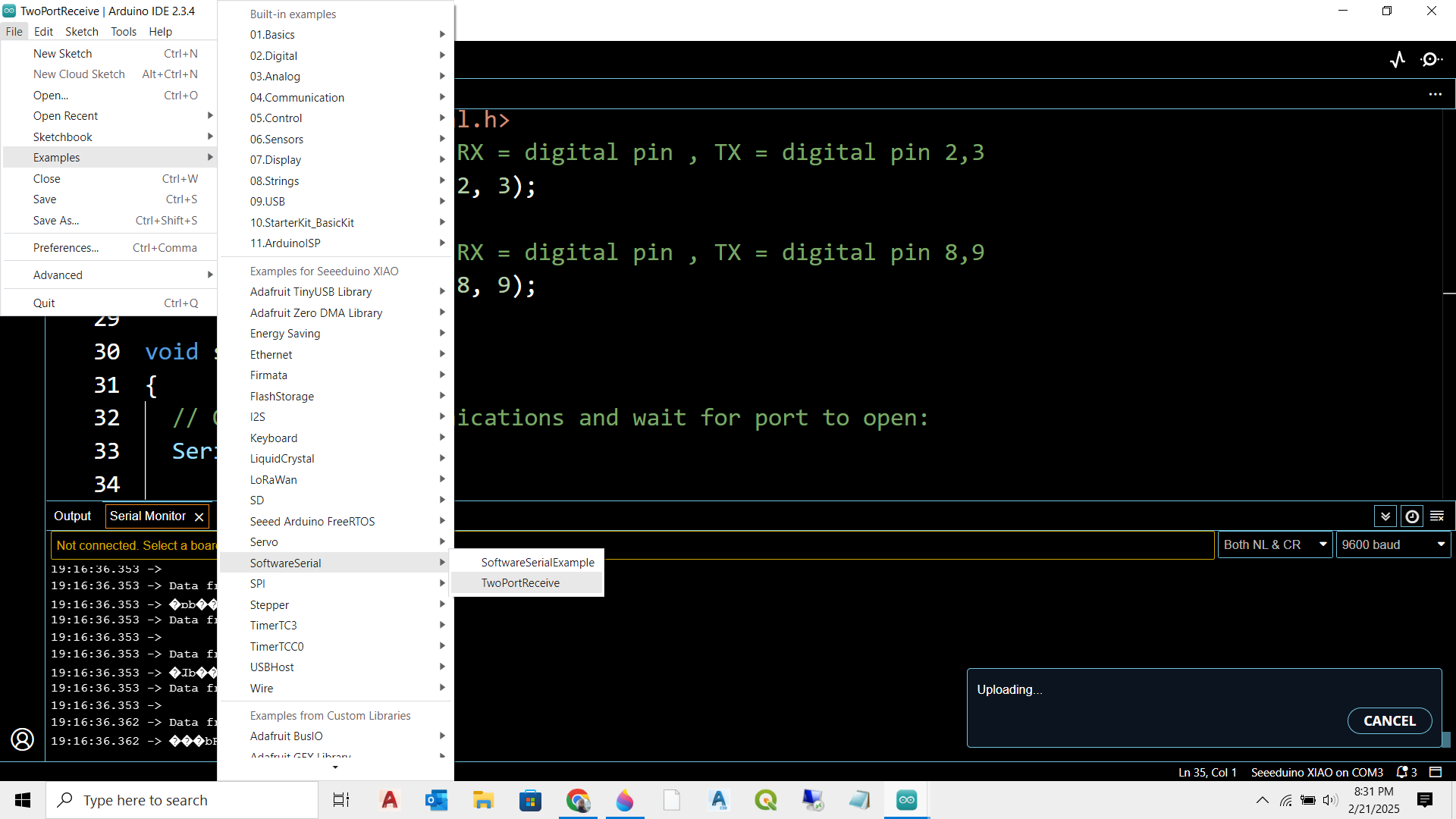
load from Arduino IDE

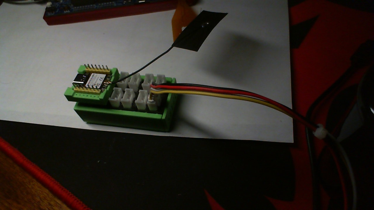
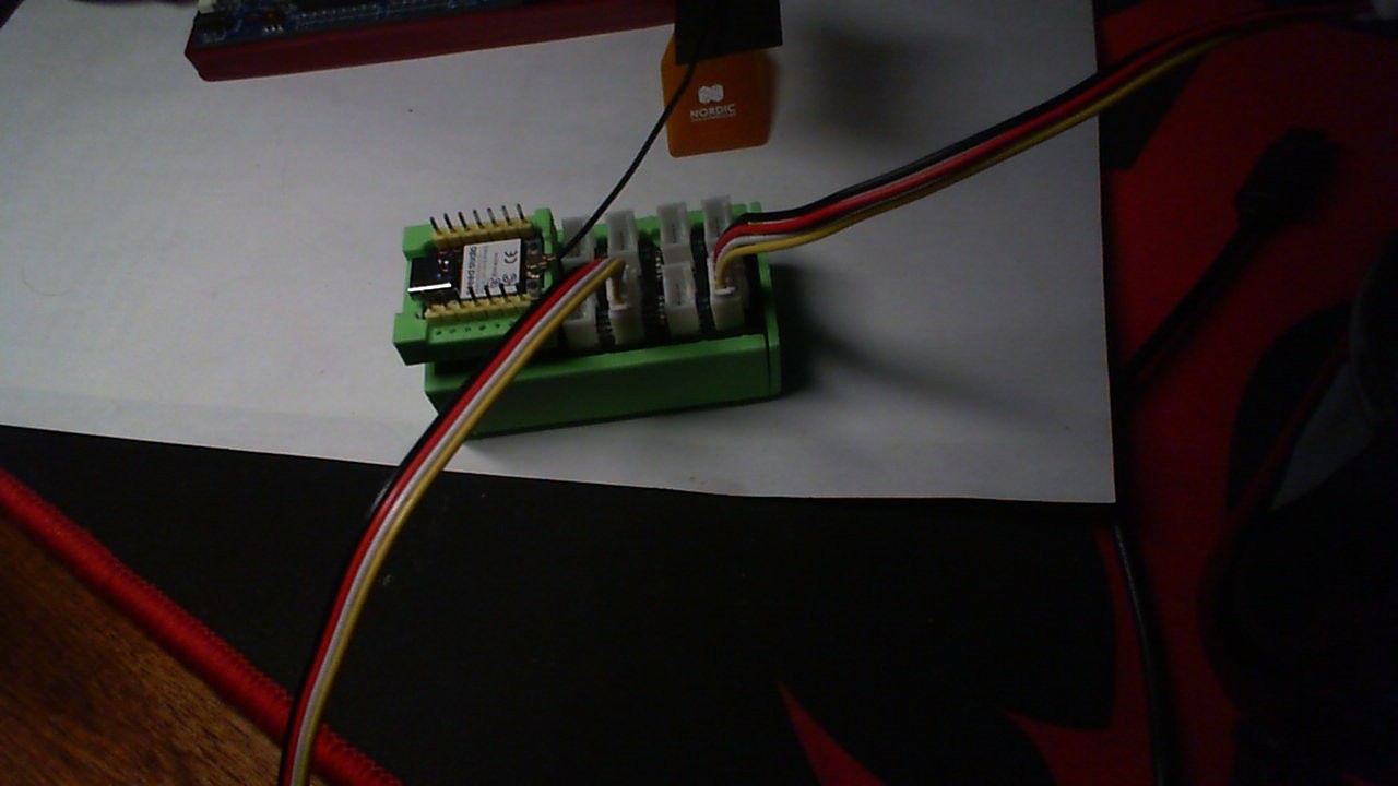
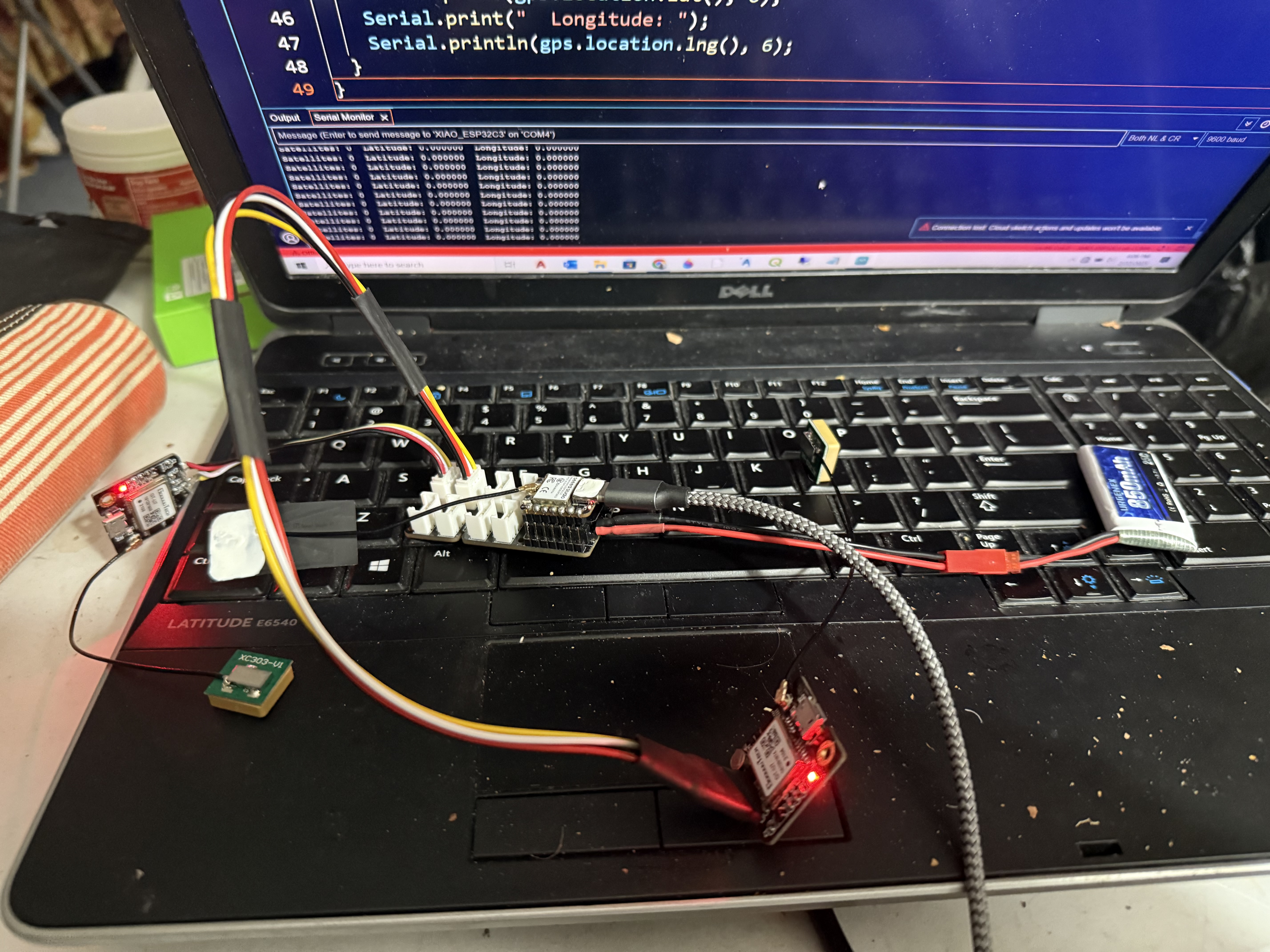
All ports run on XIAO Grove Expansion Board with XIAO SAMD
will not run with XIAO ESP32C3

Hi there,

Try this and I will post what I see…

#include <TinyGPSPlus.h>
#include <HardwareSerial.h>

// Create a TinyGPSPlus instance to parse the GPS data.
TinyGPSPlus gps;

// Use HardwareSerial for the GPS. On the ESP32-C3, UART0 is usually used for USB serial,
// so we can use UART1 for the GPS.
HardwareSerial SerialGPS(1);

// Define the pins for the GPS.
const int gpsRXPin = 9; // GPS TX goes to ESP32 RX (pin 9)
const int gpsTXPin = 10; // GPS RX goes to ESP32 TX (pin 10)

const uint32_t gpsBaud = 9600;

void setup() {
  // Start the primary hardware Serial (for USB debugging) at 115200 baud.
  Serial.begin(115200);
  while (!Serial) {
    ; // Wait for Serial connection.
  }
  Serial.println("Starting GPS example using HardwareSerial on ESP32-C3");
  
  // Begin HardwareSerial on UART1 for GPS.
  // The constructor for begin() is: begin(baud, config, rxPin, txPin)
  SerialGPS.begin(gpsBaud, SERIAL_8N1, gpsRXPin, gpsTXPin);
  Serial.println("GPS HardwareSerial initialized.");
}

void loop() {
  // Feed any available GPS data from SerialGPS to TinyGPSPlus.
  while (SerialGPS.available() > 0) {
    char c = SerialGPS.read();
    gps.encode(c);
  }

  // Print some parsed GPS data every second.
  static unsigned long lastPrint = 0;
  if (millis() - lastPrint > 1000) {
    lastPrint = millis();
    Serial.print("Satellites: ");
    Serial.print(gps.satellites.value());
    Serial.print("  Latitude: ");
    Serial.print(gps.location.lat(), 6);
    Serial.print("  Longitude: ");
    Serial.println(gps.location.lng(), 6);
  }
}

HTH
GL :slight_smile: PJ :v:

example that uses HardwareSerial instead of SoftwareSerial for the GPS on pins 9 (RX) and 10 (TX):

  • HardwareSerial Instance:
    We create a HardwareSerial instance named SerialGPS on UART1. On the ESP32-C3, you generally have at least two UARTs available (UART0 is used for USB serial, so UART1 is free for your peripheral).
  • Pin Assignment:
    We assign gpsRXPin (9) and gpsTXPin (10) for the GPS. Make sure your wiring matches this (i.e., the GPS module’s TX should connect to ESP32’s RX and vice versa).
  • Reading and Parsing Data:
    The loop reads available data from SerialGPS and feeds it into TinyGPSPlus for parsing.

Check the serial monitor for startup and data , LMK
:v:

Starting GPS example using HardwareSerial on ESP32-C3
GPS HardwareSerial initialized.
Satellites: 0  Latitude: 0.000000  Longitude: 0.000000

Hi there,

On ESP32 devices (including the ESP32-C3), the standard Arduino SoftwareSerial library isn’t well supported. The ESP32 (and ESP32-C3) has multiple hardware UARTs, which are far more reliable and efficient than SoftwareSerial. If you’re using SoftwareSerial on your Xiao ESP32-C3 for a GPS module on pins 9 & 10 (and another device on pins 6 & 7), you might run into timing and compatibility issues that prevent it from working correctly.

What You Can Do

  1. Use Hardware Serial Instead:
    The ESP32-C3 provides multiple hardware UARTs. Instead of relying on SoftwareSerial, you can use one of these hardware UARTs (for example, UART1) to handle your GPS data. This is both more reliable and easier to configure.
  2. Configure the Correct Pins:
    You can assign the desired RX/TX pins for the hardware UART in your code. For example, if you want to use pins 9 and 10 for the GPS, you can create a HardwareSerial instance (say, Serial1) that uses these pins.
  3. Multiple Serial Ports:
    If you have another device on pins 6 & 7, you can similarly assign it to another hardware UART (for example, UART2, if available) or use SoftwareSerial only if absolutely necessary (but hardware is preferred).

HTH
GL :slight_smile: PJ :v:

Here’s a quick summary based on the chips used in the Xiao series:

  • ESP32-C3:
    The ESP32-C3 chip provides 2 hardware UART controllers. One is usually used for USB serial (the console), and the other is available for your own application.
  • ESP32-S3:
    The ESP32-S3 chip also provides 2 hardware UART controllers. (Unlike the original ESP32, which had 3, the S3 – like the C3 – typically comes with 2.)
  • ESP32-C6:
    The ESP32-C6 is a newer chip and is designed with a richer peripheral set. According to its datasheet, it provides 3 hardware UART controllers.

Keep in mind that while the chip may support these numbers, the actual board (the Xiao variant) may only expose a subset of them on headers depending on the design. However, these are the numbers available on the chip itself.

I may have to dig a C6 out and solder some header pins…
This software serial thing is crap

Hi there,

Just not well supported I used BSP 3.0.7 BTW for the C3

so the general idea. On the ESP32-based Xiao boards (for example, the ESP32-C3 or ESP32-S3), one hardware UART is typically used for USB debugging/console (UART0), and the chip provides a second hardware UART that you can assign to available pins (like pins 6 and 7, if the board design allows). That gives you a reliable, hardware-based serial port for your application.

If you need an additional serial interface (for a third channel), you could try using a software serial library (like ESPSoftwareSerial or another ESP32‑compatible library) on a pair of other pins (such as pins 9 and 10). However, keep in mind:

  • Hardware UARTs are Always Preferred:
    The hardware UARTs on the ESP32 are much more reliable and efficient than software serial. Software serial on ESP32 can be a bit tricky due to timing issues, so if you can avoid it by reassigning or using a hardware UART (or if you’re using an ESP32-C6 with three UARTs), that’s usually best.
  • Pin Multiplexing and Board Design:
    Not all pins on the board may support the functions required for a software serial receiver, so you’ll need to verify that pins 9 and 10 (or whichever you choose) are supported by the library you plan to use.
  • Configuration:
    For each serial port (whether hardware or software), you need to define the correct pins, baud rate, data bits, stop bits, and parity if necessary.

So, in summary:

  • Use the USB port (UART0) as usual.
  • Use the second hardware UART on the available pins (like 6 & 7) for one channel.
  • If needed, add another channel via SoftwareSerial (e.g. on pins 9 & 10), keeping in mind potential limitations.

That way, you can have three serial channels: one hardware (USB), one hardware on assigned pins, and one software serial.

HTH
GL :slight_smile: PJ :v:

The example I posted uses Hardware Serial , but assigns the pins to 9 & 10 so the cable plugs straight in the last Grove connector.
:+1:

1 Like

im going to try that… the problem is i need more than 2 and 1 for serial monitor… maybe for final project i could do away with USB

You should end up with this and 3 devices…
USB for monitor, GPS on Hardwares Serial (pins 9&10),
Software serial (pins 6 & 7) We know those are compatible SS pins BTW…

I think the all 000s is not working

If you use my code it will report no gps check wireing