Xiao ESP32-C6 and Waveshare 2.9" e-Paper b/w, 296x128 Pixel, Rev2.1

Hi all,

Could sure use some advice and help. I’m not an expert here so bare with me.

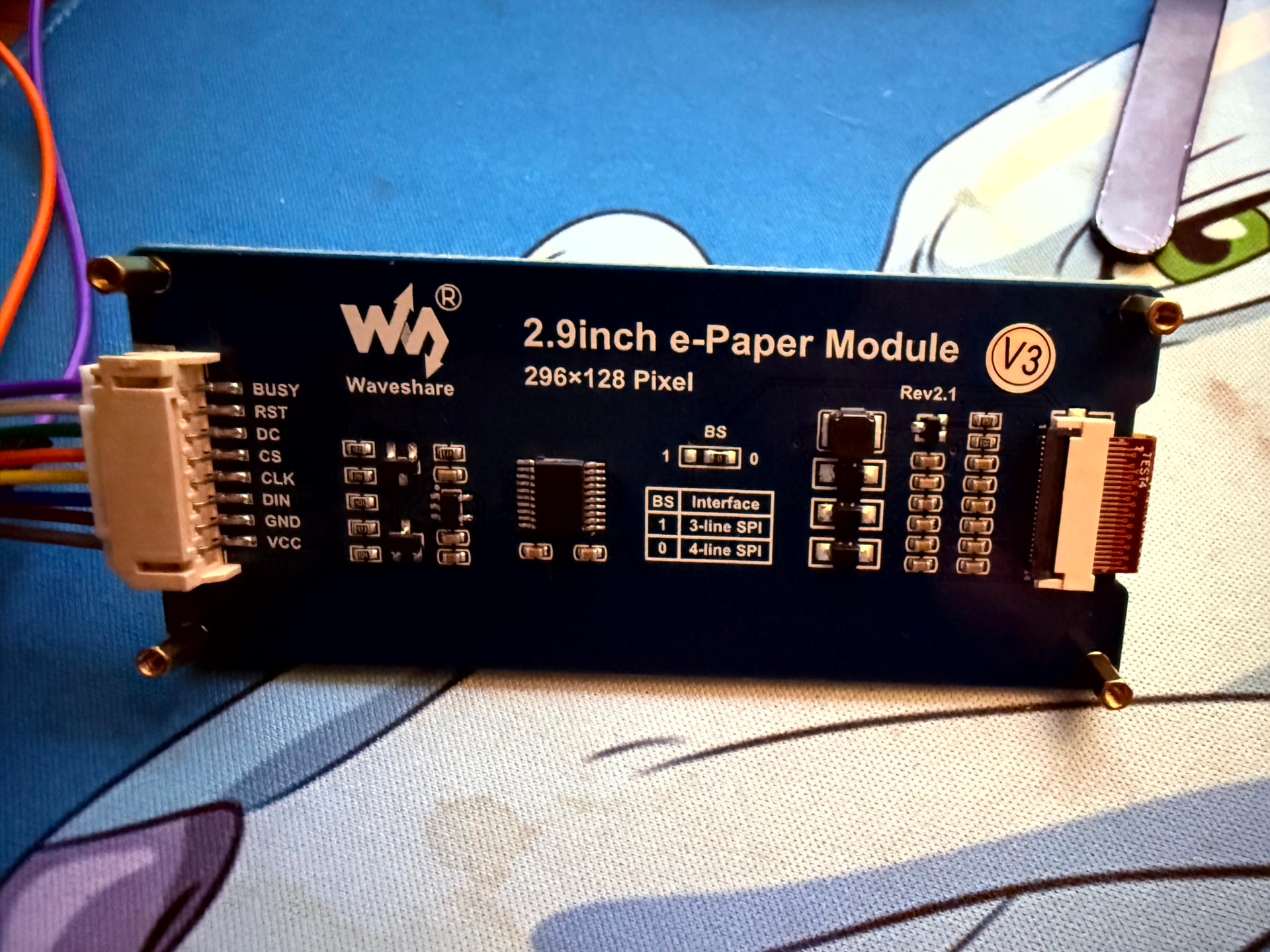
I have a Waveshare 2.9inch e-Paper b/w, 296x128 Pixel, Rev2.1. It has a “V3” shiny round sticker on it on the back. It has 8 wires from top to bottom:

BUSY
RST
DC
CS
CLK
DIN
GND
VCC

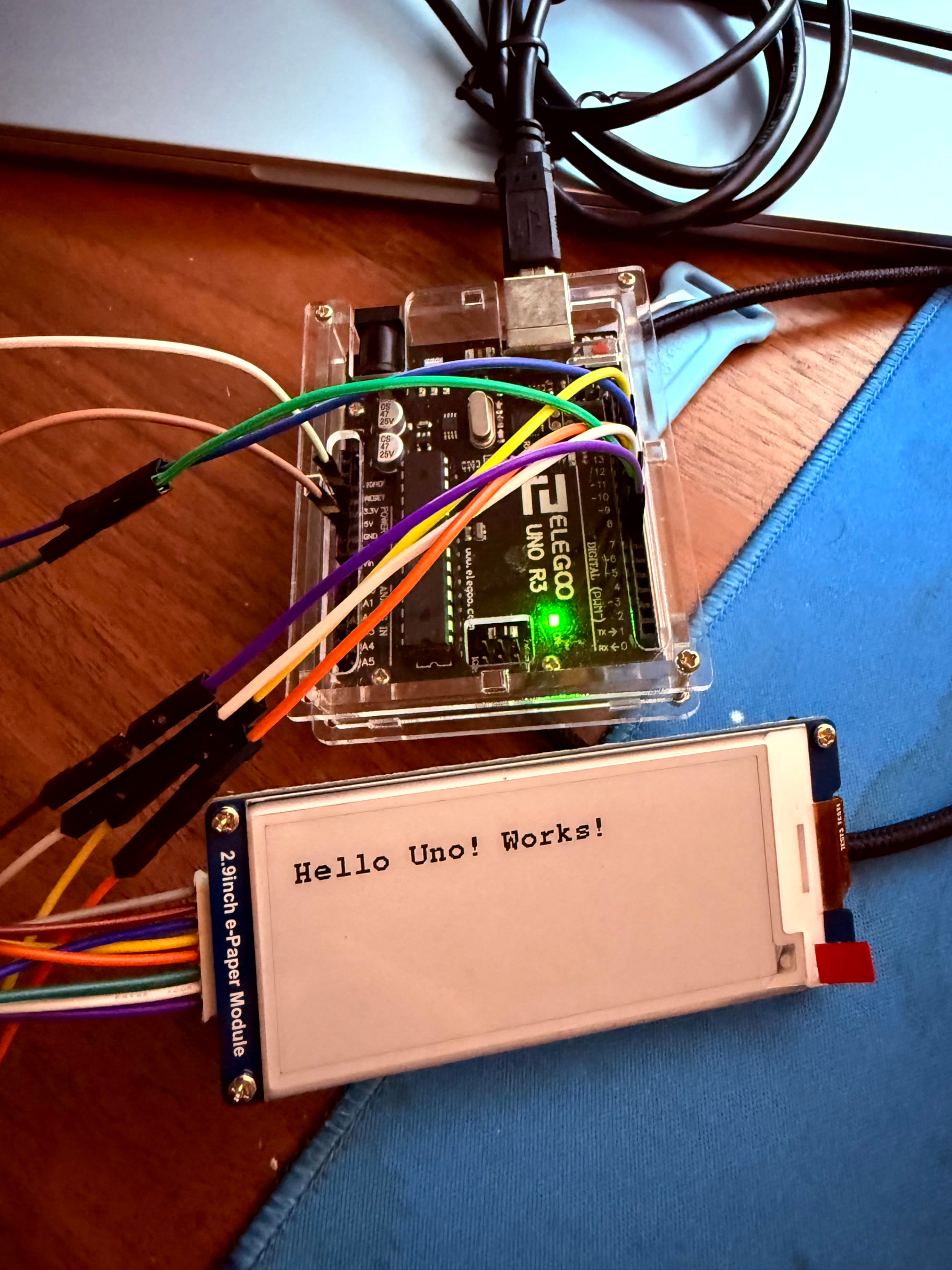
I managed to get it working via Arduino IDE using an Elegoo Uno R3, which has limited RAM (2048 bytes) so I had to use HEIGHT/16 to compensate. The setup was:

PINS:

Waveshare Pin Uno R3 Pin
VCC 3.3V
GND GND
DIN D11 (MOSI)
CLK D13 (SCK)
CS D10
DC D8
RST D9
BUSY D7

The code used is:

#include <GxEPD2_BW.h>
#include <Fonts/FreeMonoBold9pt7b.h>

// use only 1 page buffer
GxEPD2_BW<GxEPD2_290_T94, GxEPD2_290_T94::HEIGHT / 16>
display(GxEPD2_290_T94(10, 8, 9, 7));

void setup()
{
Serial.begin(115200);

display.init(115200);

display.setRotation(1);
display.setFont(&FreeMonoBold9pt7b);
display.setTextColor(GxEPD_BLACK);

display.firstPage();
do
{
display.fillScreen(GxEPD_WHITE);
display.setCursor(10, 30);
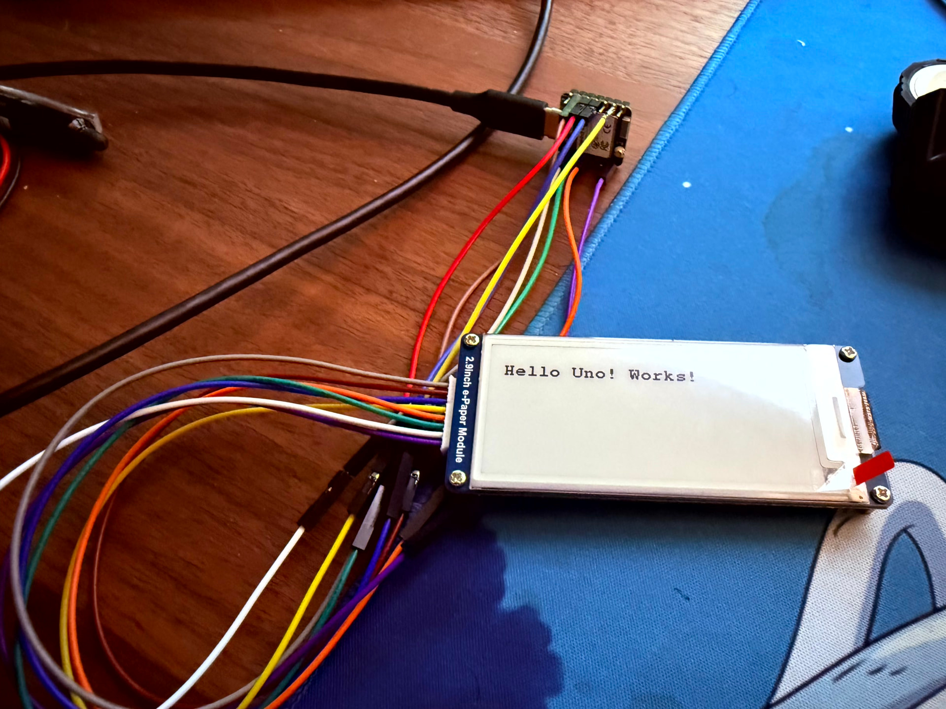
display.println(“Hello Uno! Works!”);
}
while (display.nextPage());
display.hibernate();   // power down display driver
}

void loop()
{
}

Now the challenge is, I also have a Xiao ESP32-C6 microcontroller. I’ve tried all sorts of pin combinations and code but it just refuses to work ! It did manage to work once using the below,

Purple (BUSY) → D2
White (RST) → D0
Green (DC) → D3
Orange (CS) → D1
Yellow (CLK) → D8
Blue (DIN) → D10
Brown (GND) → GND
Grey (VCC) → 3V3

I think the code used was this:

#include “driver.h”
#include “TFT_eSPI.h”

#ifdef EPAPER_ENABLE
EPaper epaper;
#endif

void setup() {
Serial.begin(115200);
delay(1000);
Serial.println(“=== BOOT ===”);

#ifdef EPAPER_ENABLE
Serial.println(“Calling begin…”);
epaper.begin();
Serial.println(“begin done”);

epaper.setRotation(1);
epaper.fillScreen(TFT_WHITE);
epaper.setTextSize(2);
epaper.setTextColor(TFT_BLACK);
epaper.setCursor(10, 40);
epaper.print("Hello Retirement!");

Serial.println("Calling update...");
epaper.update();
Serial.println("update done");

#endif
}

void loop() {}

but when trying again it just wouldn’t work any more.. I tried both

USE_XIAO_EPAPER_BREAKOUT_BOARD
and
USE_XIAO_EPAPER_DRIVER_BOARD,

can’t remember which one worked, but neither do any more.

I also tested unplugging from USB and removing the 3V3 pin for 30s (hard reset).. No change.

I’m at a loss if it is compatible or not..

As per Schematics I tried several different pin layouts. For example

Wire Colour Signal XIAO Pin
Grey VCC 3V3
Brown GND GND
Blue DIN D10
Yellow CLK D8
Orange CS D3
Green DC D2
White RST D1
Purple BUSY D6

I have also tried using BUSY into D6 instead of D1. No change.

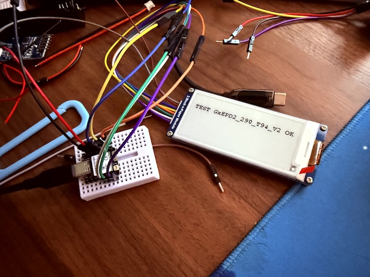
I tried different drivers like TxEPD2_290, no difference, The only thing I see in serial monitor is:

Starting…
_PowerOn : 60001
_Update_Full : 2
_Update_Part : 2
_Update_Full : 2
_PowerOff : 2
_PowerOff : 2
Done.

But the screen doesn’t update. BUSY signal does start at 1 then changes to 0 in a loop, so I’m confident it does work.. And like I said this does work on the Arduino Uno R3.

Please help! What am I doing wrong? :frowning: Does it not work with the ESP32-C6?

Thanks.

Hi there,

And Welcome here…

SO , do you have a picture to post?

I have used the 4" version, I recall it was a PITA but turned out to be loading the Driver After the TFT_eSPI.LIB that blew me up for a day.
I’ll dig up those notes, but there is a thread on here with the 4" check that out forsure.
Time permitting I will try your code and see what shakes out, Standby one.

HTH
GL :slight_smile: PJ :v:

It will work, just a process in getting it too.
:grin:

Morning :slight_smile:

Sure thing, let me know if there are any other pics you need. I have these 3. First with Elgoo Uno R3 which does work, though I had to click the RST button on it to trigger the refresh.

Second is with the ESP32-C6, which didn’t update the screen - It should show something like “Hello Retirement”. Third is the back side of the display.

I honestly can’t remember what code is supposed to be the right one on the ESP any more, I tried so many different ones, troubleshooting/debug ones, etc. But my aim is to (hopefully!) use the GxEPD2 on the ESP32-C6 as it seems to be more ‘modern’. Though at this rate I’ll settle with whatever that works.

Forgot to note, my driver.h is:

#define BOARD_SCREEN_COMBO 504 // 2.9 inch monochrome ePaper Screen (SSD1680)
//#define USE_XIAO_EPAPER_DRIVER_BOARD
#define USE_XIAO_EPAPER_BREAKOUT_BOARD

I also just tested with

#include <GxEPD2_BW.h>
#include <Fonts/FreeMonoBold9pt7b.h>
#include <SPI.h>

// --- Pin definitions (XIAO ESP32-C6) ---
#define EPD_CS   D3   // Orange
#define EPD_DC   D2   // Green
#define EPD_RST  D1   // White
#define EPD_BUSY D6   // Purple

#define EPD_SCK  D8   // Yellow
#define EPD_MOSI D10  // Blue

// Create a dedicated SPI instance
SPIClass epdSPI(FSPI);

// Display driver (your panel worked with this on UNO)
GxEPD2_BW<GxEPD2_290_T94, GxEPD2_290_T94::HEIGHT> display(
  GxEPD2_290_T94(EPD_CS, EPD_DC, EPD_RST, EPD_BUSY)
);

void setup()
{
  Serial.begin(115200);
  delay(1500);

  Serial.println("Starting EPaper test...");

  // Hard reset pulse (helps with stuck panels)
  pinMode(EPD_RST, OUTPUT);
  digitalWrite(EPD_RST, LOW);
  delay(200);
  digitalWrite(EPD_RST, HIGH);
  delay(200);

  // Force SPI pins explicitly
  epdSPI.begin(EPD_SCK, -1, EPD_MOSI, EPD_CS);

  // Use slower SPI speed for reliability
  display.epd2.selectSPI(epdSPI, SPISettings(1000000, MSBFIRST, SPI_MODE0));

  display.init(115200);

  display.setRotation(1);
  display.setFont(&FreeMonoBold9pt7b);
  display.setTextColor(GxEPD_BLACK);

  display.firstPage();
  do
  {
    display.fillScreen(GxEPD_WHITE);
    display.setCursor(10, 30);
    display.println("XIAO ESP32-C6");
    display.setCursor(10, 55);
    display.println("GxEPD2 TEST OK");
  }
  while (display.nextPage());

  display.hibernate();
  Serial.println("Done.");
}

void loop()
{
}

And changed the driver to GxEPD2_BW<GxEPD2_290, GxEPD2_290::HEIGHT> still no luck :frowning:

Thanks for the help!


Hi there,

Ok , that looks about right. I ran it through the LLM and I added the 4" post info.
So, This specific log means the ESP32-C6 is running through the code and executing the SPI commands successfully as far as the software is concerned, but the display panel itself isn’t reacting. Here are the three most likely reasons this 2.9" layout is failing while the 4" setup works:

1. The Wrong Display Driver Class (The SSD1680 vs. IL0373 Trap)

Waveshare’s 2.9" Rev2.1 panel with the “V3” sticker uses the SSD1680 driver chip. In his code, he tried:

  • GxEPD2_290_T94 (which maps to the GDEM029T94 / IL0373 chip)
  • GxEPD2_290 (which maps to older IL3820 chips)

Because he is calling the wrong chip class, the initialization phases, voltage booster frequencies, and look-up tables (LUT) being sent over SPI do not match what the SSD1680 controller expects. The SPI bus functions cleanly (which is why the code doesn’t freeze), but the display cannot generate the physical charges required to flip the e-ink microcapsules. :backhand_index_pointing_left: :saluting_face:

  • The Fix: He needs to change his display instantiation to target the SSD1680 explicitly. In GxEPD2, this is usually defined as:C++GxEPD2_BW<GxEPD2_290_GDEH029A1, GxEPD2_290_GDEH029A1::HEIGHT> display(GxEPD2_290_GDEH029A1(EPD_CS, EPD_DC, EPD_RST, EPD_BUSY));

2. ESP32-C6 SPI Pin Mapping Restrictions

The ESP32-C6 allows you to remap SPI to almost any pins via the GPIO matrix, but D8 (GPIO19) and D10 (GPIO22) can sometimes conflict with default hardware internal paths depending on the board package or core definition being used.

  • He explicitly mapped FSPI manually in his code: epdSPI.begin(EPD_SCK, -1, EPD_MOSI, EPD_CS);
  • While your 4" layout might natively map cleanly, his manual overriding of FSPI pins while missing an MISO definition (-1) can occasionally cause the ESP32-C6 Arduino core to misconfigure the peripheral clock timing. It’s often safer to rely on the global default SPI instance after calling SPI.begin(D8, -1, D10, D3) right at the start of setup().

3. Missing 5V to 3.3V Level Shifter Issues on the Uno vs. XIAO

The Uno runs on 5V logic, while the XIAO ESP32-C6 runs on 3.3V logic.

  • Many Waveshare e-Paper raw hats feature an onboard voltage level shifter (like the TXS0108) to handle 5V inputs from microcontrollers like the Arduino Uno.
  • When shifting down to a 3.3V controller like the XIAO, some revisions of the Waveshare hat require explicit, stable 3.3V logic inputs that match their internal VCC rails. If his specific 2.9" hat variant struggles with low-current logic lines from the low-power ESP32-C6 pins, the high-frequency SPI signals degrade, preventing the panel from cycling. Utilizing a slower SPI clock speed (like the 1000000 (1MHz) he added in his second test) is a good step, but fixing the driver class (Point 1) is the prerequisite.

Try the FIX first,

HTH
GL :slight_smile: PJ :v:

Thanks @PJ_Glasso ,

I won’t lie, I tried the above just now, and also tried the other ~100 tips and tests LLMs (claude & chatgpt) gave me.. nothing worked :frowning:

Drivers tried with GxEPD2, all result in _Update_Full : 6 (6 microseconds, instant):

  • GxEPD2_290_BS
  • GxEPD2_290_T94
  • GxEPD2_290_T94_V2
  • GxEPD2_290_GDEY029T94

That last one was what I could find that was the closest driver to your LLM’s recommendation.

➜ head -10 ~/Documents/git-projects/libraries/GxEPD2/src/gdey/GxEPD2_290_GDEY029T94.h
// Display Library for SPI e-paper panels from Dalian Good Display and boards from Waveshare.
// Requires HW SPI and Adafruit_GFX. Caution: the e-paper panels require 3.3V supply AND data lines!
//
// based on Demo Example from Good Display, available here: https://www.good-display.com/product/389.html
// Panel: GDEY029T94 : https://www.good-display.com/product/389.html
// Controller : SSD1680 : https://v4.cecdn.yun300.cn/100001_1909185148/SSD1680.pdf
//
// Author: Jean-Marc Zingg
//
// Version: see library.properties

Tested with:

#include <SPI.h>
#include <GxEPD2_BW.h>
#include <Fonts/FreeMonoBold9pt7b.h>

// Current wiring
static const uint8_t EPD_BUSY = 16;  // D6
static const uint8_t EPD_RST  = 1;   // D1
static const uint8_t EPD_DC   = 2;   // D2
static const uint8_t EPD_CS   = 21;  // D3
static const uint8_t EPD_SCK  = 19;  // D8
static const uint8_t EPD_MISO = -1;
static const uint8_t EPD_MOSI = 18;  // D10

GxEPD2_BW<GxEPD2_290_GDEY029T94, GxEPD2_290_GDEY029T94::HEIGHT> display(
    GxEPD2_290_GDEY029T94(EPD_CS, EPD_DC, EPD_RST, EPD_BUSY)
);

void setup() {
    Serial.begin(115200);
    delay(1000);
    Serial.println("=== BOOT ===");

    SPI.begin(EPD_SCK, EPD_MISO, EPD_MOSI, EPD_CS);
    display.init(115200, true, 2, false);
    SPI.end();
    SPI.begin(EPD_SCK, EPD_MISO, EPD_MOSI, EPD_CS);

    Serial.println("Init done");

    display.setRotation(1);
    display.setFullWindow();
    display.firstPage();
    do {
        display.fillScreen(GxEPD_WHITE);
        display.setFont(&FreeMonoBold9pt7b);
        display.setTextColor(GxEPD_BLACK);
        display.setCursor(10, 40);
        display.println("Hello Retirement!");
    } while (display.nextPage());
    display.hibernate();
    Serial.println("Done.");
}

void loop() {}

=== BOOT ===
Init done
_Update_Full : 6
_Update_Full : 2
Done.

Display doesn’t refresh at all.. I also tried moving BUSY to D4 and D0. Same..

Pins currently in use:

  • BUSY → D6 (GPIO16)
  • RST → D1 (GPIO1) — LP_GPIO, requires ESP-IDF gpio_config workaround
  • DC → D2 (GPIO2) — LP_GPIO, same workaround
  • CS → D3 (GPIO21)
  • CLK → D8 (GPIO19)
  • DIN → D10 (GPIO18)

Also tried: Waveshare’s own EPD_2in9_V2_test example with corrected pin assignments… no display update.

Throwing this question out there..

Given BUSY goes LOW immediately after commands (not HIGH as GxEPD2 expects), is there a way to add a delay between sending the update command (0x20) and checking BUSY, without modifying the library source? Or is the SSD1680 on this specific Waveshare V3 panel known to have different BUSY timing than what GxEPD2 expects?

Reason I ask that is because during raw SPI testing (bypassing GxEPD2 entirely), I sent commands directly to the display and monitored BUSY in real time:

BUSY before reset: 1 (HIGH = idle, correct)
BUSY after hardware reset: goes LOW immediately
BUSY after software reset (0x12): stays LOW
BUSY immediately after master activation (0x20): reads 0 (LOW)
BUSY 5ms after 0x20: reads 0 (LOW)
BUSY 50ms after 0x20: reads 0 (LOW)

The display never asserts BUSY HIGH after the activation command (0x20), meaning from GxEPD2’s perspective it looks like the display is always done. However in a separate test where the connector was reseated firmly, BUSY did go HIGH after activation and stayed HIGH for an extended period.. but the screen still didn’t visually update.

This to me suggests either:

A) The display needs a longer settling time between sending 0x20 and BUSY asserting HIGH , and GxEPD2’s delay(1) before checking isn’t enough

B) Or the init sequence being sent doesn’t match what this specific V3 panel’s SSD1680 variant expects, so the panel never triggers a refresh cycle at all

C) Or I’m so lost that I’ve dug myself into a rabbit hole..

I believe the Uno R3 worked because it uses a simpler, slower execution path and the timing accidentally works out. Either that or because the GxEPD2_290_T94 driver’s init sequence happens to be compatible.

I’m also going to email Waveshare support and ask for advice there too. They did get back to me saying that this display should be compatible with the C6, but there’s hardly any info in the wiki about it..

Hi there,

Well, it’s not like your not earning your stats forsure, :grin:

Good on you for sticking with it, You have looked at this thread i hope,

If not , check it and see in relations to the LLM’s recommends, see if there is an order or close config that may work. Your close.

I know it’s a Nrf part in that thread, but the INIT, I think you’re onto something there, so look into that, it may be you need to manually assert the DC or set it low initially, I seem to remember it was the last thing I tried and it worked , and I always started from a power on reset. FYI :+1:

HTH
GL :slight_smile: PJ :v:

I’ll keep looking and If time permits I can try a c6 with the 4.2" and see if any joy exists :crossed_fingers: re-reading the thread I remember :saluting_face:it was a task tio sort it out.
But I like you DO NOT give up that easy…LOL :face_savoring_food:

Thanks @PJ_Glasso ,

I must admit I do feel defeated..

Thanks for the link.. yea still no luck :cry: I can’t use your .bin because of the different controller, but I think the below should be similar to yours.

Testing with U8g2_for_Adafruit_GFX this time,

#include <GxEPD2_BW.h>
#include <U8g2_for_Adafruit_GFX.h>
#include <SPI.h>

// Pins for XIAO ESP32-C6
#define EPD_CS   D3
#define EPD_DC   D2
#define EPD_RST  D1
#define EPD_BUSY D6

#define EPD_SCK  D8
#define EPD_MOSI D10

// Use default SPI
GxEPD2_BW<GxEPD2_290, GxEPD2_290::HEIGHT> display(
  GxEPD2_290(EPD_CS, EPD_DC, EPD_RST, EPD_BUSY)
);

U8G2_FOR_ADAFRUIT_GFX u8g2Fonts;

void setup()
{
  Serial.begin(115200);
  delay(2000);

  Serial.println("GxEPD2 + U8G2 test");

  SPI.begin(EPD_SCK, -1, EPD_MOSI, EPD_CS);
  display.epd2.selectSPI(SPI, SPISettings(500000, MSBFIRST, SPI_MODE0));

  display.init(115200);

  u8g2Fonts.begin(display);  // connect u8g2 to display

  display.setRotation(1);

  display.firstPage();
  do
  {
    display.fillScreen(GxEPD_WHITE);

    u8g2Fonts.setFont(u8g2_font_helvB14_tf);
    u8g2Fonts.setForegroundColor(GxEPD_BLACK);
    u8g2Fonts.setCursor(0, 20);
    u8g2Fonts.print("HELLO");

    u8g2Fonts.setFont(u8g2_font_helvR10_tf);
    u8g2Fonts.setCursor(0, 50);
    u8g2Fonts.print("XIAO ESP32-C6");

    u8g2Fonts.setCursor(0, 70);
    u8g2Fonts.print("Waveshare 2.9");

  }
  while (display.nextPage());

  display.hibernate();
  Serial.println("Done.");
}

void loop() {}

Still no luck..

GxEPD2 + U8G2 test
_PowerOn : 20001
_Update_Full : 3000
_Update_Part : 5000
_Update_Full : 1
_PowerOff : 1
_PowerOff : 1
Done.

tried 500000 in SPISettings

GxEPD2 + U8G2 test
_PowerOn : 93001
_Update_Full : 2
_Update_Part : 2
_Update_Full : 2
_PowerOff : 2
_PowerOff : 2
Done.

I then tried the below brute force approach with the drivers.. again none worked.. I’m starting to wonder if my wiring is wrong or not.. but based on the schematics it should work.

#include <GxEPD2_BW.h>
#include <Fonts/FreeMonoBold9pt7b.h>
#include <SPI.h>

#define EPD_CS   D3
#define EPD_DC   D2
#define EPD_RST  D1
#define EPD_BUSY D6

#define EPD_SCK  D8
#define EPD_MOSI D10

SPIClass &spi = SPI;

// -------------------
// ROTATING BELOW ONE BY ONE
// -------------------
#define DRIVER GxEPD2_290_T94
//#define DRIVER GxEPD2_290_T94_V2
//#define DRIVER GxEPD2_290_BS
//#define DRIVER GxEPD2_290_M06
//#define DRIVER GxEPD2_290_T5
//#define DRIVER GxEPD2_290_T5D
//#define DRIVER GxEPD2_290_I6FD
//#define DRIVER GxEPD2_290

GxEPD2_BW<DRIVER, DRIVER::HEIGHT> display(DRIVER(EPD_CS, EPD_DC, EPD_RST, EPD_BUSY));

void setup()
{
  Serial.begin(115200);
  delay(2000);

  Serial.println("Driver test starting...");

  SPI.begin(EPD_SCK, -1, EPD_MOSI, EPD_CS);

  display.epd2.selectSPI(SPI, SPISettings(1000000, MSBFIRST, SPI_MODE0));

  display.init(115200, true, 20, false);

  display.setRotation(1);
  display.setFont(&FreeMonoBold9pt7b);
  display.setTextColor(GxEPD_BLACK);

  display.firstPage();
  do
  {
    display.fillScreen(GxEPD_WHITE);
    display.setCursor(0, 30);
    display.print("DRIVER:");
    display.setCursor(0, 60);
    display.print(__STRINGIFY(DRIVER));
  }
  while (display.nextPage());

  display.hibernate();

  Serial.println("Done.");
}

void loop() {}

At this point it looks like SPI + code path is running, but the panel is not completing a valid update cycle.

And yes, I also tried BUSY on D0.

I know the panel works though (it does on the Uno R3), but i’m losing hope here as it’s been 2 weeks now.. I’m wondering if i should cut my losses and try and find another panel that does work, like maybe the ones mentioned in the wiki

Hi there,

Ok, Humor me, and try this driver

// Waveshare 2.9" V2/Rev2.1 uses the GDEH029A1 template mapping for the SSD1680 chip
#define DRIVER GxEPD2_290_GDEH029A1

then in your setup(), call the global SPI bus normally:

SPI.begin(D8, -1, D10, D3); // SCK, MISO (-1), MOSI, CS

BTW, the C6 does NOT like anything below, ESP32-C6 core’s hardware SPI driver matrix frequently hates trying to calculate integer clock dividers below 2 MHz on its master peripheral clock bus.

Change the library transaction speed back up to a standard working frequency for the C6 architecture:

display.epd2.selectSPI(SPI, SPISettings(4000000, MSBFIRST, SPI_MODE0)); // Use 4MHz

On the Seeed Studio XIAO ESP32-C6 layout, D6 maps to a pin that can occasionally experience hardware state-changes during network initialization or background execution loop cycles.

If he moves BUSY to D0, updates his pin definitions to #define EPD_BUSY D0, changes the driver define to #define DRIVER GxEPD2_290_GDEH029A1, and uses standard 4MHz SPI settings, the panel should cleanly execute its refresh loops!

Give it a go. and report back, you’re so close it’s the SD1608 vs. SSD1680
LLM, agrees.
Why this fails: In the GxEPD2 library context, GxEPD2_290 points directly to the legacy IL3820 or SSD1608 controller chips. However, the Waveshare 2.9" V2 / Rev2.1 panel with the “V3” sticker is built around the modern SSD1680 driver chip.

Because he is passing the wrong driver layout to the library, the display registers are misaligning, and the internal charge pumps are never turning on to move the physical ink.

  • The Exact Class Fix: He needs to change his definition to use the actual SSD1680 target built into the library. Tell him to replace his driver class block entirely with this explicit mapping:
  • // Waveshare 2.9" V2/Rev2.1 uses the GDEH029A1 template mapping for the SSD1680 chip #define DRIVER GxEPD2_290_GDEH029A1

It has got to work, IMO.

HTH
GL :slight_smile: PJ :v:

SPI.begin(EPD_SCK, -1, EPD_MOSI, EPD_CS);
display.epd2.selectSPI(SPI, SPISettings(500000, MSBFIRST, SPI_MODE0));

Why this fails on the XIAO ESP32-C6: Setting the SPI speed down to 500000 (500 kHz) or 1000000 (1 MHz) is usually a smart way to debug long cables.

YOLO

:smiling_face_with_sunglasses:

I had to switch to GxEPD2_290_GDEY029T94 (since GDEH029A1 is not present in my installed GxEPD2 v1.6.9). I hope that’s ok.. Couldn’t figure out how to find it.

Compilation error: ‘GxEPD2_290_GDEH029A1’ was not declared in this scope; did you mean ‘GxEPD2_290_GDEY029T94’?

I just tested with the above and BUSY on D0, but it gives me a timeout:

#include <GxEPD2_BW.h>
#include <Fonts/FreeMonoBold9pt7b.h>
#include <SPI.h>

#define EPD_CS   D3
#define EPD_DC   D2
#define EPD_RST  D1
#define EPD_BUSY D0

#define EPD_SCK  D8
#define EPD_MOSI D10

SPIClass &spi = SPI;

#define DRIVER GxEPD2_290_GDEY029T94

GxEPD2_BW<DRIVER, DRIVER::HEIGHT> display(DRIVER(EPD_CS, EPD_DC, EPD_RST, EPD_BUSY));

void setup()
{
  Serial.begin(115200);
  delay(2000);

  Serial.println("Driver test starting...");

  SPI.begin(D8, -1, D10, D3); // SCK, MISO (-1), MOSI, CS

  display.epd2.selectSPI(SPI, SPISettings(500000, MSBFIRST, SPI_MODE0)); // Use 4MHz

  display.init(115200, true, 20, false);

  display.setRotation(1);
  display.setFont(&FreeMonoBold9pt7b);
  display.setTextColor(GxEPD_BLACK);

  display.firstPage();
  do
  {
    display.fillScreen(GxEPD_WHITE);
    display.setCursor(0, 30);
    display.print("DRIVER:");
    display.setCursor(0, 60);
    display.print(__STRINGIFY(DRIVER));
  }
  while (display.nextPage());

  display.hibernate();

  Serial.println("Done.");
}

void loop() {}
Driver test starting...
Busy Timeout!
_Update_Full : 10001027

And yep, tested 4mhz, 1mhz, 500hz too.

I have confirmed that it works with the Waveshare 1.54-inch display and the ESP32C6. Please try using Adafruit_ThinkInk.h. My connections are as follows:

#include “Adafruit_ThinkInk.h”  // Adafruit EPD 4.6.2

#define EPD_DC D5
#define EPD_CS D7
#define EPD_BUSY D3   // can be set to -1 to not use a pin (will wait a fixed delay)
#define SRAM_CS -1
#define EPD_RESET D4  // can be set to -1 and shared with the microcontroller’s Reset!
#define EPD_SPI &SPI  // primary SPI

// 1.54" Monochrome displays with 200x200 pixels and SSD1681 chipset
ThinkInk_154_Mono_D67 display(EPD_DC, EPD_RESET, EPD_CS, SRAM_CS, EPD_BUSY, EPD_SPI);


  display.begin(THINKINK_MONO);
1 Like

Thanks @msfujino ,

Bit of good news finally.

I just tested and same issue, did not refresh :frowning: The code I tested is as such but it again didn’t work for me :frowning:

#include <SPI.h>
#include <Adafruit_GFX.h>
#include <Adafruit_EPD.h>
#include "Adafruit_ThinkInk.h"

// ----- Pin mapping (XIAO ESP32-C6 stable SPI) -----
#define EPD_DC    D5
#define EPD_CS    D7
#define EPD_BUSY  D3
#define EPD_RESET D4
#define SRAM_CS   -1

// SPI pins
#define EPD_SCK   D8
#define EPD_MOSI  D10

// Create SPI instance
SPIClass epdSPI(FSPI);

// 1.54" SSD1681 panel (ONLY if your panel matches!)
ThinkInk_154_Mono_D67 display(EPD_DC, EPD_RESET, EPD_CS, SRAM_CS, EPD_BUSY, &epdSPI);

void setup() {
  Serial.begin(115200);
  delay(2000);

  Serial.println("ThinkInk test start");

  // SPI init (VERY important on ESP32-C6)
  epdSPI.begin(EPD_SCK, -1, EPD_MOSI, EPD_CS);

  display.begin(THINKINK_MONO);

  display.clearBuffer();
  display.setTextSize(2);
  display.setCursor(10, 40);
  display.print("HELLO");
  display.display();

  Serial.println("Done");
}

void loop() {
  delay(5000);
}

However, based on some more searches, I rearranged the wiring and tested below:

Signal XIAO pin
SCK D8
MOSI D10
CS D7
DC D5
RST D4
BUSY D3
GND GND
VCC 3V3
#include <GxEPD2_BW.h>
#include <SPI.h>

#define EPD_CS   D7
#define EPD_DC   D5
#define EPD_RST  D4
#define EPD_BUSY D3

#define EPD_SCK  D8
#define EPD_MOSI D10

#include <GxEPD2_3C.h>   // only if needed later (NOT now)

// IMPORTANT: BW driver only for sanity test
#define DRIVER GxEPD2_290_GDEY029T94

GxEPD2_BW<DRIVER, DRIVER::HEIGHT> display(DRIVER(EPD_CS, EPD_DC, EPD_RST, EPD_BUSY));

void setup() {
  Serial.begin(115200);
  delay(2000);

  SPI.begin(EPD_SCK, -1, EPD_MOSI, EPD_CS);

  display.epd2.selectSPI(SPI, SPISettings(2000000, MSBFIRST, SPI_MODE0));

  display.init(115200);

  display.setFullWindow();
  display.firstPage();
  do {
    display.fillScreen(GxEPD_WHITE);
    display.setCursor(10, 30);
    display.print("TEST OK");
  } while (display.nextPage());

  display.hibernate();
}

void loop() {}

And the screen actually refreshed! However, it’s a white screen now with a fuzzy black horizontal bar up top, which to me means it’s in a partially initialised state.

Either wrong driver timing, or BUSY handling issues (something i seem to be suffering from a lot).

Edit 2:

OK!!!

Changed EPD_BUSY to -1 and finally have a clear refreshed display!!

I’m going to test some more and update here soon. =D Man I just got a jolt of confidence and hope back. haha.

1 Like

Ok now putting BUSY back to D6 fixed the issue (got me out of using software timed refresh as a workaround).

So the issue was a combination of wrong pin layout (current one still looks strange to me but if it works it works..),and BUSY unset or on unstable GPIOs. Plus wrong drivers, which I’ll start testing with now that I have a working setup. I also replaced the cables and pushed the controller into the breadboard, since when I tested with my OLED, it was temperamental.

Thanks @msfujino , @PJ_Glasso ! I’ll take a break now and continue testing later on, will update teh thread in case anyone else has the same issue and needs a fix without reading through all the bad tests above.

1 Like

Yep all drivers work now. Final pin and code:

Signal XIAO pin
SCK D8
MOSI D10
CS D7
DC D5
RST D4
BUSY D6
GND GND
VCC 3V3
#include <GxEPD2_BW.h>
#include <Fonts/FreeMonoBold9pt7b.h>
#include <SPI.h>

// ---------------- PIN MAP ----------------
#define EPD_CS   D7
#define EPD_DC   D5
#define EPD_RST  D4
#define EPD_BUSY D6   // -1 if any issues, to disable

#define EPD_SCK  D8
#define EPD_MOSI D10

// ---------------- DRIVER ----------------
// Try this ONE first
#include <GxEPD2_3C.h>

//works, as backup:
// #define DRIVER_CLASS GxEPD2_290_GDEY029T94
// also works
// #define DRIVER_CLASS GxEPD2_290_T94

#define DRIVER_CLASS GxEPD2_290_T94_V2

GxEPD2_BW<DRIVER_CLASS, DRIVER_CLASS::HEIGHT>
display(DRIVER_CLASS(EPD_CS, EPD_DC, EPD_RST, EPD_BUSY));

void setup()
{
  Serial.begin(115200);
  delay(2000);

  Serial.println("EPD START");

  SPI.begin(EPD_SCK, -1, EPD_MOSI, EPD_CS);
  
  // can test with 4000000 if any issues
  display.epd2.selectSPI(SPI, SPISettings(4000000, MSBFIRST, SPI_MODE0));

  display.init(115200, true, 10, false); // was 50

  display.setRotation(1);
  display.setFont(&FreeMonoBold9pt7b);
  display.setTextColor(GxEPD_BLACK);

  display.firstPage();
  do
  {
    display.fillScreen(GxEPD_WHITE);
    display.setCursor(10, 40);
    display.print("TEST GxEPD2_290_T94_V2 OK");
  }
  while (display.nextPage());

  display.hibernate();

  Serial.println("DONE");
}

void loop() {}

Again thanks for all your help! I’m so happy! FYI This (if it keeps working) will end up as a display countdown to my retirement. lol.

Hi there,

WAY TO GO!..
:grin:

Awesome sticking with it, and the BIGGEST props for @msfujino to provide the solution
He has some Higher than AI x-ray vision on some of this stuff :smiley:

Looks Good TOO… :+1:

GL :slight_smile: PJ :v:

This is how stuff gets done.!

@PJ_Glasso , @msfujino ,

So I didn’t want to leave this as such with a “why the hell did it not work the way it should” lol.. I followed up via github and opened a bug report.

It looks like we were on to something. I can see a fix being implemented.

fix(esp32c6): use ESP-IDF gpio_config for LP_GPIO in XIAO ESP32C6 variant

fix(esp32c6): use ESP-IDF gpio_config for LP_GPIO in XIAO ESP32C6 variant
The upstream variant.cpp uses Arduino pinMode()/digitalWrite() on
GPIO3 (WIFI_ENABLE) which is a Low Power GPIO (LP_GPIO, GPIO 0~7).
The Arduino ESP32 periman abstraction has issues with LP_GPIO that
can silently corrupt the peripheral manager state, causing subsequent
GPIO operations on any pin to fail.

This breaks e-paper displays and other SPI peripherals that rely on
reliable GPIO control (see issue Seeed-Studio#46).

Changes:

  • Add variants/XIAO_ESP32C6/variant.cpp using ESP-IDF gpio_config()
    and gpio_set_level() to bypass the Arduino periman layer for LP_GPIO
  • Add variant override mechanism in esp_arduino.py that copies
    platform-local variant files over framework files before build

Closes: Seeed-Studio#46

If I understood correctly, it looks like GPIO0-7 (LP_GPIO) on the ESP32-C6 corrupt the Arduino peripheral manager when used with pinMode()/digitalWrite(), which then causes all subsequent GPIO operations to fail silently (including SPI).

Our current wiring from msfujino deliberately avoids LP_GPIO (0-7) for the display. D4 - D7 map to GPIO22/23/16/17 which are all safe high-numbered GPIOs. That’s why it works.

Just thought I’d share this in case it helps. It’ll help me in freeing up a pin i need for the RTC & ADC so I’ll test this out next week.

2 Likes