Xiao ESP32-C6 & ADS1292R: SPI issue

Hello everyone,

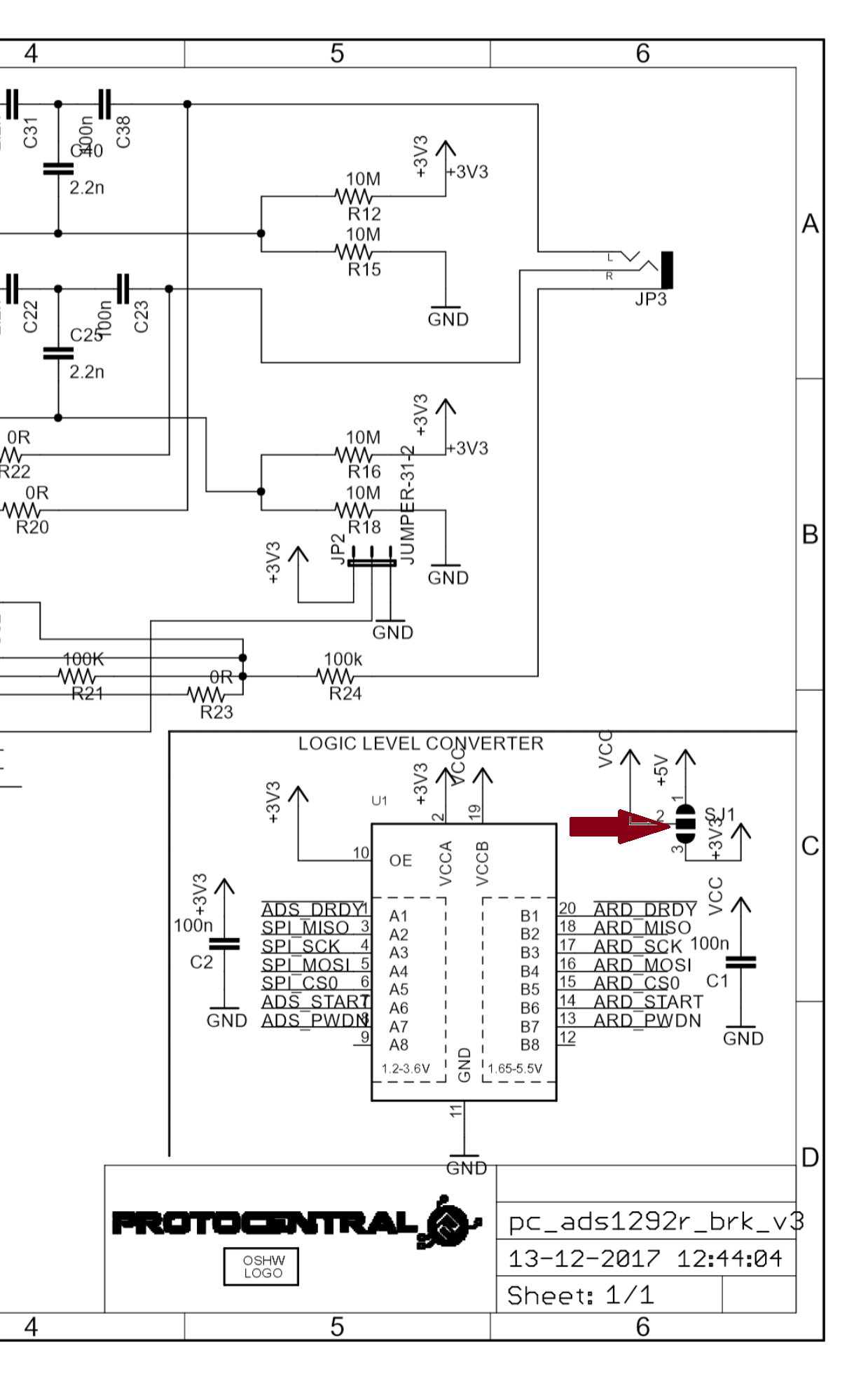
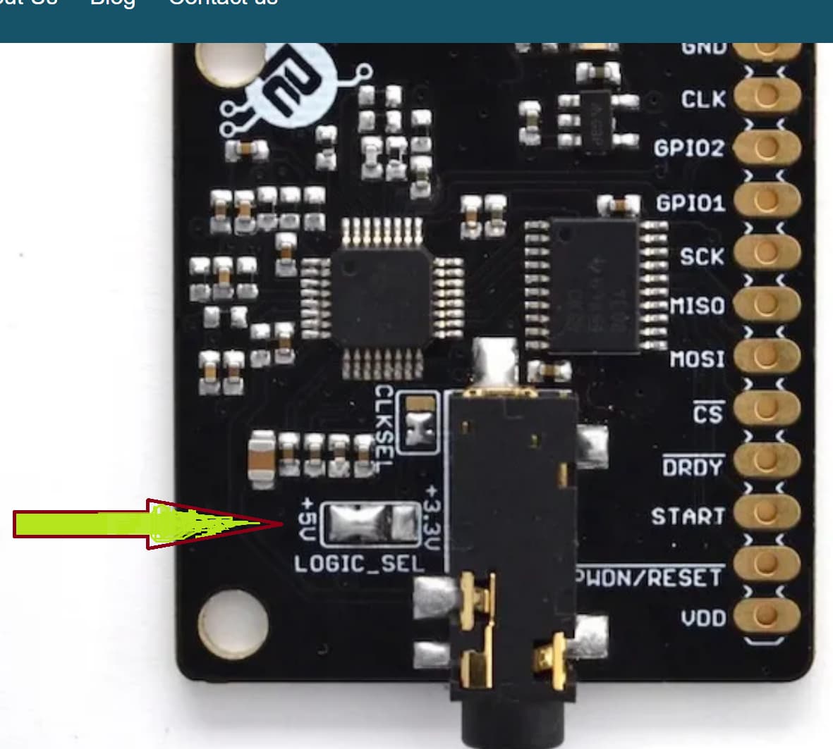
I recently discovered my interest in electronics and, as a first project, I am trying to build a small ECG system. To get myself acquainted with the basics and in order to make sure I get the software side running properly, I wanted to connect a breakout board (ProtoCentral ADS1292R ECG/Respiration Breakout Kit - Protocentral Electronics). I set it up with an Arduino Nano first and it works well when running just code to read the ID from the register of the ADS1292R (I took some code from the protocentral repo to initialize the ADS1292R).

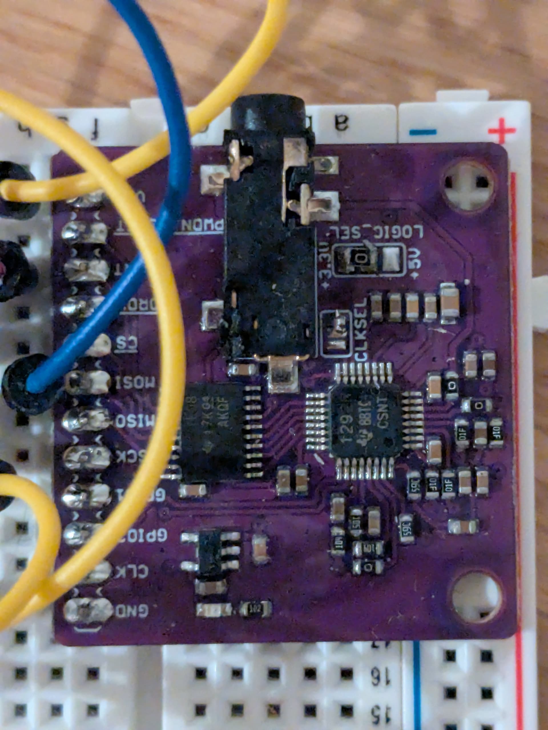
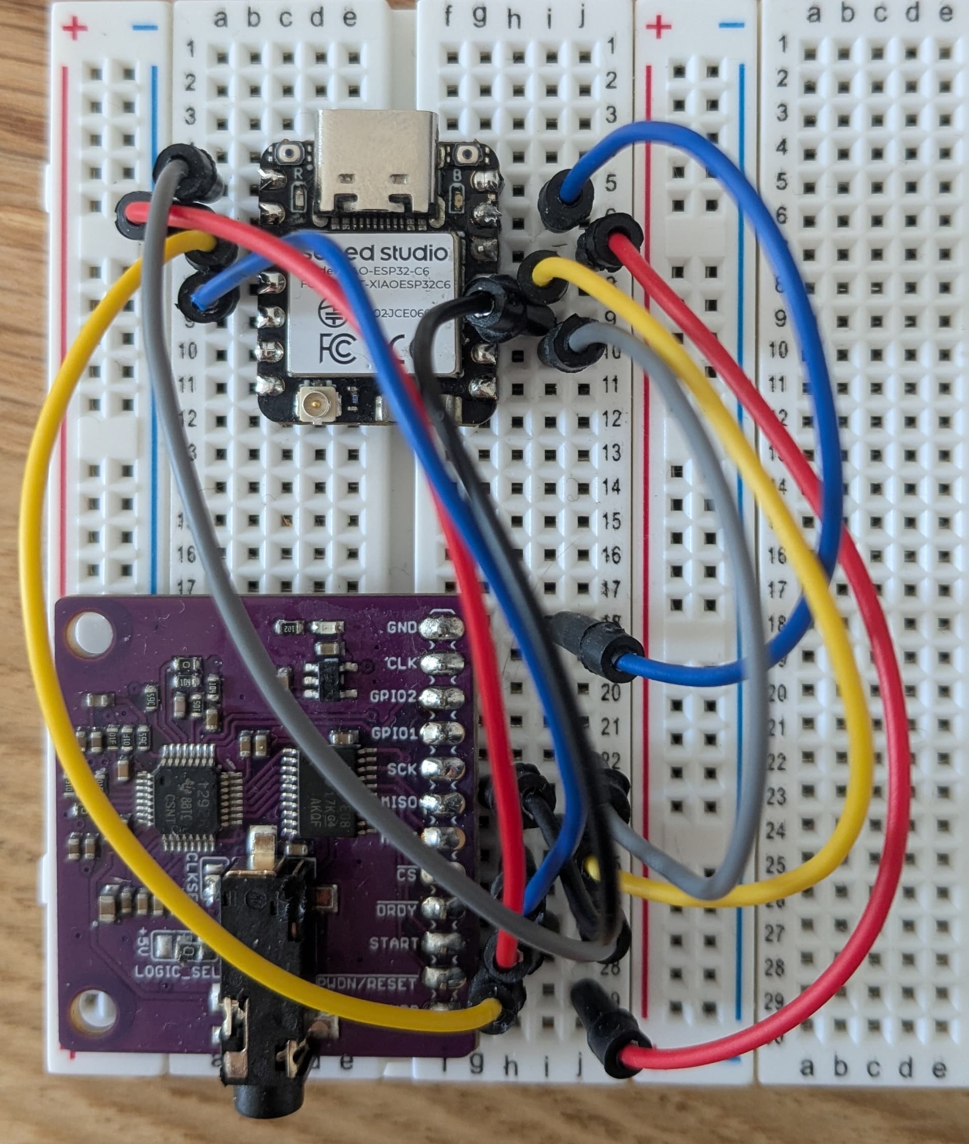
I am now trying to get it to run with a XIAO ESP32-C6, but I simply cannot establish the SPI communication. I took the code that ran on the Arduino and adjusted the SPI pins, but it doesn’t work. See below the code I’m trying to run right now. If anyone could help out or nudge me in the right direction, I’d be very grateful! Thanks a lot!

#include "protocentralAds1292r.h"
#include <SPI.h>

// Xiao ESP32-C6 config
const int ADS1292_DRDY_PIN = 0;
const int ADS1292_CS_PIN = 21;
const int ADS1292_START_PIN = 2;
const int ADS1292_PWDN_PIN = 17;
const int SPI_MISO = 20;
const int SPI_MOSI = 18;
const int SPI_SCK = 19;

ads1292r ADS1292R;

void sendSpiCommand(uint8_t cmd, uint8_t cs_pin) {
    digitalWrite(cs_pin, LOW);
    delayMicroseconds(10); 
    SPI.beginTransaction(SPISettings(100000, MSBFIRST, SPI_MODE1));
    SPI.transfer(cmd);
    SPI.endTransaction();
    digitalWrite(cs_pin, HIGH);
    delayMicroseconds(50); 
}

uint8_t readRegister(uint8_t reg, uint8_t cs_pin) {
  uint8_t value = 0;
  digitalWrite(cs_pin, LOW);
  delayMicroseconds(100); 
  SPI.beginTransaction(SPISettings(100000, MSBFIRST, SPI_MODE1));
  SPI.transfer(0x20 | (reg & 0x1F));  
  SPI.transfer(0x00);                
  value = SPI.transfer(0x00);         
  SPI.endTransaction();
  digitalWrite(cs_pin, HIGH);
  delayMicroseconds(200); 
  return value;
}

void setup()
{
  delay(2000);
  SPI.begin(SPI_SCK, SPI_MISO, SPI_MOSI, ADS1292_CS_PIN);

  // SPI.setBitOrder(MSBFIRST);
  // SPI.setDataMode(SPI_MODE1);
  // SPI.setClockDivider(SPI_CLOCK_DIV16);

  pinMode(ADS1292_DRDY_PIN, INPUT);
  pinMode(ADS1292_CS_PIN, OUTPUT);
  pinMode(ADS1292_START_PIN, OUTPUT);
  pinMode(ADS1292_PWDN_PIN, OUTPUT);
  Serial.begin(57600);

  digitalWrite(ADS1292_CS_PIN, HIGH); 
  delay(50);

  ADS1292R.ads1292Init(ADS1292_CS_PIN, ADS1292_PWDN_PIN, ADS1292_START_PIN);
  delay(500);

  sendSpiCommand(0x11, ADS1292_CS_PIN); 
  delay(10000);

  Serial.println("Reading register...");
  uint8_t id = readRegister(0x00, ADS1292_CS_PIN);
  Serial.println(id, HEX);
}

void loop()
{
}

Hi there,

So That sounds like a great project, The Xiao version is a little different than the Dev board so, those pins (numbers) won’t transfer.
Try this one and note the differences, Consult the Xiao Esp32C6 WiKi for the pin out. Your close but This should run for you. it compiles with BSP 3.1.3 the latest Board Support Package and Arduino 2.3.4 IDE

// REV 1.0 - ADS1292R SPI Communication Test on XIAO ESP32C6
// Board: Seeed Studio XIAO ESP32C6 + ADS1292R ECG Sensor Module

#include <SPI.h>
#include "protocentralAds1292r.h"

// ADS1292R Pin Assignments (adapted for XIAO ESP32C6)
const int ADS1292_DRDY_PIN  = D0;   // Data Ready
const int ADS1292_CS_PIN    = D3;   // Chip Select
const int ADS1292_START_PIN = D1;   // START
const int ADS1292_PWDN_PIN  = D2;   // Power Down

// SPI Pins (hardware SPI)
const int SPI_MISO = D9;
const int SPI_MOSI = D10;
const int SPI_SCK  = D8;

ads1292r ADS1292R;

// Function to send SPI command
void sendSpiCommand(uint8_t cmd, uint8_t cs_pin) {
  digitalWrite(cs_pin, LOW);
  delayMicroseconds(10);
  SPI.beginTransaction(SPISettings(100000, MSBFIRST, SPI_MODE1));
  SPI.transfer(cmd);
  SPI.endTransaction();
  digitalWrite(cs_pin, HIGH);
  delayMicroseconds(50);
}

// Function to read a register
uint8_t readRegister(uint8_t reg, uint8_t cs_pin) {
  uint8_t value = 0;
  digitalWrite(cs_pin, LOW);
  delayMicroseconds(100);
  SPI.beginTransaction(SPISettings(100000, MSBFIRST, SPI_MODE1));
  SPI.transfer(0x20 | (reg & 0x1F));  // Read command
  SPI.transfer(0x00);                 // Number of bytes to read - 1
  value = SPI.transfer(0x00);         // Read value
  SPI.endTransaction();
  digitalWrite(cs_pin, HIGH);
  delayMicroseconds(200);
  return value;
}

void setup() {
  delay(2000);
  Serial.begin(57600);
  while (!Serial);  // Wait for Serial Monitor if connected

  // SPI init
  SPI.begin(SPI_SCK, SPI_MISO, SPI_MOSI, ADS1292_CS_PIN);

  // Configure control pins
  pinMode(ADS1292_DRDY_PIN, INPUT);
  pinMode(ADS1292_CS_PIN, OUTPUT);
  pinMode(ADS1292_START_PIN, OUTPUT);
  pinMode(ADS1292_PWDN_PIN, OUTPUT);

  digitalWrite(ADS1292_CS_PIN, HIGH);
  delay(50);

  Serial.println(F("// REV 1.0 - ADS1292R SPI Test (XIAO ESP32C6)"));
  Serial.println(F("Initializing ADS1292R..."));

  ADS1292R.ads1292Init(ADS1292_CS_PIN, ADS1292_PWDN_PIN, ADS1292_START_PIN);
  delay(500);

  Serial.println(F("Sending STOP Command..."));
  sendSpiCommand(0x11, ADS1292_CS_PIN);  // STOP command
  delay(100);

  Serial.println(F("Reading Chip ID Register..."));
  uint8_t id = readRegister(0x00, ADS1292_CS_PIN);
  Serial.print(F("Chip ID (Register 0x00): 0x"));
  Serial.println(id, HEX);
}

void loop() {
  // Nothing for now
}

Notes:

  • SPI speed is set to 100 kHz for reliability.
  • This tests reading the ID register (0x00) from the ADS1292R.
  • The Serial.print lines will show you if communication works.
  • Pins are chosen per XIAO ESP32C6 default hardware SPI.

HTH
GL :slight_smile: PJ :v:

Hi PJ,

Thanks so much for your reply. I have tried the code you provided. While it compiles and runs, the SPI communication doesn’t seem to work. I always get the following returned:

Chip ID (Register 0x00): 0x0

I have BSP v3.2.0 installed (I have also tried 3.1.3) and run Arduino IDE v2.3.5. I tripled-checked that the wires connect correctly.

With the Arduino Nano connected (and some minor changes to the code), I get the correct Id returned (0x73).

Thanks again for your help so far!

Is it possible that the breakout board I have (it’s a clone of this one: ProtoCentral ADS1292R ECG/Respiration Breakout Kit - Protocentral Electronics), is not compatible with the XIAO ESP32-C6? As far as I understand, the Arduino Nano works with a 5V logic and the all XIAOs with 3.3V. The breakout board has a logic level shifter integrated and seems to shift the logic level of the SPI pins to 3.3V. I assumed that, as the ESP32-C6 works with a 3.3V logic, that it would work equally well. The signal just passes through the logic level shifter, but what comes in is also what comes out (so 3.3V in, 3.3V out). I really lack the fundamentals in understanding how a logic level shifter works, so maybe that’s a wrong assumption?

Hi there,

Ok , I looked at the schematic, should be compatible AFAIK.

It does contained a level shifter and a jumper for 3.3.vdc operation,Just switch the solder blob jumper to 3.3vdc or If you power it with 5Vdc, you can power the Xiao from it’s 3.3vdc output.
Note the jumper. Should work well when connected properly, I condensed the Grove ECG single channel module to a 3 channel unit and PCB, there’s a picture of it on here. Search ECG,
HTH
GL :slight_smile: PJ :v:

The strange thing is that I actually completely forgot about the jumper, but I had the jumper set to 3.3V as I initially tried to set it up with the XIAO ESP32-C6 right away. Only after this didn’t work, I tried the Arduino Nano. So the Nano works, despite the jumper being set to 3.3V… I guess it should work with the XIAO, but still does only return 0 when trying to read the ID…

I also have a XIAO ESP32-C3 here - should I try that one? Or is it essentially the same?

Hi megamoser,
Is the VDD pin on the breakout board connected to the 5V pin on the XIAO?
Can you post a picture showing all the connections between the XIAO and the board?
Have you tried Examples?

It’s connected to the 3.3V pin of the Xiao. I just tried the 5V pin as well, but same result. See a picture with all connections below - not sure if one can see everything. I re-did the connections already to make everything a bit more clear.

I’ve tried some examples. Do you have anything in particular in mind?

Try this.
I don’t have an ADS1292R so I tried with other chips.
See the datasheet
8.5.2 Table 15
8.5.2.11 Figure 54

#include <SPI.h>
#define CS D3

SPISettings settings(1000000, MSBFIRST, SPI_MODE0);

void setup() {
  Serial.begin(115200);
  while (!Serial);
  Serial.println("Register Read TEST");

  pinMode(CS, OUTPUT);
  digitalWrite(CS, HIGH);

  SPI.begin();
}

void loop() {
  Serial.println("Send command...");
    SPI.beginTransaction(settings);
    digitalWrite(CS, LOW);
    delay(10);
    SPI.transfer(0x20);   // 8.5.2 Table 15. Command Definitions
    SPI.transfer(0x00);   // See 8.5.2.11 Figure 54

  Serial.println("Reading register...");  
    uint8_t readByte = SPI.transfer(0xFF);
    delay(10);
    digitalWrite(CS, HIGH);
    SPI.endTransaction();

  Serial.print("0x");
  Serial.println(readByte, HEX);

  delay(1000);
}

Thanks!

I tried your code and it still returns 0:

13:47:43.696 -> Send command...
13:47:43.696 -> Reading register...
13:47:43.696 -> 0x0

In the ADS1292R datasheet i read sth about the startup sequence, which is why i used the Protocentral code for initialization of the device in my code. Not sure how essential that is though. Anyway, still no success, unfortunately…

Try with the PWDN pin set to HIGH.

Check this part of the code.
SPI.transfer(0x20); // 8.5.2 Table 15. Command Definitions
SPI.transfer(0x00); // See 8.5.2.11 Figure 54.

I checked the protocentralAds1292r.cpp and it ā€œLOW/HIGHā€ CS once extra as shown below. Please try it.

void ads1292r::ads1292SPICommandData(unsigned char dataIn,const int chipSelect)
{
  byte data[1];
  //data[0] = dataIn;
  digitalWrite(chipSelect, LOW);  // <--------
  delay(2);
  digitalWrite(chipSelect, HIGH); // <--------
  delay(2);
  digitalWrite(chipSelect, LOW); delay(2);
  delay(2); delay(2);
  SPI.transfer(dataIn);
  delay(2); delay(2);
  digitalWrite(chipSelect, HIGH); }
}

Try the following
Please check the D0-D3 connection.

#include <protocentralAds1292r.h>
#include <SPI.h>

#define DRDY  D0
#define CS    D3
#define START D1
#define PWDN  D2

ads1292r ADS;
SPISettings settings(1000000, MSBFIRST, SPI_MODE0);

void setup() {
  Serial.begin(115200);
  while (!Serial);
  Serial.println("Register Read TEST");

  pinMode(CS, OUTPUT);
  digitalWrite(CS, HIGH);

  SPI.begin();
  ADS.ads1292Init(CS, PWDN, START);
//  SPI.begin();
}

void loop() {
  Serial.println("Send command...");
    SPI.beginTransaction(settings);
    digitalWrite(CS, LOW);
    delay(10);
    digitalWrite(CS, HIGH);
    delay(10);
    digitalWrite(CS, LOW);
    delay(10);    
    SPI.transfer(0x20);   // 8.5.2 Table 15. Command Definitions 0x20 0x00 (BME388: 0x80 0x00)
    SPI.transfer(0x00);   // See 8.5.2.11 Figure 54

  Serial.println("Reading register...");  
    uint8_t readByte = SPI.transfer(0xFF);
    delay(10);
    digitalWrite(CS, HIGH);
    SPI.endTransaction();

  Serial.print("0x");
  Serial.println(readByte, HEX);

  delay(1000);
}

2 Likes

Thanks for your help so far - really appreciate it!

I have tried what you suggested, if I understood everything correclty. I ran the code below now, but again only get 0s (0x00) returned. I tried SPI mode 0 and 1 and I tried it with 1 MHz and 100 kHz.

#include <SPI.h>
#define CS D3

const int ADS1292_PWDN_PIN  = D2;

SPISettings settings(100000, MSBFIRST, SPI_MODE0);


void setup() {
  Serial.begin(115200);
  while (!Serial);
  pinMode(ADS1292_PWDN_PIN, OUTPUT);

  digitalWrite(ADS1292_PWDN_PIN, HIGH);
  delay(100);					
  digitalWrite(ADS1292_PWDN_PIN, LOW);
  delay(100);
  digitalWrite(ADS1292_PWDN_PIN, HIGH);
  delay(100);

  Serial.println("Register Read TEST");

  pinMode(CS, OUTPUT);
  digitalWrite(CS, HIGH);

  SPI.begin();
}

void loop() {
  Serial.println("Send command...");
    SPI.beginTransaction(settings);
    digitalWrite(CS, LOW);  
    delay(10);
    digitalWrite(CS, HIGH); 
    delay(10);
    digitalWrite(CS, LOW);
    delay(10);
    SPI.transfer(0x20);   // 8.5.2 Table 15. Command Definitions
    SPI.transfer(0x00);   // See 8.5.2.11 Figure 54

  Serial.println("Reading register...");  
    uint8_t readByte = SPI.transfer(0xFF);
    delay(10);
    digitalWrite(CS, HIGH);
    SPI.endTransaction();

  Serial.print("0x");
  Serial.println(readByte, HEX);

  delay(1000);
}

In the Protocentral code, one can find this very specific startup sequence:

void ads1292r::ads1292Init(const int chipSelect,const int pwdnPin,const int startPin)
{
  // start the SPI library:
  ads1292Reset(pwdnPin);
  delay(100);
  ads1292DisableStart(startPin);
  ads1292EnableStart(startPin);
  ads1292HardStop(startPin);
  ads1292StartDataConvCommand(chipSelect);
  ads1292SoftStop(chipSelect);
  delay(50);
  ads1292StopReadDataContinuous(chipSelect);					// SDATAC command
  delay(300);
  ads1292RegWrite(ADS1292_REG_CONFIG1, 0x00,chipSelect); 		//Set sampling rate to 125 SPS
  delay(10);
  ads1292RegWrite(ADS1292_REG_CONFIG2, 0b10100000,chipSelect);	//Lead-off comp off, test signal disabled
  delay(10);
  ads1292RegWrite(ADS1292_REG_LOFF, 0b00010000,chipSelect);		//Lead-off defaults
  delay(10);
  ads1292RegWrite(ADS1292_REG_CH1SET, 0b01000000,chipSelect);	//Ch 1 enabled, gain 6, connected to electrode in
  delay(10);
  ads1292RegWrite(ADS1292_REG_CH2SET, 0b01100000,chipSelect);	//Ch 2 enabled, gain 6, connected to electrode in
  delay(10);
  ads1292RegWrite(ADS1292_REG_RLDSENS, 0b00101100,chipSelect);	//RLD settings: fmod/16, RLD enabled, RLD inputs from Ch2 only
  delay(10);
  ads1292RegWrite(ADS1292_REG_LOFFSENS, 0x00,chipSelect);		//LOFF settings: all disabled
  delay(10);													//Skip register 8, LOFF Settings default
  ads1292RegWrite(ADS1292_REG_RESP1, 0b11110010,chipSelect);		//Respiration: MOD/DEMOD turned only, phase 0
  delay(10);
  ads1292RegWrite(ADS1292_REG_RESP2, 0b00000011,chipSelect);		//Respiration: Calib OFF, respiration freq defaults
  delay(10);
  ads1292StartReadDataContinuous(chipSelect);
  delay(10);
  ads1292EnableStart(startPin);
}

I assume that this is critical for starting up the ADS1292R, but at the same time, running this with the XIAO also didn’t yield proper results. I’m just so confused by now. I thought I could easily replace the Nano with a XIAO with some minor modifications of the code. I need the BLE functionality and the small footprint of it, as I’d like to make everything smaller and, ultimately, I would also like to move away from the breakout board and work with the ADS1292R directly (as the XIAO works on 3.3V, i don’t need the logic level shifter, so I could make everything smaller). But if I don’t even get the breakout board to run with the XIAO, I guess that’s out of the question…

Did you copy and run the code I sent in post #11 as is?
If you ran it with nano, what data is returned from ADS?
Have you tried any registers other than address 0x00 (ChipID), you may have a response other than 0x00.

Probably a very simple cause, but I don’t have the breakout board in front of me so I’m sorry I can’t help you.

1 Like

Hi there,

May I say I looked at this picture closely, IS the area in the box correct it looks to be off by one pin (VDD) not connected? from what I count it should be row 30 on the breadboard?

and just to point the obvious too, I see there is a CLOCK polarity jumper(solder) have you tried or changed that ? (as a last resort)
Verify the jumpers too.

HTH
GL :slight_smile: PJ :v:

2 Likes

Hey PJ,

this looks confusinbg on the photo, but is actually properly connected. The CLKSEL is connected as it is shown in the attached image. Afaik, this corresponds to selecting the internal oscillator as clock. Therefore, I also leave the CLK pin floating.

I did copy your code from post#11 as is, yes.

I now ran it with the nano, but only get nonsensitcal characters:

08:45:45.233 → ļæ½:܈J19ļæ½h k��ga ;ʘ)9ļæ½Nbo ZJļæ½ga :ܘJļæ½Nbh N)bge

It appears that the baud rate of the Serial port is not matching.

What ChipID should be returned when you run nano with your correct code?

2 Likes

Sorry, I had a lot of work and only now have time to get back to this project. I now bought a cheap logic analyzer from which i can see a few things:

  • The chip returns the correct ID (01110011 or 115 or 0x73)
  • This is the case for both the Nano as well as the XIAO
  • The ID is only printed correctly when running the code on the Nano, but not on the XIAO
  • Baud rate is set correctly (55700 in the code and the serial viewer)

So it seems a lot goes right, but there’s something going wrong at the last step…

Short update: it seems I finally got it to work…

I had to move the SPI MISO away from the official designated pin. I don’t quite understand why (out of desperation, I just blindly followed a ChatGPT suggestion…) - perhaps one of you understands this a bit better?

Anyway, here’s what I used:

const int ADS1292_DRDY_PIN  = D0;  
const int ADS1292_CS_PIN    = D3; 
const int ADS1292_START_PIN = D6; 
const int ADS1292_PWDN_PIN  = D2;   

const int SPI_MISO = D1;  
const int SPI_MOSI = D10;
const int SPI_SCK  = D8;

and then later:

SPI.begin(SPI_SCK, SPI_MISO, SPI_MOSI, ADS1292_CS_PIN);

Now the printed ID is 73, as expected. I’m happy it seems to work now, but the solution also seems a bit random to me.

1 Like

Hi there,

No , not at all, Completely AOK. The trick there, is the
SPI.begin(naming the pins explicitly) and defining them properly.
The baud rate though should be lower, IMO. High baud rate can without some startup delay, I have seen many times effects the setup and some peripheral initialization.

Glad you got it going. :+1:
Great Job staying with it and getting it solved.

HTH
GL :slight_smile: PJ :v: