Hope someone here can help me sanity-check something.
I’m using a Seeed XIAO ESP32-C3 with a small LiPo connected to the BAT+ / BAT- pads on the back of the board. I’m using the BAT pads because I also want to charge the LiPo from a wireless charging receiver connected to VUSB + GND.
My firmware can put the ESP32-C3 into deep sleep. I originally tried waking it with an A3144 Hall sensor connected to D1/GPIO3: (Tested with D2 and D3 too.)
A3144 VCC → 3V3
A3144 GND → GND
A3144 OUT → D1/GPIO3
external pull-up to 3V3
Signal levels looked good:
no magnet: about 3.3V on D1
magnet: about 0V on D1
With USB power, deep sleep + Hall wake works as expected.
But when powering from BAT+ / BAT-, the ESP32-C3 goes into deep sleep but will not wake from D1/GPIO3. I tested both with a small LiPo and with a lab power supply connected to BAT+ / BAT-. Same result.
Measured current:
awake with BLE: about 85mA
deep sleep: about 18µA
magnet near Hall sensor while asleep: about 22µA
So it really seems to be in deep sleep, but GPIO wake does not seem to work when powered from the BAT pads.
As a workaround, I connected the A3144 output to RST instead of D1, with a pull-up to 3V3. That works reliably: magnet pulls RST low, remove magnet, board reboots/wakes fine from BAT power.
Question:
Is this expected behavior on the XIAO ESP32-C3 when powered through BAT+ / BAT-? Is there something special about deep-sleep GPIO wake when running from the BAT pads, or am I missing a required configuration/hardware detail?
I use the XIAO ESP32-C3 with a LiPo battery (Bat+ and Bat-) and Deep Sleep implemented. It works as expected.
I have D0 (GPIO_NUM_2), 1 (GPIO_NUM_3) and 2 (GPIO_NUM_4) in use.
@grobasoz I did not test D0, but will give it a go and report back. @msfujino The “HEARTBEAT_LED” on D10 does not come on. Same with the BLE and GPS.
Also. current stays the same as when in deep sleep mode.
Again. Everything works perfect when connected over USB.
Does your sketch include a while(!Serial) loop that waits for a response from the serial port?
I’m curious about how to use D1.
D0, D1, D8, and D9 function as strapping pins and must maintain a certain voltage level at power-on. For details, you’ll need to refer to the “7-Chip Boot Control” section in the Technical Reference Manual.
No, the sketch does not include a while(!Serial) loop. It only uses Serial.begin(115200); and a short delay(...), but it does not wait for USB serial before continuing.
The wake test also failed on LiPo/BAT power with a minimal sketch, while the same wake setup worked on USB. Current stayed at deep-sleep level and BLE/heartbeat/GPS did not come back.
And yes. According to the documentation.
D0, D1, D8, D9 are strapping pins. Not sure how this can work, but will give them a test.
I made the test setup even simpler so there is no BLE, WiFi, GPS or other code involved anymore.
Please note that I get the same results when using D3
Current setup:
XIAO ESP32-C3
A3144 Hall sensor
LED on D10
Powered either by USB or directly by LiPo/lab supply on BAT+/BAT- (4.2 volt)
No while(!Serial) in the sketch
Wiring:
A3144 VCC → 3V3
A3144 GND → GND
A3144 OUT → D1 (GPIO3)
D1 pull-up → 3V3
LED: D10 → resistor → LED → GND
Behavior:
Hold magnet near Hall sensor for 4 seconds = arm deep sleep
Remove magnet = enter deep sleep
Bring magnet near Hall sensor again = wake up
Results:
USB power:
Works perfectly. Device enters deep sleep and wakes correctly.
LiPo/lab power via BAT+/BAT-:
Device enters deep sleep correctly, but does NOT wake again from Hall GPIO wake.
D1 voltage measurements:
No magnet: ~3.3V
Magnet near Hall: ~0.02V
Small extra note: I know the A3144 is normally specified for about 4.5V minimum, so running it from 3.3V may be outside spec. But the measured output on D1 looks clean:
no magnet: ~3.3V
magnet: ~0.02V
So at least electrically the GPIO sees a valid HIGH/LOW signal before sleep.
This looks like GPIO deep-sleep wake behaves differently when powered from BAT instead of USB.
Code below:
#include <Arduino.h>
#include "esp_sleep.h"

#define HALL_PIN D1   // A3144 OUT -> D1 / GPIO3
#define LED_PIN  D10  // D10 -> resistor -> LED -> GND

static const uint32_t SLEEP_HOLD_MS = 4000;
static const uint32_t RELEASE_STABLE_MS = 1000;

uint32_t hallLowStartMs = 0;
bool hallWasLow = false;
bool sleepArmed = false;

void blinkBoot() {
  for (int i = 0; i < 5; i++) {
    digitalWrite(LED_PIN, HIGH);
    delay(80);
    digitalWrite(LED_PIN, LOW);
    delay(120);
  }
}

void enterDeepSleep() {
  Serial.println("Entering deep sleep now. Wake = magnet pulls D1 LOW.");
  Serial.flush();

  digitalWrite(LED_PIN, LOW);
  delay(200);

  esp_sleep_disable_wakeup_source(ESP_SLEEP_WAKEUP_ALL);

  // D1 on XIAO ESP32-C3 = GPIO3
  esp_deep_sleep_enable_gpio_wakeup(
    1ULL << GPIO_NUM_3,
    ESP_GPIO_WAKEUP_GPIO_LOW
  );

  delay(100);
  esp_deep_sleep_start();
}

void setup() {
  pinMode(LED_PIN, OUTPUT);
  pinMode(HALL_PIN, INPUT_PULLUP);

  Serial.begin(115200);
  delay(1000);

  blinkBoot();
  digitalWrite(LED_PIN, HIGH);

  Serial.println();
  Serial.println("XIAO ESP32-C3 Hall sleep/wake test");
  Serial.println("Wake pin: D1 / GPIO3");
  Serial.println("Hold magnet >4 sec = arm sleep");
  Serial.println("Release magnet = enter deep sleep");
  Serial.println("Show magnet again = wake");

  Serial.print("Wake cause: ");
  Serial.println((int)esp_sleep_get_wakeup_cause());
}

void loop() {
  bool hallLow = (digitalRead(HALL_PIN) == LOW);

  if (!sleepArmed) {
    if (hallLow) {
      if (!hallWasLow) {
        hallLowStartMs = millis();
        hallWasLow = true;
        Serial.println("Magnet detected. Hold for 4 sec to arm sleep...");
      }

      digitalWrite(LED_PIN, (millis() / 100) % 2);

      if (millis() - hallLowStartMs >= SLEEP_HOLD_MS) {
        sleepArmed = true;
        Serial.println("Sleep armed. Remove magnet to enter deep sleep.");
      }
    } else {
      hallWasLow = false;
      digitalWrite(LED_PIN, HIGH);
    }
  } else {
    if (!hallLow) {
      Serial.println("Magnet removed. Waiting 1 sec stable HIGH...");
      digitalWrite(LED_PIN, LOW);

      uint32_t highSince = millis();

      while (digitalRead(HALL_PIN) == HIGH) {
        if (millis() - highSince >= RELEASE_STABLE_MS) {
          enterDeepSleep();
        }
        delay(20);
      }

      Serial.println("Magnet came back. Still armed.");
    } else {
      digitalWrite(LED_PIN, (millis() / 300) % 2);
    }
  }

  delay(20);
}
I tried running your sketch. It works fine if you set D1 to LOW before connecting the battery. It seems D1 needs to be LOW during the power-on reset. I think this is because you’re using the D1 strap pin. Is it possible to use a pin other than the strap pin?
I mainly wanted to understand why GPIO deep sleep wake behaves differently for me on USB power vs BAT+/BAT- power, but I’ve spent too much time on it already.
For my actual project I’m going to use the workaround that is reliable for me:
A3144 OUT → RST instead of D1/D2/D3
pull-up to 3V3
magnet pulls RST low
remove magnet and the board reboots/wakes normally
Since I don’t have an A3144, I used a Switch instead and was able to run your sketch without any issues. Power from the USB goes through a Schottky diode, while power from the battery goes through a PMOS FET to the 3.3V regulator. I suppose there must be some difference between the two. I also think the fact that you’re using the A3144 at 3.3V is having an effect.
In any case, I’m glad you were able to resolve the issue using RST.
Not quite the same problem, but this thread is the closest I’ve found.
My project won’t power from the battery.
I dropped my code and just tried it with a Blink program to make sure its not my code. When plugged in to USB everything works as expected. When Powered by battery, nothing seems to happen. I’ve checked my battery voltage (4.1v, fully charged) at the Bat+/- terminals.
One intriguing possible hint is the charge LED. If my battery is plugged in when I power from USB, then the charge LED turns on full bright. If there is no battery present when I power form USB, then the charge LED is on dim. If I insert the battery after it is already powered form USB, then the charge LED turns off. It turns back on dim if I remove the battery while still powered from USB.
Is my charge circuit somehow dead? This was a brand new board for this project.
(Including my blink program, because I promise it really is a basic blink program)
So a simple first check is a "While Serial " command in the setup code,
That will leave you hanging until a serial port device is plugged in. Just Comment out that line of code and try again.
Thank you both for your replies.
My battery is an 18650 in a single cell holder, wire leads soldered directly to the battery +/- pads. Polarity verified to be correct.
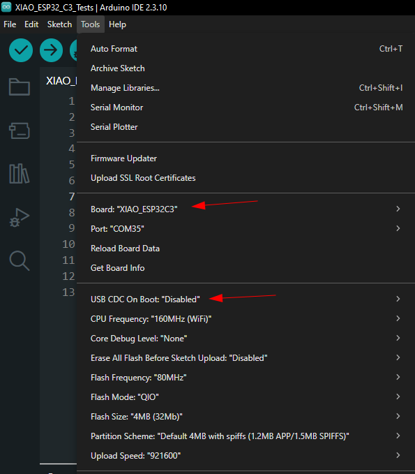
I am using Arduino 2.3.6. I changed the USB CDC mode to match yours but saw no change. Otherwise my settings match.
(I’m not allowed to upload images on this forum, my account is too new. But imagine a screenshot here of all my settings matching yours)
I think there is something physically wrong with my board. I have a second one I wired up the same battery to and an LED and it worked as expected. Putting that battery again back to my original board, I get nothing off battery power.
I’ll re-do the project another night, and start a new thread if I’m still stuck.
Thank you @PJ_Glasso and @grobasoz for your time. I do appreciate it.


 PJ
PJ