I’ve been developing a home made bike power meter and have something that mostly works, but the ANT communications seem to be a bit flaky.
I’ve just noticed that the suggested MISO and MOSI pins on the board are gpio 1.14 and 1.15 which are described as “Standard drive, low frequency I/O only” in the nrf52840 data sheet. I’m using those pins for SPI at 1Mhz (active for an 8 byte transfer once every 100ms).
Could this be causing interference? It seems strange that the board recommends those pins for SPI when they’re supposedly low frequency.
I’m mostly using vscode for development. It’s a SEGGER studio project using Nrf5 Sdk, but mostly I build using embuild, except when I need to use the debugger.
For the most part, ANT seems to be working; but I notice that there are short periods (up to about 10 seconds) where Garmin reports the power as zero when it clearly shouldn’t. And I’m recording per second data to the external flash on the board - so I can see that the device was trying to broadcast non-zero power during those times. I typically get one drop out like that every 15 minutes or so.
I’ve not been able to find a reason for this, so when I noticed the MISO/MOSI issue, I thought I’d ask.
As far as I’ve been able to determine, the only reason to restrict those pins to low frequency is to avoid RF interference. I’m just wondering if anyone has any experience of these pins actually causing a problem. If need be, I can redo my design - but that’s a lot of trouble if this is just a theoretical problem (or if I’ve misunderstood the data sheet). And presumably this was taken into consideration when picking those pins in the first place.
That is pretty odd - but it presumably explains why the xiao boards also do that.
That’s really odd - because the data sheet says those pins should be limited to 10khz signals.
Well I’m kind of cheating here. I’m using SPI to read data from an hx711. Yes, I know it’s not an SPI device, but you can send pulses to the hx711’s SCK pin over MOSI while reading DATA back over MISO and use an unconnected pin for SCK, and it all works out.
If you’re wondering why I’m doing that, it’s mostly because there’s no reliable way to use the cpu to generate gpio pulses that are guaranteed to be less than 50 micro-seconds wide while the soft device is running. There are various ways to use PPI and events to do so, but if I’m going to use the hardware to generate the pulses, I might as well use SPI and offload the whole thing from the cpu.
And however I do it, I have to generate pulses (and read back data) at roughly 1Mhz; way way higher than the 10khz we’re apparently supposed to limit these pins to.
No - but the SPI communication is working perfectly, so I don’t think that’s an issue.
it’s ANT that seems to have too many dropouts, and I was concerned that that was related to using low frequency pins for SPI.
In any case, I’ve now tried using P0.04 and P0.05, which are marked as external SCL and SDA on the Xiao schematics, and as regular (ie not low frequency) pins on the nrf52840 data sheet, and I got the same results, so this probably isn’t the issue…
SO there are some other makers using ANT on here, and I believe there are additional info’s out there as well, The nRF52840 has only one 2.4 GHz radio used for Bluetooth Low Energy (BLE), ANT, and other 2.4 GHz protocols [3]. These protocols are time-sliced by the soft device. The soft device guarantees radio timing and manages the transceiver. The takeaway from what you describe and those other symptoms seems to point at two things ? YMMV
Decoupling/Resistors: While your SPI comms are working, adding small series resistors (e.g., 22 Ohm to 47 Ohm) on high-speed lines can help with signal integrity and potential reflections, which might inadvertently help with overall system stability if there are any ringing issues affecting other radios (like ANT).
Radio Interference: The ANT dropouts are a separate concern. Your high-frequency SPI activity generates electromagnetic interference (EMI). While the signals themselves might be working, this noise could be coupling into the radio system and causing the dropouts. The fact that moving to P0.04/P0.05 didn’t resolve the ANT issue supports the theory that the issue is less about the specific GPIO registers and more about either:
General electrical noise from the ~1MHz SPI bus.
A software configuration conflict in how ANT and the SPI peripheral are initialized or scheduled.
The nRF52840 has a complex pin architecture. The limitation you read about likely refers to the use of certain GPIO pins as inputs when the High Voltage (H-VDD) is active, or perhaps relates to the specific capabilities of the secondary, low-frequency crystal oscillator (LFXO) pins if they are being repurposed as GPIOs [3].
P1.13, P1.14, P1.15: These pins on the nRF52840 are generally designated as regular GPIOs and should be capable of standard high-frequency operation when configured correctly. They can often handle the full system clock speed. The “10 kHz” limit is unusual for typical GPIO use and may require checking the exact datasheet conditions that impose this limit. Triple check that and verify for the Package they use in the Xiao …
Your use of the SPI peripheral as a pulse generator for the HX711 is a clever and valid technique for offloading the CPU in a soft-device environment. The current problem seems more likely to be an EMI or software coexistence issue rather than a fundamental pin frequency limitation
Debug ANT Dropouts:
The issue is likely related to the radio environment or timing. Monitor the ANT library event handler to see the nature of the dropouts (e.g., channel closed, timeout, etc.) [3].
Temporarily slow down your HX711 SPI frequency if possible to see if the ANT dropouts decrease. This would strongly indicate an EMI issue.
Ensure you are using the latest nRF Connect SDK (NCS) or nRF5 SDK version and review the examples for proper ANT peripheral coexistence
I’ll just say here that I have no reason to think that the issue is related to SPI, except for the data sheet saying that the pins I’m using (and the xiao ble sense documentation recommends) are low frequency only.
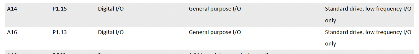
I’m prepared to believe you, but this is from nrf52840_PS_v1.11.pdf, “7.1.1 aQFN73 ball assignments”:
Note that lots of pins do not have the “Standard drive, low frequency I/O only” designation. If you’re right that they are as good as any other I/O, why are they documented this way?
I’ve just found an html version on Nordic’s site, so you can see the entire table here: Technical Documentation
My problem here is that the receiving device is a Garmin, and all I actually see is that the reported power goes to zero, and stays at zero for a few seconds.
If it wasn’t receiving anything for 2 seconds or more, it would report that it lost contact, try to reconnect, and report again when it reconnected (with a loud beep for each event). So I don’t think it’s actually disconnecting.
When I look at the data I recorded on the external flash, I see that my firmware was still sending (or at least thought it was sending) sensible values during those times.
For most of the ride, the data I recorded, and the data the Garmin recorded are the same. For a few short intervals, the Garmin got zero. It could be a bug in my firmware, but it’s a very odd one.
I’ve actually tried putting the bike on a bench, and turning the pedals by hand, with an ANT dongle listening to the transmissions, and I’ve not seen the issue (but my arms get tired!). I don’t have a portable device that can connect to the ANT dongle while I ride, so I can’t test that way on the road.
Good idea. That’s worth a try.
Yes. And it works well at home, talking to an ANT dongle. In fact, 99.9% of the time it’s working well on the bike…
@PJ_Glasso suggested slowing down the SPI frequency. I decided to go one better, and just turn it off. I put the HX711 into sleep mode by holding the MOSI pin high, and configured MISO as a disconnected input, and disabled SPI.
This meant I’m not getting torque data, so I simulated it, making it proportional to cadence (not realistic, but never mind).
And I got the same results. For most of the ride, the garmin data matched my simulated power data very closely, but for a couple of short sections, garmin reported zero when the simulated power was non-zero.
So at this point, I think I can say that the pin choice for MISO/MOSI is not relevant to the problem.
But I did get a bit further. This time I connected two Garmin devices during the ride. They both had the issue, but not at the same time - meaning that the data was definitely being transmitted, but not always received.
As I noted before, if the Garmin loses contact (no messages for 2 or more seconds), it reports the issue via an alert, and that doesn’t happen. But currently, only 2 or 3 out of every 5 messages actually carries power data - so it’s possible that with really bad reception, and bad luck, the Garmin might only receive the ancillary messages for a while, which keep the connection alive, but don’t convey power. I think that’s what must be happening.
I’ve just discovered that the default transmit power for the S340 is 0dBm, so my next test is to see if +8dBm improves things…
I’m surprised there could be a significant power saving…
My hx711 board draws around 500na in power down mode, and around 10ma when it’s running (this was measured with a PPK II).
The board is configured for an output of 3.08V, and the strain gauges are 350 Ohms, so 8.8ma should be going through the strain gauges - leaving about 1.2ma for the rest of the board. Even if the ADS1220 halves that, it’s only saving 0.6ma out of 10.
Props my guy Not just for the great Walk-through, but demonstrating reasoning and critical thinking, and your stuff is Funny Too
It’s very helpful too, for folks to see how to walk it through not to mention open for suggestions.. Great JOB! and Thanks for the contribution
Looking forward to the next test round
Crafty using a second unit , wowsa…
I wonder about the Garmin Spec and their hardware ? 2 seconds seems long , but not in Sat Data but comms , yes..too long of a drop out but not for a GPS update SMH
GL PJ
for anyone wanting more info, I AI’d some pertinent ANT info…
The ANT protocol stack excels in ultra-low power, long battery life for small sensors, efficient data transfer (especially fitness/cycling), easy proximity pairing, and interoperability through, ANT+ profilesmaking it ideal for connecting heart rate monitors, bike sensors, and wearables, even offering better mesh/multi-device handling than early Bluetooth LE in some fitness scenarios. Its advantages stem from a lightweight design and specialized network features, contrasting with Bluetooth’s higher speeds for broader IoT/smartphone use.
Key Advantages of the ANT Protocol Stack:
Ultra-Low Power: Consumes minimal battery, allowing devices (like coin-cell sensors) to last years, only drawing power during data bursts.
Efficient for Low Data Rates: Perfect for periodic sensor data (HR, cadence, power) in fitness/sports, requiring modest data rates (up to ~60 kbps).
Interoperability (ANT+): The managed ANT+ network uses standard profiles (e.g., HR Monitor, Bike Power) for seamless data exchange between different brands, creating robust ecosystems.
Easy Pairing & Ad-Hoc Networking: Simple, proximity-based pairing and flexible topologies (beyond simple star/peer-to-peer) simplify connecting new devices.
Robustness & Coexistence: Sophisticated mechanisms handle multiple devices and noisy 2.4GHz environments well, crucial for group fitness settings.
Simplified Development: Integrated protocol layers on chips let developers focus on application logic, speeding time-to-market.
ANT: Lower power, better for small sensors, excels in fitness ecosystems, simpler protocol.
BLE: Higher data rates, broader smartphone compatibility, better for general IoT/larger data.
Flexible Network Topologies: ANT supports various practical wireless sensor network topologies, including peer-to-peer, star, tree, and complex mesh networks. Any single node can act as both a master for one channel and a slave for another concurrently, allowing for complex and scalable network arrangements.
Interoperability (via ANT+): The ANT+ managed network defines specific device profiles (e.g., heart rate monitors, power meters, speed sensors) that ensure products from different manufacturers can communicate and exchange data seamlessly.
Efficient Coexistence and High Density: The protocol uses an adaptive isochronous mechanism where master devices can detect and adjust their transmission timeslots to avoid collisions with other signals. This allows hundreds of independent devices (e.g., in a large spin class) to operate in the same physical space without interference.
Lightweight and Small Footprint: The protocol stack has a small memory footprint, which minimizes the host microcontroller’s memory requirements and allows developers to focus more on the application layer, speeding up development cycles.
Proximity Pairing: The protocol includes built-in features for proximity-based pairing, which simplifies the user experience in crowded environments by allowing users to easily connect to the nearest device. this a cool feature
if you wan nordic’s take HERE is an older ANT webinar. Also a 10K foot view from a manufacture of Bike stuff for it ZBIKE_ANT
Awesome thread , I learned some things I did Not know they used, “Isochronous” I’m familiar I Haven’t heard that one since m\y Black Box Data-comm days..
This is just part of the ANT spec. If the message rate is less than 2Hz, it reverts to search after 4 consecutive missed messages. If the message rate is above 2Hz, it reverts after 2 seconds of missed messages. The ANT+ Bike Power protocol runs at 4Hz (or 8Hz for cycling dynamics).
I guess Garmin just passes that on to the user via a message on the display, and a beep.
Ads1220 has a duty cycle mode and a low side switch which combined helped me to almost half the current , my board was 8mA while running and broadcasting, now is 5.5mA.
This is wandering a long way from the original topic, but this is interesting, so…
So doesn’t that mean that the sensor is only measuring the output of the bridge for a portion of the sample time?
As I understand it, with the hx711 each output is essentially averaged over the full 100ms (my board is running at 10hz) - which is exactly what I need for cycling power. Yours is only measuring a portion of the interval. I guess in practice the applied force isn’t changing very fast, but wouldn’t the noise be higher with a shorter sample period?
For my project, I get about 40 hours of riding time from a single charge - and the draw is so low in power down mode that it doesn’t matter - so I think given a choice between lower power, and less noise, I’d take less noise…
Well setting the tx power to +8dBm seems to have fixed it.
Testing with an ANT dongle at home, at 0dBm (the default, and what I was using before), I start getting a significant number of dropped messages when the dongle is more than about 8ft from the board. At +8dBm it’s more like 12ft. That seems low, but I’ve read elsewhere that the antenna on the ble sense board is not very good.
But even 8ft is much further than the distance from my handlebars to the cranks. Maybe the Garmin’s sensor is less sensitive than the dongle; or maybe the vibrations when I’m riding affect the signal strength.
Just to wrap up, I’m pretty sure that the “low frequency I/O only” issue was unrelated to my actual problem.
But thinking about it a bit more, it is possible that SPI is causing RF interference, and I just wouldn’t notice.
In my project, SPI runs for about 28 micro-seconds, once every 100 milliseconds.
ANT transmissions run for about 150 micro-seconds, roughly once every 250 milliseconds.
So if collisions always resulted in a lost tx packet, it seems that worst case (if they were perfectly aligned), half the transmissions (0, 500ms, 1000ms, etc) would be lost - which would be pretty bad.
But the actual bike power tx period is 8182/32768. So if an ANT tx collides with an SPI packet at t=0, the next ANT tx will happen midway between two SPI packets, and the one after than will happen at t=0.499389s, which is 611 microseconds before the fifth SPI transfer occurs, and the two won’t interfere. The next one is again mid way, and the next is 1222 microseconds early… etc.
So the result is that IF using the default MISO/MOSI pins did interfere with ANT tx, that interference would only happen once every few hundred messages in my project, which simply wouldn’t be noticed (dropped packet rates below 10% are considered very good for ANT).
I’d already figured out empirically that it’s not affecting my project, and now (if my math is correct) this shows that it wouldn’t be a problem anyway.
I think it would have even less impact on BLE - if an occasional packet was dropped it would just be retransmitted (unlike ANT, ble verifies reception and retransmits).