Hello - I am trying to figure out how to read the current battery charge level via the Xiao BLE Sense with a 3.7V Lipo battery connected via JST to the Xiao Expansion Board. However, I am confused by the various discussions around this topic in the past and the apparent lack of a clear solution (suggesting this is not as straightforward as expected). I got closest by following msfujino’s guidance in this thread ( How do I get an info about battery percentage that powering up the Arduino - #5 by kamrynl ) but I am not getting useful data (values fluctuate 3.7 - 4.1V and show the same pattern even when the battery isn’t even plugged in.
Is there a clear solution available? Am I getting the issue because the battery is connected via JST instead of soldered directly on the BLE Sense? If yes, is there a way to read the battery levels when connected via the JST / Expansion Board?
Thanks a lot in advance!
Please take a look at the image in Post #1 at the link below.
The battery voltage connected to the JST connector on the XIAO Expansion Board is not directly connected to the XIAO. Some modifications are required to read the voltage.
Thank you! I will give it a try. Is the mbed-enabled strictly necessary if I only want to read the battery or was this limited to other parts of your reference project? My own project is running non-mbed
I have tried to extract the relevant portions of your reference program for the battery reading only (thanks again for the guidance!).
I am using the below sketch (mostly extracted from your reference file) which compiles properly. However, when trying to read the battery I am only getting a reading of ~“0.15L” which is clearly lower than the battery’s actual charge status (which should be close to full for a 3.7V LiPo battery). I currently have the battery connected via the Expansion Board’s JST connector.
Any chance you can help me clarify my confusion? I was unable to apply your patch as it related to mbed-based files whereas the below sketch is non-mbed based (as I will need to feed it into a larger sketch).
#include <Arduino.h>
#include <Wire.h>
#include <U8x8lib.h>

#define VBATT          A3     //Central battery voltage (voltage divider required on XIAO Expansion Board)
#define VBAT_LOWER    3.5     //battery voltage lower limit

float Vbatt;                  //Central battery voltage (voltage divider required on XIAO Expansion Board)

U8X8_SSD1306_128X64_NONAME_HW_I2C display(/* reset=*/ U8X8_PIN_NONE, /* clock=*/ D5, /* data=*/ D4);

void setup()
{
  //Serial port initialization
  Serial.begin(115200);
  delay(1000);

  // This starts up the screen so it's ready to receive text
  display.begin();
  display.setFont(u8x8_font_chroma48medium8_r);
}

void loop()
{
//averages the battery voltage 32 times
    int Vadc = 0;
    for (int i = 0; i < 32; i++) {
      Vadc = Vadc + analogRead(VBATT);
    }
    Vbatt = 1.000 * 1.33 * 3.6 * (Vadc / 32) / 4096;  //sample:correction value=1.000, Vref=3.6,attenuation ratio=1.33

    display.clear();
    display.setCursor(0, 0);

display.print(Vbatt, 2);
      if(Vbatt < VBAT_LOWER) {
        display.print("L");
      } else {
        display.print("V");
      }

    delay(1000); // wait a second before the next reading
}
Thanks a lot in advance for any help!
The link I provided is for the nRF52840. I’ve made the necessary adjustments to adapt it for the XIAO_BLE_Sense (SAMD21).
#include <Arduino.h>
#include <Wire.h>
#include <U8x8lib.h>
#include <ATSAMD21_ADC.h>

#define VBATT          A3     // Central battery voltage (voltage divider required on XIAO Expansion Board)
#define VBAT_LOWER    3.5     // battery voltage lower limit

float Vbatt;                  // Central battery voltage (voltage divider required on XIAO Expansion Board)

U8X8_SSD1306_128X64_NONAME_HW_I2C display(/* reset=*/ U8X8_PIN_NONE, /* clock=*/ D5, /* data=*/ D4);

void setup()
{
  // Serial port initialization
  Serial.begin(115200);
  delay(1000);

  // ADC configuration
  analogCalibrate();                    // Import factory calibration values  ATSAMD21_ADC.h
  analogReadExtended(16);               // Average 256 samples using 16-bit precision

  // This starts up the screen so it's ready to receive text
  display.begin();
  display.setFont(u8x8_font_chroma48medium8_r);
}

void loop()
{
  // correction value=1.000, Vref=3.3,attenuation ratio=1.33
  // Corrections are necessary to obtain accurate values.
  // It is affected by the stability of the 3.3 V supply.
  Vbatt = 1.000 * 1.33 * 3.3 * analogRead(VBATT)/65536;

    display.setCursor(0, 0);
    display.print(Vbatt, 2);
      if(Vbatt < VBAT_LOWER) {
        display.print("L");
      } else {
        display.print("V");
      }

    delay(1000); // wait a second before the next reading
}
I think I might be misunderstanding something. Is the XIAO you’re using an nRF52840?
Since a buzzer circuit is connected to A3, it can’t be used for the battery voltage ADC. I recommend using A0.
Yes, the XIAO is using the nRF52840 chip.
I tried switching to A0 but it still shows the same (<0.1L despite a near-full battery)… which means it does pick up something but not the battery itself. I tried looking in the Expansion Board intro but it doesn’t appear to link directly the LiPo battery input to a specific pin (link: Expansion Board Base for XIAO | Seeed Studio Wiki)?
I wish the new expansion board would have a battery management chip on an IIC line
not sure if you have seen this.
To summarize, what you are trying to do is create a analog sense of a voltage divider circuit.
The exact reading of the voltage directly is not possable. You have to map the ADC to a calculated voltage based on calibration by trial and error. This requires an understanding of how ADC work… Voltage Reference line and This is why it is difficult to answer your question… HTH
Thanks a lot for the input. I am very new to this whole world with no real prior knowledge so I don’t think this sounds feasible to me.
Does this essentially mean there is simply no simple / established way to measure the battery charging level for Seeed / Arduino projects? How do you deal with this in your everyday projects - just hope it won’t run out?
Sorry for the ignorant question, I am just honestly baffled why something that seemingly sounds so simple appears to be so complicated!
yes… we have been wanting this forever… the basic answer is that if voltage management was a standard thing… it would take away a GPIO pin from the board that someone else might really need… so you have to mangage this off board. It is really not that complex a concept… you just have to research and learn it yourself… It will be a rewarding learning experience… we just dont have the time to teach you… please google and watch youtube video on ADC analog to digital converters and voltage dividers and you will understand… i recomend experimenting with a analog potentiometer
SeeedNoob,
I mistook it for the SAMD21 and accidentally sent the wrong example.
The attached sketch is currently running on an expansion board connected to a battery right here on my desk. It definitely works.
However, on my expansion board, 1000k and 680k resistors are connected to pin A1. The comments aren’t in English, but please use this as a reference.
nRF52_XIAO_EXP_BatteryMonitor.zip (4.2 KB)
- This is a basic point, but the slide switch is turned on, right?
- Which pin did you add a resistor of how many ohms to?
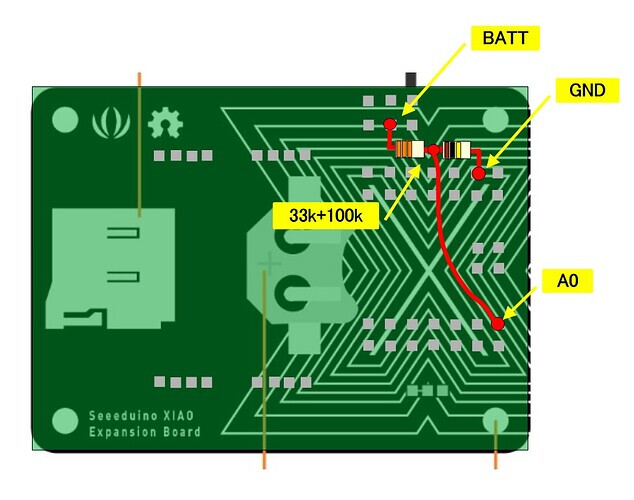
Thank you very much for the updated sketch and the schematic - let me try again and report back as soon as I managed to (as I’m currently away from my project)!
One question I didn’t fully get - your code (and schematic) references usage of voltage dividers but I couldn’t see those in the photos you posted on the sleep apnoea project. Is that just because they sat on the other side of the Expansion Board and hence weren’t visible? If so, would you be able to show how the connections look like in “real life”? Thanks a lot in advance!
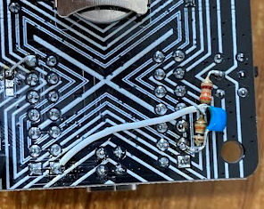
 PJ
PJ 
Thank you so much! Will report back as soon as I was able to look at it
It worked! Thanks a lot for your help - pasting below the final code I am running for future reference (I only removed the SD card portion of your code before.
//----------------------------------------------------------------------------------------------
//Board Library : Seeed nRF52 Borads 1.1.8, 1.1.9
//Board Select  : Seeed nRF52 Borads / Seeed XIAO nRF52840 Sense
//2023/06/12 動作確認済み
// 2025/01/31 @msfujino
//----------------------------------------------------------------------------------------------
//#include <Arduino.h>
//#include <Adafruit_TinyUSB.h>   //【重要】忘れるな!!! 多分必要ない

#include <Wire.h>
#include <SPI.h>
#include <Adafruit_GFX.h>
#include <Adafruit_SSD1306.h>
#include "Fonts/FreeSans9pt7b.h"
#include "Fonts/FreeSerif9pt7b.h"

//ピンの定義
#define ADC_IN      A1      //ADC入力   バッテリ電圧分圧器(公称1MΩ、680kΩ)に接続 ADC入力インピーダンス >1MΩ

//OLEDの定義
#define OLED_WIDTH 128      //OLED 表示幅
#define OLED_HEIGHT 64      //OLED 表示高さ

//クラスのインスタンス生成
Adafruit_SSD1306 display(OLED_WIDTH, OLED_HEIGHT, &Wire, -1);    //SSD1306のインスタンス

//定数の定義
#define versionNumber "1.00"    //バージョン番号
#define LOGINTERVAL    60*1000  //データを更新する間隔 mS
#define UPPERLIMIT    4.100     //電圧上限(表示のみ)
#define LOWERLIMIT    3.700     //電圧下限(表示のみ)
#define AVENUM          256     //ADCの平均回数

//変数の定義
uint32_t  measureTime = millis();            //測定時刻
uint32_t  before_measureTime = millis();     //前回の測定時刻
uint32_t  interval;                          //ログ間隔
uint32_t  Vadc;                              //ADC値12ビット 平均化のため積算する 32ビット
float     Vbatt;                             //バッテリ電圧
float     before_Vbatt;                      //前回ログしたときのバッテリ電圧
float     delta_Vbatt;                       //前回ログしたときからのバッテリ電圧の変化
String    Vstate;                            //バッテリの状態 Low Good High
bool      led_OnOff = false;                 //LED ON/OFFフラグ

//******************************************************************************************************
void setup()
{
  //シリアルポートの初期化
  Serial.begin(115200);
//  while(!Serial) {;}

  //ピンのモード設定
  pinMode(ADC_IN, INPUT);            //ADC入力
  pinMode(LED_RED, OUTPUT);             //LED 点灯はLOW
  pinMode(LED_GREEN, OUTPUT);
  pinMode(LED_BLUE, OUTPUT);

  digitalWrite(LED_RED, HIGH);          //LED 消灯
  digitalWrite(LED_GREEN, HIGH);
  digitalWrite(LED_BLUE, HIGH);

  //ADCの初期化 wireing_analog_nRF52.c
  analogReference(AR_DEFAULT);      //デフォルトは0.6V*6=3.6V±3%
  analogReadResolution(12);         //10, 12, 14
  analogSampleTime(40);             //3(10k), 5(40k), 10(100k), 15(200k), 20(400k), 40(800k) 6.23.1.1 Aquisition time

  //ディスプレイSSD1306の初期化
  Wire.begin();   // デフォルトでも指定しても400kHzになる

  if(!display.begin(SSD1306_SWITCHCAPVCC, 0x3C))        //表示用電圧発生
  {
    Serial.println("SSD1306の初期化失敗");
  }
  Serial.println("SSD1306初期化終了");
  display.clearDisplay();
  display.setFont(&FreeSerif9pt7b);
//  display.setTextColor(SSD1306_WHITE);  //指定しなくても問題ない
  display.setCursor(0, 15);
  display.println("SSD1306 init");
  display.display();
  delay(1000);

  //タイトル、情報の表示
  display.clearDisplay();
  display.setFont(&FreeSerif9pt7b);
  display.setTextColor(SSD1306_WHITE);
  display.setCursor(0, 15);
  display.println("Battery Monitor");
  display.setCursor(0, 31);
  display.println("   Data Logger");
  display.setCursor(0, 47);
  display.print("Ver   : ");
  display.println(versionNumber);
  display.display();
  delay(5000);
  display.clearDisplay();

  Serial.println("初期化の終了");
}

//************************************************************************************************
void loop()
{
  digitalWrite(LED_RED, led_OnOff);    // LOOP毎に赤LED点滅
  led_OnOff = !led_OnOff;

  //バッテリ電圧を平均化して求める
  Vadc = 0;
  for(int i = 0; i < AVENUM; i++)
  {
    Vadc = Vadc + analogRead(ADC_IN);
  }
  Vadc = Vadc / AVENUM;
  Serial.println(Vadc, HEX);
  float Vbatt = 1.68 * 3.6 * Vadc/4096 * 0.97; // 公称Vref=3.6  公称分圧比=1.68 補正:正確にはデバイスごとに異なる
//  float Vbatt = 1.33 * 3.6 * Vadc/4096;

  if(Vbatt <= LOWERLIMIT)
  {
    Vstate = "Low";
  }
  else if(Vbatt >= UPPERLIMIT)
  {
    Vstate = "High";
  }
  else
  {
    Vstate = "Good";
  }

  //データの取得時刻 データロガー用
  measureTime = millis();
  interval = measureTime - before_measureTime;

  if(interval >= LOGINTERVAL)
  {
    before_measureTime = measureTime;
    delta_Vbatt = (Vbatt - before_Vbatt) * 1000;
    before_Vbatt = Vbatt;
  }

  //データの表示
  display.clearDisplay();
  display.setCursor(0, 15);
  display.print("Volt"); display.setCursor(63, 15); display.println(Vbatt, 3);
  display.setCursor(0, 31);
  display.print("mV/min"); display.setCursor(63, 31); display.println(delta_Vbatt, 3);
  display.setCursor(0, 47);
  display.println("mS");
  display.setCursor(63, 47);
  display.print(interval);
  display.setCursor(0, 63);
  display.print(Vstate);
  display.setCursor(63, 63);
  display.println(Vadc);
  display.display();

//  delay(10);
//  digitalWrite(PIN_LED, HIGH);
//  delay(10);
}
I’m glad I could be of help.