Hi, I am getting custom designed xiao ble without reset button on it. Will it come with bootloader or not. if not how can i install bootloader in it without reset button
Hi there,
Good for you, ![]()
![]() ,well the Programmer certainly can put the MCU into boot mode and write anything to it you need? Boot-Loader, Softdevice, Application, whatever.
,well the Programmer certainly can put the MCU into boot mode and write anything to it you need? Boot-Loader, Softdevice, Application, whatever.
and soft reset also.
HTH
GL ![]() PJ
PJ
I did not have any idea about that can you share any resource for it .
will i need to do bootloader it will come with bootloader?
and is it possible to flash bootloader using jtag swd pins or using other board
Hi there,
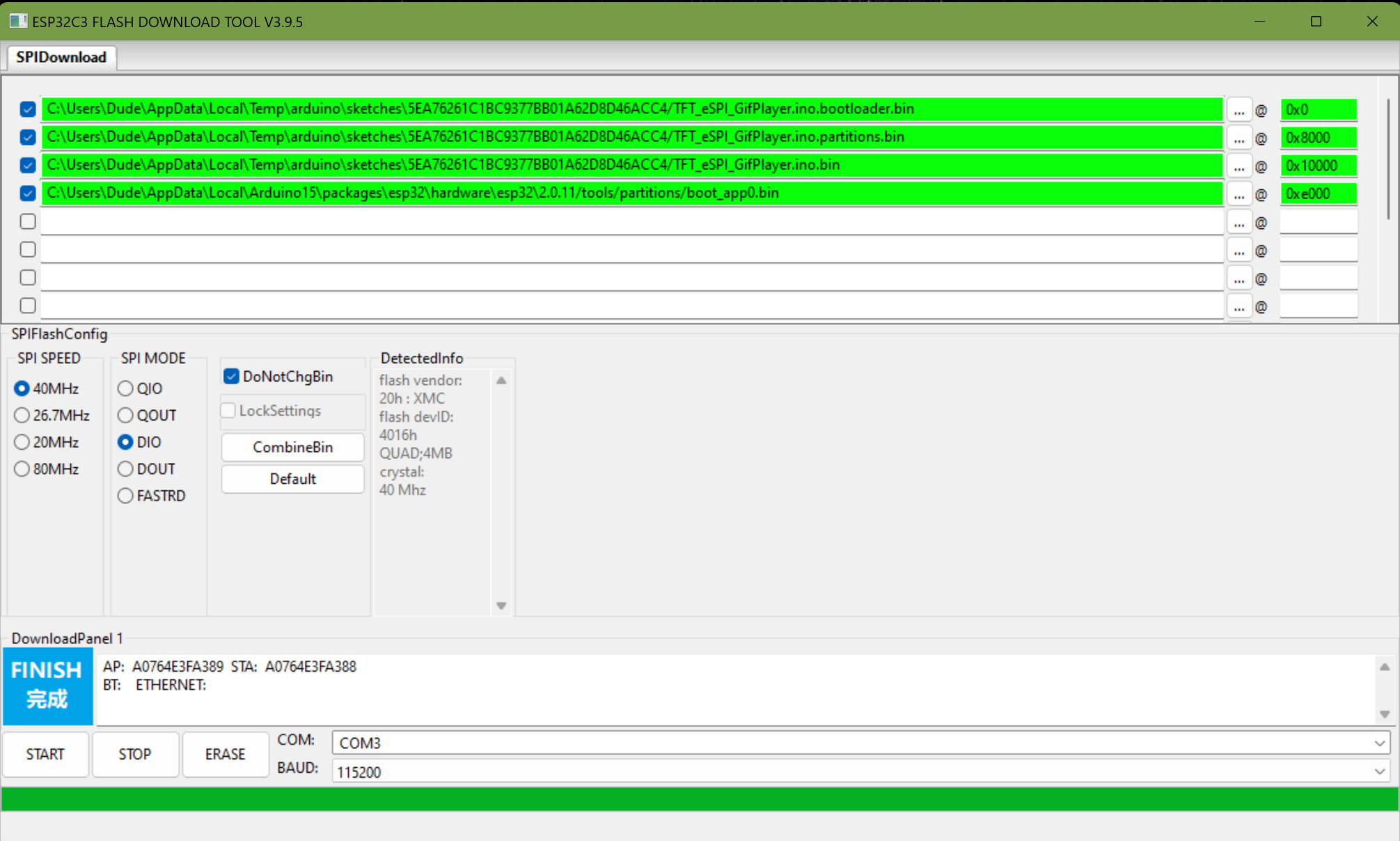
Sure , check out the Creating a standalone bin file. demo
I don’t know about what yours comes with , So send them an E-mail and ask?
Yes Flashing bootloader is part of if you want it as part of the process.
You may not need it for production. just the Softdevice and APP
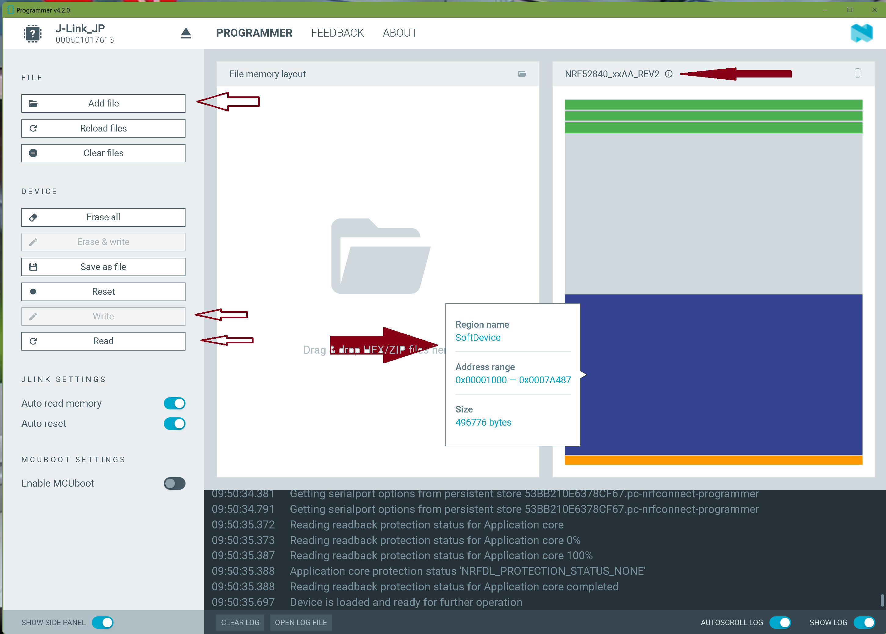
Reading the chip you see the different partions.
Note the NAMES in each file that’s combined, just like when you press upload in arduino IDE.
There’s tons of video’s about the BOOT loaders for allot of MCU’s adafruit has a series also, as well as NRF52.
HTH
GL ![]() PJ
PJ
The following table shows the memory layout for the different chips with current SoftDevices:
| Usage | Memory range nRF52832 (S132 v6.1.x) | Memory range nRF52840 (S140 v6.1.x) | Memory range nRF52810 (S112 v6.1.x) |
|---|---|---|---|
| Bootloader settings | 0x0007 F000 – 0x0008 0000 (4 kB) | 0x000F F000 – 0x0010 0000 (4 kB) | 0x0002 F000 – 0x0003 0000 (4 kB) |
| MBR parameter storage | 0x0007 E000 – 0x0007 F000 (4 kB) | 0x000F E000 – 0x000F F000 (4 kB) | 0x0002 E000 – 0x0002 F000 (4 kB) |
| Bootloader | 0x0007 8000 – 0x0007 E000 (24 kB) | 0x000F 8000 – 0x000F E000 (24 kB) | 0x0002 8000 – 0x0002 E000 (24 kB) |
| Application area (incl. free space) | 0x0002 6000 – 0x0007 8000 (328 kB) | 0x0002 6000 – 0x000F 8000 (840 kB) | 0x0001 9000 – 0x0002 8000 (60 kB) |
| SoftDevice | 0x0000 1000 – 0x0002 6000 (148 kB) | 0x0000 1000 – 0x0002 6000 (148 kB) | 0x0000 1000 – 0x0001 9000 (96 kB) |
| Master Boot Record (MBR) | 0x0000 0000 – 0x0000 1000 (4 kB) | 0x0000 0000 – 0x0000 1000 (4 kB) | 0x0000 0000 – 0x0000 1000 (4 kB) |
GL ![]() PJ
PJ

Hi there,
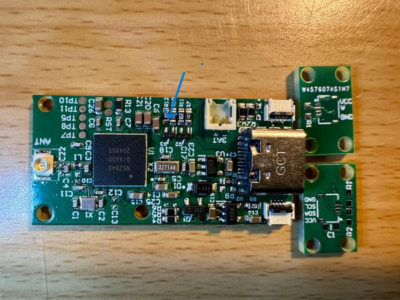
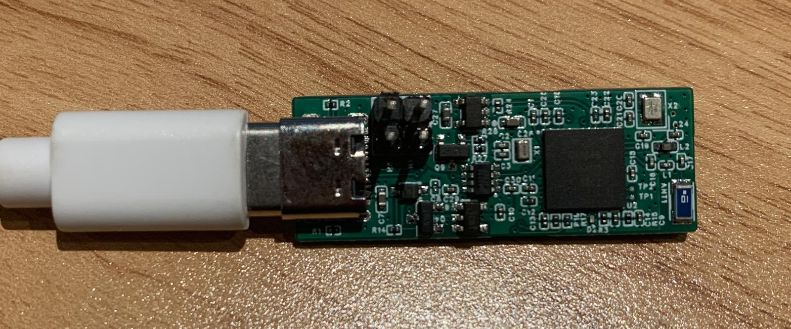
WOW ,Congrats ![]() . That is a Beautiful Thing Brother
. That is a Beautiful Thing Brother ![]()
![]()
And Yes No bootloader… correct.
Use a nordic one or? Adafruit.
HTH
GL ![]() PJ
PJ
ps. this looks a little tight? is it ok? (Blue Arrow) they look to be touching?
Nordic nrf52840 one used. Forbootloader flash jlink box needed or any other?
hi there, Yea , or the Mini, or even better is the Nrf52840DK has it built in for $50
Connecting to target via SWD
InitTarget() start
InitTarget() end - Took 5.36ms
Found SW-DP with ID 0x2BA01477
DPv0 detected
CoreSight SoC-400 or earlier
Scanning AP map to find all available APs
AP[0]: Stopped AP scan as end of AP map has been reached
Iterating through AP map to find AHB-AP to use
Attach to CPU failed. Executing connect under reset.
RESET (pin 15) high, but should be low. Please check target hardware.
DPv0 detected
CoreSight SoC-400 or earlier
Scanning AP map to find all available APs
AP[0]: Stopped AP scan as end of AP map has been reached
Iterating through AP map to find AHB-AP to use
Could not find core in Coresight setup
Connect fallback: Reset via Reset pin & Connect.
RESET (pin 15) high, but should be low. Please check target hardware.
InitTarget() start
InitTarget() end - Took 9.09ms
Found SW-DP with ID 0x2BA01477
DPv0 detected
CoreSight SoC-400 or earlier
Scanning AP map to find all available APs
AP[0]: Stopped AP scan as end of AP map has been reached
Iterating through AP map to find AHB-AP to use
Attach to CPU failed. Executing connect under reset.
RESET (pin 15) high, but should be low. Please check target hardware.
DPv0 detected
CoreSight SoC-400 or earlier
Scanning AP map to find all available APs
AP[0]: Stopped AP scan as end of AP map has been reached
Iterating through AP map to find AHB-AP to use
Could not find core in Coresight setup
Cannot connect to target.
after 1 success it is not doing anything
After disconnecting jtag device picked up by Arduino ![]()
Can you share embed version ble with deepsleep code?
Hi there,
Awesome you got it going… The sleep code is here on the Grove Expansion Board Flash test thread with deep sleep push-button sleep/wake.
HTH
GL ![]() PJ
PJ ![]()
I encountered a very similar issue. I designed a custom PCB using the XIAO BLE Sense (nRF52840), but my PCB manufacturer wasn’t able to pre-burn the bootloader before soldering the nRF52840 chip.
After going through this thread, I tried using the nRF Connect for Desktop app, but none of the tools inside could detect any device when I scanned — even with USB connected. I’m wondering, how did you manage to get past this step?
Is it possible to flash the bootloader using only the USB-C connection without desoldering the chip? Any guidance or experience on this would be really appreciated!
Thanks in advance!
Hi there,
and welcome here…
So No , you can’t change the Bootloader with the USB, You need a SwD access. If you plug in the USB, does the computer Detect it with the USB new device Ding? , did you mind the Strapping Pins on the NRF PCB? (the table in the Wiki)
Are you able to enter BL mode (fast double reset push) ?
HTH
GL ![]() PJ
PJ ![]()
Check out my thread on Making a Production BIN file , or drag and drop Testing UF2.
Thanks for the warm welcome!
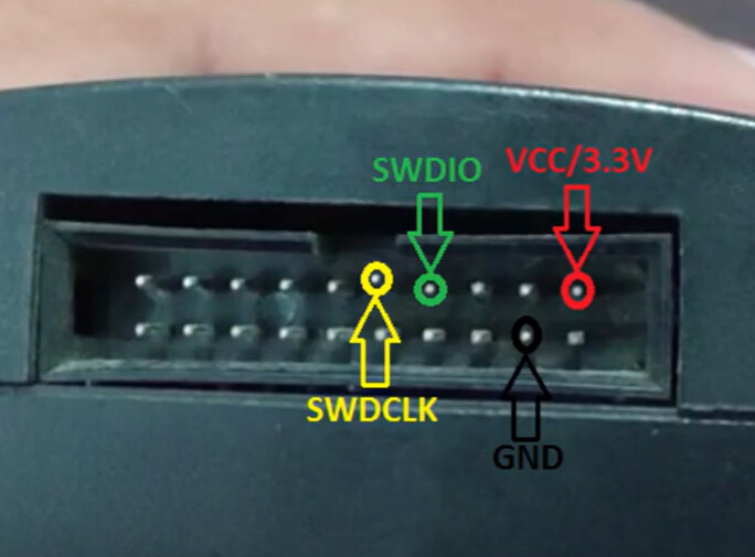
After posting, I did some more research (please correct me if I’m wrong) — it seems that all I really need is a SWD/JLink programmer and to connect the VCC, GND, SWDIO, and SWDCLK pins. I’ve just ordered a JLink v9, so fingers crossed it works when it arrives.
“If you plug in the USB, does the computer detect it with the USB new device Ding?”
No — that’s actually what made me suspect the board didn’t come with a bootloader in the first place.
“Are you able to enter BL mode (fast double reset push)?”
Unfortunately, I didn’t include a physical reset button on the PCB. Definitely something I’ll add in the next revision.
As for the Production BIN file or drag-and-drop UF2 testing — I assume those wouldn’t work unless the board is already being detected over USB, right?
Appreciate all the tips! Looking forward to getting the JLink hooked up and seeing if I can bring this board to life.
1 Like
HI there,
Very Good. Yes , there are some threads on here so check those out, You can download the Adafruit(Seeed Ships with) Bootloader and flash it Via , SWD to the Xiao and get the (double reset-fast) bootloader mode back. Send it a BLINK test or better yet when you get to bootloader mode successfully , drag & Drop the RGB_TEST.Uf2 file (from the test thread)RGB_Blink_test
after it completes It will reset and start Blinking RGB colors on the user LED.
HTH
GL ![]() PJ
PJ ![]()