Video waveform monitor

Hi,

Would it be technically feasible to develop a video waveform monitor application for these? The purpose of a WFM is to evaluate exposure in a video signal, and they’re used in all sorts of situations. The tiny DSO Quad scope would be a great portable device for use on location shoots.

A traditional CRT scope will behave as a waveform monitor without modification. Trigger on the line synchronisation pulses, and the display becomes a composite of luminance values of all the lines in the picture. It looks something like this:

The worst case scenario is that the HD video signal has 1080 lines at up to 30 frames per second, and assuming we wanted 360 samples per line, that’s a total of 11M samples per frame to put together for the display. This would of course challenge the analog bandwidth that’s available on the Quad, but it’s close enough that I’m encouraged it could be useful.

I appreciate it’s a bit of a broad question, but what would it take to do this? I understand what it needs to do programatically, but I have no background in embedded systems development.

HF

Should be doable; maybe not possible to capture every line, but most of them atleast. To capture all of them, a custom FPGA image could be used.

You could get started with Pawn:
github.com/PetteriAimonen/QuadPawn

See for example signlgen.pawn for how to draw screen quickly with putcolumn().

I intend to add custom FPGA support to Pawn eventually, but can’t promise any schedule :slight_smile: In the meantime, it’ll be only slightly slower than native C code would be.

Thanks for the response, I’ll look into it immediately!

This actually looks like it’s at my level of software engineering - I’ve done a bit of C# and Javascript and it seems somewhat comparable in that it’s fairly high level. I do worry slightly about the performance; is this compiled to a native executable, or are you running some sort of interpreter on the DSO’s Arm?

The big performance issue is that ideally, each video scanline would be written to the display at a low intensity, and additively with whatever comes before. As you can see in my demo image, a waveform monitor is ideally capable of variable intensity display. I’m not sure if it’s capable of doing that many adds. I notice blend(), but I’m not sure how fast it would be to draw entire displays like that at, hopefully, 20-30fps. Is the hardware even capable of variable intensity graphics, or is it just LUT colour?

Would it be better to create this image in memory somewhere and then put it on the display?

I guess that might require new native code.

Yeah, it is interpreted… about 4-10x slower than native. On the other hand the slowest parts such as display drawing and wave capture are written in C, so the total impact is not as large.

Hardware can do variable intensity, 16-bit colors in RGB565 format.

It would, but the processor does not have enough RAM. You would have to use some 100 x 50 pixel buffer, which might be accurate enough.

Maybe you could just keep average, min and max?

It really does need that variable display. Doing a “maximum value” would require keeping a table of all the previous scanline values at that sample, and calculating whether a particular sample was the biggest. Or, you could just write all the scanlines to the display, but again that would require a non-destructive putcolumn() which added to the existing frame buffer.

Looks like I might end up having to do it in C, then. Is the frame buffer accessible as memory in C, or is it specialised?

What’s the easiest way to write C for the DSO? I’m not very experienced in C.

This really is an FPGA application, isn’t it…

Well… there is a getcolumn() also. But it will be quite slow if for every scanline you read and update all the lines on the screen… using putpixel() might work though.

You could keep an array (400 items or so) of the maximum values, and update that for every scanline. Then once in a while draw that to the screen.

Nope, frame buffer is in the LCD’s own memory.

I don’t think C will simplify any of the difficulties here… it might improve the eventual performance a little, but the fundamental problems are the same.

I guess what I’m asking is whether the code underlying getcolumn() is in itself slow; if it isn’t, an additive putcolumn() could be written, although doing 240 adds on RGB565 data at, say, 5MHz might be an FPGA job in itself…

Oh, edit: this doesn’t actually have to be a full colour display. It would be OK to have the waveform display in a limited number of shades (say, 16). So, if a four-bit frame buffer could be created in RAM, that might be an OK approach.

The code isn’t slow, but it needs to fetch the data from the LCD; that does take some time, about 4 clock cycles per pixel; so about 13µs per column, and that is only half of the task.

Right, OK, understood.

See my edit above about a low-depth display option, though.

Yeah… well, there is one drawback with Pawn that you can avoid with C: with Pawn the program itself also takes up some RAM.

Anyway there is only 36kB of RAM available for applications, so a 400x240 pixel framebuffer won’t quite fit, except in monochrome. But I guess full resolution is not strictly mandatory for this kind of application, so you could get by.

Yet another approach would be to capture e.g. 10 scanlines at a time in RAM (they will fit easily) and then do the getcolumn()/putcolumn() cycle once for the group of 10.

Hm, well, even a 4-bit frame buffer at 240x400 is nearly 47kB, so that’s out.

If it was done on the FPGA, that has some internal RAM, but it’s looking non-doable in software.

There is only like 9kB of RAM on the FPGA. But I believe it is possible to do in software well enough to be usable. One could for example have binary framebuffer per each video frame, and then use the LCD ram for fading the older values.

Just to clarify

We’re not trying to integrate over many frames, we’re just trying to add each line to a single frame, but the issue is much the same. If we can’t have even a low-depth mono frame buffer, it can’t be done.

Further to our earlier convesation.

You implied that a monochrome frame buffer might be possible. The thing is, even assuming 4-bit, 16-greyscale (or greenscale!) operation, that works out to (2404004)/8/1024 = 46.875kB of RAM, which isn’t available.

Am I overlooking something? Because this would make it possible.

About the alternative approach of summing up 10 scanlines then writing frame buffer info for each:

Assuming we grabbed every fourth scanline, which would probably be acceptable, that means 240 scanlines per frame, ten scanlines per buffering period, and thus 240/10=24 retrievals of all columns from the TFT per frame. Assuming 25fps that means 2425=600 getcolumn() calls per second. At 240 pixels per column, assuming your estimate of 4 ARM cycles per pixel, that’s 600240*4 = 576,000 cycles per frame just spent retrieving data from the TFT, which is not feasible.

So, this is not going to work either, again unless I’m overlooking something.

Is getpixel() slow? Does it just call getcolumn() behind the scenes? Because if it’s reasonably fast, that would work too.

Edit: a 200x120 (half-resolution) 4-bit greyscale image is just about acceptable and would require 11k of RAM; am I likely to have 11k of RAM available after the Pawn interpreter is running? Would there be enough CPU time to blow this image up to the display, nearest-neighbour style?

Getpixel() and setpixel() make just one transfer from the LCD, so they are faster than getcolumn() and putcolumn(). Get/setpixel is about 4T, whereas getcolumn/putcolumn are about 240T, where T is about 0.1µS (haven’t measured).

Yeah; the pawn interpreter itself doesn’t take much ram, most goes for program code and data. The freq resp application has 18kB of data, and it also has quite complex graph drawing code (drawing adjustable scales etc.).

Scaling up in X-direction is easy, because you can just call the same putcolumn() for two X-coordinates. Y-direction takes more time, but on the other hand you have to mangle the data anyway to convert 4bit -> 16bit. Should be fast enough to redraw display at 25 FPS or more.

Thanks again for your help.

I’ve downloaded your Pawn interpreter and loaded it onto the DSO; all seems to be going well, and the frequency response app works fine. I’ll get stuck in and see what I can achieve.

I’m sure I’ll have to bother you again - I’ve never written Pawn in my life, but I’ve done a bit of C# and Javascript and it shouldn’t be the end of the world.

The part I’m most worried about is that I need to figure out how to differentiate line and frame syncs. They’ll both trigger the scope nicely on a rising-edge mode, the difference being that frame syncs are longer. Is there some way I could get the DSO to detect the length of a pulse?

HF

Yeah, you get the wave data in an array. You can just check if array[20] > threshold or similar to see if the pulse was longer than 20 samples (for example).

I’ve been trying to figure out how to get the best resolution of data about video waveforms, so I can set the scope up to read video in software.

This image shows one line of a colour bar signal at 0.2V/div:

Clearly the resolution isn’t very good. Let’s try the next option up, 0.5V/div:

…and we can’t see the brightest white part of the waveform, because it’s using so much space to show the negative-going part of the sync pulse.

I can do better with AC coupling, but that will cause huge inconsistencies as the average brightness of the picture changes.

Is this an intrinsic limitation on how the DSO works, or is there something I’m overlooking?

H
IMAG002.png
IMAG001.png

Hi,

There is actually a bit more data than the main app will show. The values from ADC are 8-bit (0 to 255 values), whereas the screen is only 240 pixels high and the display area only 220 pixels. So the signal in picture 2. may in fact fit to the range.

On the other hand, if you have to go with half-resolution framebuffer anyway, the 1. waveform is also accurate enough.

I notice what appears to be an interesting quirk.

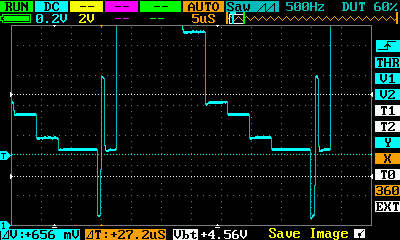
If I display the colour bar waveform at 0.2V/div, the top is clipped off:

If I export that waveform to a CSV, it retains the clipping - no value in the CSV data goes above 200, where the bottom of the sync pulse is at around 8.

Am I doing something silly, or is the CSV output limited to what’s displayable, as opposed to what’s actually in the sample buffer?

Here’s the sample data for one line of colour bars, 0.2V/div, 5uS/div, track one only:

TRACK1 50mV,TRACK2 ,TRACK3,TRACK4, 008,095,060,010, 008,095,060,010, 008,095,060,010, 146,095,060,010, 148,095,060,010, 146,095,060,010, 145,095,060,010, 073,095,060,010, 072,095,060,010, 073,095,060,010, 073,095,060,010, 074,095,060,010, 074,095,060,010, 074,095,060,010, 074,095,060,010, 074,095,060,010, 074,095,060,010, 074,095,060,010, 073,095,060,010, 199,095,060,010, 199,095,060,010, 199,095,060,010, 199,095,060,010, 199,095,060,010, 199,097,060,010, 199,097,060,010, 199,095,060,010, 199,095,060,010, 199,095,060,010, 199,095,060,010, 199,095,060,010, 199,095,060,010, 199,095,060,010, 199,097,060,010, 199,097,060,010, 199,095,060,010, 199,095,060,010, 199,095,060,010, 199,095,060,010, 199,097,060,010, 199,095,060,010, 199,095,060,010, 199,095,060,010, 199,095,060,010, 199,095,060,010, 199,095,060,010, 199,095,060,010, 199,095,060,010, 199,095,060,010, 199,095,060,010, 199,095,060,010, 199,095,060,010, 199,095,060,010, 199,095,060,010, 199,095,060,010, 199,097,060,010, 199,097,060,010, 199,095,060,010, 199,095,060,010, 199,095,060,010, 199,095,060,010, 199,095,060,010, 199,095,060,010, 199,095,060,010, 199,097,060,010, 199,095,060,010, 199,095,060,010, 199,095,060,010, 199,095,060,010, 199,097,060,010, 199,095,060,010, 199,095,060,010, 199,095,060,010, 199,095,060,010, 199,095,060,010, 199,095,060,010, 199,095,060,010, 199,095,060,010, 199,095,060,010, 199,095,060,010, 199,095,060,010, 199,095,060,010, 199,095,060,010, 199,095,060,010, 199,095,060,010, 192,095,060,010, 191,095,060,010, 191,095,060,010, 191,095,060,010, 191,097,060,010, 191,095,060,010, 191,095,060,010, 191,095,060,010, 191,095,060,010, 191,095,060,010, 191,095,060,010, 191,095,060,010, 191,097,060,010, 191,095,060,010, 191,095,060,010, 191,095,060,010, 191,095,060,010, 191,095,060,010, 191,095,060,010, 191,095,060,010, 192,095,060,010, 191,095,060,010, 114,095,060,010, 118,095,060,010, 120,095,060,010, 120,097,060,010, 120,095,060,010, 121,095,060,010, 120,095,060,010, 121,095,060,010, 121,095,060,010, 121,095,060,010, 121,095,060,010, 121,095,060,010, 121,095,060,010, 121,095,060,010, 121,095,060,010, 121,095,060,010, 121,095,060,010, 121,095,060,010, 121,095,060,010, 121,097,060,010, 121,095,060,010, 121,095,060,010, 114,095,060,010, 109,095,060,010, 109,095,060,010, 109,095,060,010, 109,095,060,010, 109,095,060,010, 109,095,060,010, 109,095,060,010, 109,095,060,010, 109,095,060,010, 109,095,060,010, 109,097,060,010, 109,095,060,010, 109,095,060,010, 108,095,060,010, 109,097,060,010, 109,095,060,010, 109,095,060,010, 109,095,060,010, 109,095,060,010, 109,095,060,010, 109,095,060,010, 109,097,060,010, 085,095,060,010, 085,095,060,010, 085,095,060,010, 085,095,060,010, 086,095,060,010, 085,095,060,010, 086,095,060,010, 086,095,060,010, 086,095,060,010, 085,095,060,010, 086,095,060,010, 085,095,060,010, 085,095,060,010, 086,095,060,010, 085,097,060,010, 086,095,060,010, 085,095,060,010, 085,095,060,010, 086,095,060,010, 086,095,060,010, 085,095,060,010, 085,095,060,010, 073,095,060,010, 074,095,060,010, 074,095,060,010, 074,095,060,010, 074,095,060,010, 074,095,060,010, 074,095,060,010, 074,095,060,010, 074,095,060,010, 074,095,060,010, 074,095,060,010, 074,095,060,010, 074,095,060,010, 074,095,060,010, 074,095,060,010, 074,095,060,010, 074,095,060,010, 074,095,060,010, 074,095,060,010, 074,095,060,010, 074,095,060,010, 074,095,060,010, 074,095,060,010, 074,095,060,010, 074,095,060,010, 074,095,060,010, 074,095,060,010, 074,095,060,010, 074,095,060,010, 074,095,060,010, 074,095,060,010, 074,095,060,010, 074,095,060,010, 074,095,060,010, 074,095,060,010, 074,095,060,010, 074,095,060,010, 074,095,060,010, 074,095,060,010, 010,095,060,010, 008,095,060,010, 008,095,060,010,

H