Unable to wake the XIAO ESP32C3 up from deep sleep with a PIR sensor

I started working with Seeed Studio ESP32C3 MCU boards and apperciate the small size and available options. I have been experimenting with deep sleep and waking up from PIR sensor output. For some reason it does not work. The PIR sensor I have is is U1 HW-740, connected to 3V3, GND and D3 pins. The board successfully goes into deep sleep but fails to wake up. Without deep sleep, the D3 pin works fine with this PIR sensor.

Here is the code for this test:

RTC_DATA_ATTR int bootCount = 0;

void print_wakeup_reason(){
  esp_sleep_wakeup_cause_t wakeup_reason;

  wakeup_reason = esp_sleep_get_wakeup_cause();

  switch(wakeup_reason)
  {
    case ESP_SLEEP_WAKEUP_EXT0 : Serial.println("Wakeup caused by external signal using RTC_IO"); break;
    case ESP_SLEEP_WAKEUP_EXT1 : Serial.println("Wakeup caused by external signal using RTC_CNTL"); break;
    case ESP_SLEEP_WAKEUP_TIMER : Serial.println("Wakeup caused by timer"); break;
    case ESP_SLEEP_WAKEUP_TOUCHPAD : Serial.println("Wakeup caused by touchpad"); break;
    case ESP_SLEEP_WAKEUP_ULP : Serial.println("Wakeup caused by ULP program"); break;
    default : Serial.printf("Wakeup was not caused by deep sleep: %d\n",wakeup_reason); break;
  }
}

void setup(){
  Serial.begin(115200);
  delay(1000);
  ++bootCount;

  Serial.println("Boot number: " + String(bootCount));

  print_wakeup_reason();
  esp_deep_sleep_enable_gpio_wakeup((1ULL << D3), ESP_GPIO_WAKEUP_GPIO_HIGH);
  Serial.println("Going to sleep now");
  esp_deep_sleep_start();
  Serial.println("This will never be printed");
}

void loop(){}

Tested this in Arduino IDE v. 2.1.1 and
https://raw.githubusercontent.com/espressif/arduino-esp32/gh-pages/package_esp32_index.json added into “Additional boards manager URLs”.

Hi there,
5ven and welcome,
I have this code working with a button on D0, Blinks 10 times , Sleeps and wakes up If you press the button.
Here’s the code and the Output and a picture of the hardware setup

#define LED 10  // or use LED_BUILTIN for on-board LED
#define INTERRUPT_PIN 2
RTC_DATA_ATTR int bootCount = 0;

void setup() {
  Serial.begin(115200);
  delay(1000);

  pinMode(LED, OUTPUT);
  digitalWrite(LED, LOW);

  ++bootCount;
  Serial.println("Boot number: " + String(bootCount));

  print_wakeup_reason();

  Serial.println("Going to blink the LED 10 times");
  blink(10);  // Allow time for wakeup
  Serial.println("Going to sleep now");
  delay (250);
 // esp_sleep_enable_bt_wakeup(void)
  esp_deep_sleep_enable_gpio_wakeup(1 << INTERRUPT_PIN, ESP_GPIO_WAKEUP_GPIO_HIGH);
    delay (250);
  esp_deep_sleep_start();

  Serial.println("This will never be printed");
}

void loop() { }

void blink(int times) {
  for (int i = 0; i < times; i++) {
    digitalWrite(LED, HIGH);
    delay(1000);

    digitalWrite(LED, LOW);
    delay(1000);
    Serial.print("Blink ");
    Serial.println(i + 1);
  }
}

void print_wakeup_reason() {
  esp_sleep_wakeup_cause_t wakeup_reason;

  wakeup_reason = esp_sleep_get_wakeup_cause();

  switch (wakeup_reason) {
    case ESP_SLEEP_WAKEUP_EXT0:
      Serial.println("Wakeup caused by external signal using RTC_IO");
      break;
    case ESP_SLEEP_WAKEUP_EXT1:
      Serial.println("Wakeup caused by external signal using RTC_CNTL");
      break;
    case ESP_SLEEP_WAKEUP_TIMER:
      Serial.println("Wakeup caused by timer");
      break;
    case ESP_SLEEP_WAKEUP_TOUCHPAD:
      Serial.println("Wakeup caused by touchpad");
      break;
    case ESP_SLEEP_WAKEUP_ULP:
      Serial.println("Wakeup caused by ULP program");
      break;
    default:
      Serial.printf("Wakeup was not caused by deep sleep: %d\n", wakeup_reason);
      break;
  }
}

The Serial Out.

ESP-ROM:esp32c3-api1-20210207
Build:Feb  7 2021
rst:0x15 (USB_UART_CHIP_RESET),boot:0x8 (SPI_FAST_FLASH_BOOT)
Saved PC:0x4200f3a4
SPIWP:0xee
mode:DIO, clock div:1
load:0x3fcd5810,len:0x438
load:0x403cc710,len:0x918
load:0x403ce710,len:0x25f4
entry 0x403cc710
Boot number: 1
Wakeup was not caused by deep sleep: 0
Going to blink the LED 10 times
Blink 1
Blink 2
Blink 3
Blink 4
Blink 5
Blink 6
Blink 7
Blink 8
Blink 9
Blink 10
Going to sleep now

push the button it wakes up.
HTH
GL :slight_smile: PJ

2 Likes

Thanks! :smiley: Your example helped me further! GPIO2 seems to be the kind of a pin that needs a sudden pulse (that the pushbutton sends), not continuous current as coming through PIR sensor during 2 seconds. When I boot the system with the PIR sensor data wire disconnected, touch the PIR sensor and then in 2 seconds “hit” the GPIO2 pin with the jumper wire’s metal head, the ESP32-C3 awakes from deep sleep and the LED starts blinking.

My setup:

1 Like

Nice, Onward ! :person_fencing:
GL :slight_smile: PJ

Cheers, now it works! Added longer delays and
gpio_sleep_set_pull_mode(GPIO_NUM_2, GPIO_FLOATING);

like this:

Serial.println("Going to sleep now");
  delay (1000);
  gpio_sleep_set_pull_mode(GPIO_NUM_2, GPIO_FLOATING);
  esp_deep_sleep_enable_gpio_wakeup(1 << INTERRUPT_PIN, ESP_GPIO_WAKEUP_GPIO_HIGH);
  delay (1000);
  esp_deep_sleep_start();

Thanks for all the help and best wishes for the New Year!

1 Like

Awesome, don’t forget to mark as solution ,Others with Samd21 can find it also. Good sleuthing
and Same to you and Yours…
GL :slight_smile: PJ :v:

1 Like

I’ve made further progress on my solution and discovered that using GPIO_FLOATING might not be the best approach for detecting the VOUT signal from the PIR sensor. This option can be unreliable for detection purposes. When I tested how the signal travels from the PIR sensor’s VOUT wire to GPIO2, I had the positive test probe of my multimeter connected to GPIO2. Surprisingly, the wakeup from the PIR worked reliably without floating (I changed GPIO_FLOATING to GPIO_PULLUP_PULLDOWN). It appears that the inner resistance of the multimeter had an impact on the reliability of the pulldown.

As a solution, I added a 22 kΩ resistor to the connection leading to GPIO2 and connected its other end to the 3.3V output of the ESP32-C3. That did the trick! Now GPIO2 operates reliably.

Here’s the setup:

Additional points of interest:

  • Some PIR sensors have excellent standby current consumption: for example, the AM312 (8 uA) and the Panasonic EKMB1303111K (6 uA). The AM312 costs only about ÂŁ2 in the UK while Panasonic’s sensor can cost over ÂŁ20. I am using the AM312.
  • I was able to connect the surface-mountable ESP32C3 to a breadboard using just jumper cable pins, which meant no soldering was needed for this quick test.
  • I found it impossible to upload newly compiled firmware to the ESP32-C3 when either the resistor or the data wire of the PIR sensor (or both) was connected to GPIO2. This pin is also involved in the boot process.
  • Below is the latest test code I used:
#define LED 10
#define INTERRUPT_PIN 2
RTC_DATA_ATTR int bootCount = 0;

void setup() {
  Serial.begin(115200);
  delay(1000);

  pinMode(LED, OUTPUT);
  digitalWrite(LED, LOW);

  ++bootCount;
  Serial.println("Boot number: " + String(bootCount));

  print_wakeup_reason();

  Serial.println("Going to blink the LED 3 times");
  blink(3);
  Serial.println("Going to sleep now");
  delay (1000);
  gpio_sleep_set_pull_mode(GPIO_NUM_2, GPIO_PULLUP_PULLDOWN);
  esp_deep_sleep_enable_gpio_wakeup(1 << INTERRUPT_PIN, ESP_GPIO_WAKEUP_GPIO_HIGH);
  delay (1000);
  esp_deep_sleep_start();
}

void loop() { }

void blink(int times) {
  for (int i = 0; i < times; i++) {
    digitalWrite(LED, HIGH);
    delay(1000);

    digitalWrite(LED, LOW);
    delay(1000);
    Serial.print("Blink ");
    Serial.println(i + 1);
  }
}

void print_wakeup_reason() {
  esp_sleep_wakeup_cause_t wakeup_reason;
  char reason_description[100];

  wakeup_reason = esp_sleep_get_wakeup_cause();

  switch (wakeup_reason) {
    case ESP_SLEEP_WAKEUP_GPIO:
      strcpy(reason_description, "Wakeup caused by GPIO");
      break;
    case ESP_SLEEP_WAKEUP_EXT0:
      strcpy(reason_description, "Wakeup caused by external signal using RTC_IO");
      break;
    case ESP_SLEEP_WAKEUP_EXT1:
      strcpy(reason_description, "Wakeup caused by external signal using RTC_CNTL");
      break;
    case ESP_SLEEP_WAKEUP_TIMER:
      strcpy(reason_description, "Wakeup caused by timer");
      break;
    case ESP_SLEEP_WAKEUP_TOUCHPAD:
      strcpy(reason_description, "Wakeup caused by touchpad");
      break;
    case ESP_SLEEP_WAKEUP_ULP:
      strcpy(reason_description, "Wakeup caused by ULP program");
      break;
    default:
      snprintf(reason_description, sizeof(reason_description), "Wakeup was not caused by deep sleep: %d", wakeup_reason);
  }

  Serial.println(reason_description);
}
1 Like

Hi, glad I found this thread even if its old.
I get your example to run on my xiao esp32c3 after having struggled with many other examples.
What I ultimately want to achieve is to wake the xiao with the SQW pin on a DS3231 RTC. I have tried to adapt the example from Random nerd tutorials esp32 wake up deep sleep external alarms ds3231,without luck so far.
I was thinking/hoping/guessing that the SQW connected to D0 would behave similarly to a button connected to D0, but so far I only get weird behavior with constant rebooting.
Any pointers?

So this is the code from random nerd tutorials that I am trying to adapt to the esp32c3:

/*********
  Rui Santos & Sara Santos - Random Nerd Tutorials
  Complete instructions at https://RandomNerdTutorials.com/esp32-wake-up-deep-sleep-external-alarms-ds3231/
*********/

#include <RTClib.h>
#include "driver/rtc_io.h"

// Define the DS3231 Interrupt pin (will wake-up the ESP32 - must be an RTC GPIO)
#define CLOCK_INTERRUPT_PIN              GPIO_NUM_4  // Only RTC IO are allowed

// LED for visual indication
const int ledPin = 2;

// Save how many times the ESP32 woke-up
RTC_DATA_ATTR int bootCount = 0;

// Instance for the RTC
RTC_DS3231 rtc;

// Set the alarm
DateTime alarm1Time = DateTime(2024, 12, 18, 12, 25, 0);

// Method to print the reason by which ESP32 has been awaken from sleep
void print_wakeup_reason() {
  esp_sleep_wakeup_cause_t wakeup_reason;

  wakeup_reason = esp_sleep_get_wakeup_cause();

  switch (wakeup_reason) {
    case ESP_SLEEP_WAKEUP_EXT0:     Serial.println("Wakeup caused by external signal using RTC_IO"); break;
    case ESP_SLEEP_WAKEUP_EXT1:     Serial.println("Wakeup caused by external signal using RTC_CNTL"); break;
    case ESP_SLEEP_WAKEUP_TIMER:    Serial.println("Wakeup caused by timer"); break;
    case ESP_SLEEP_WAKEUP_TOUCHPAD: Serial.println("Wakeup caused by touchpad"); break;
    case ESP_SLEEP_WAKEUP_ULP:      Serial.println("Wakeup caused by ULP program"); break;
    default:                        Serial.printf("Wakeup was not caused by deep sleep: %d\n", wakeup_reason); break;
  }
}

void IRAM_ATTR onAlarm(){
  Serial.print("Alarm occurred!");
}

void setup() {
  Serial.begin(115200);
  pinMode (ledPin, OUTPUT);
  
  //Print the wakeup reason for ESP32
  print_wakeup_reason();

  // Blink the LED when the ESP32 wakes-up
  digitalWrite(ledPin, HIGH);
  delay(1000);
  digitalWrite(ledPin, LOW);

  // Initialize the RTC
  if(!rtc.begin()) {
    Serial.println("Couldn't find RTC!");
    Serial.flush();
    while (1) delay(10);
  }

  if(rtc.lostPower()) {
      // this will adjust to the date and time at compilation
      rtc.adjust(DateTime(F(__DATE__), F(__TIME__)));
  }
  
  // Uncomment if you need to define the time of the RTC
  //rtc.adjust(DateTime(F(__DATE__), F(__TIME__)));

  // We don't need the 32K Pin, so disable it
  rtc.disable32K();

  // The alarm will trigger an interrupt
  pinMode(CLOCK_INTERRUPT_PIN, INPUT_PULLUP);
  attachInterrupt(digitalPinToInterrupt(CLOCK_INTERRUPT_PIN), onAlarm, FALLING);

  // Set alarm 1, 2 flag to false (so alarm 1, 2 didn't happen so far)
  // if not done, this easily leads to problems, as both register aren't reset on reboot/recompile
  rtc.clearAlarm(1);
  rtc.clearAlarm(2);

  // Stop oscillating signals at SQW Pin otherwise setAlarm1 will fail
  rtc.writeSqwPinMode(DS3231_OFF);

  // Turn off alarm 2 (in case it isn't off already)
  // again, this isn't done at reboot, so a previously set alarm could easily go overlooked
  rtc.disableAlarm(2);

  // Schedule an alarm
  if(!rtc.setAlarm1(alarm1Time, DS3231_A1_Minute)) {  // this mode triggers the alarm when the minutes match
      Serial.println("Error, alarm wasn't set!");
  }else {
      Serial.println("Alarm will happen at specified time");
  }
  
  // Increment boot number and print it every reboot
  ++bootCount;
  Serial.println("Boot number: " + String(bootCount));

  // Configure external wake-up
  esp_sleep_enable_ext0_wakeup(CLOCK_INTERRUPT_PIN, 0);  //1 = High, 0 = Low
  // Configure pullup/downs via RTCIO to tie wakeup pins to inactive level during deepsleep.
  // The RTC SQW pin is active low
  rtc_gpio_pulldown_dis(CLOCK_INTERRUPT_PIN);
  rtc_gpio_pullup_en(CLOCK_INTERRUPT_PIN);

  //Go to sleep now until an alarm fires
  Serial.println("Going to sleep now");
  esp_deep_sleep_start();
}

void loop() {
  // The code never reaches the loop, because the ESP32 goes to sleep at the end of setup
  Serial.print("This will never be printed!");
}

Probably best to start a new post? anyway, I have some code here that may help.

1 Like

Hi there,

You could absolutely start a " Xiao Esp32C3 with RTC DS3231 " thread
if you like. Also definitely look over the @grobasoz example for the keypad info on the C3 , it throws everyone as it’s not a lot like the other variants so often code that runs a Vanilla C3 or the Dev board does NOT run on a Xiao or other C3 platforms, without some adjustments.

The Constant rebooting thing YOUR facing is that the D0 is one of the “Strapping Pins” on the ESP32 series. Check out the WiKi for more info on it. But basically (D0) can’t be in a certain state while resetting or the chip will think it’s in Boot mode or an Undetermined state.

In a nutshell you want it to sleep until a certain date or time then wake up ? via the external RTC Int. ? is that correct ?

Keep in mind also the BSP you sue on some examples may require older versions, I like the 2.1.14 seemed to be the one that worked always.

HTH
GL :slight_smile: PJ :v:

1 Like

I checked your code on my XIAO ESP32-C3 and it required a few minor changes.
If you would like me to post the changes, let me know - or you can look through the code in the link I provided and try some changes yourself, as it was tested on a XIAO ESP32-C3.

I tried your code with D0 (GPIO2) and D2 (GPIO4) and both worked fine. Since D0 is a strapping pin as mentioned by Mr Glasso, you will need an external pullup in order to use it as en external IRQ during Deep Sleep.

As far as BSP’s go, I just used the latest installed - viz. 2.0.18

1 Like

that was definitely my plan, but embarassingly enough I couldnt find the start new topic button :roll_eyes:

1 Like

thank you for your input. I am used to working with a more traditional esp32 (adafruit huzzah32), and also get confused with the naming of the pins. I thought I had triple checked the strapping pins but probably thought GPIO2 was D2, not D0.
I will try out the suggestions from both of you, and if I am still stuck I will (try) to create a new topic.

For some reason I am not allowed to start a new topic (“you don´have access to this resource” is the error message I get).
So I will fill in some information here: So I am trying to combine the deep sleep functionality with the SQW pin from an external DS3231 RTC.
I am making an exhibition in a forest with multiple devices that will run for 4 months. I am using the RTC for two things: As a timer to keep the devices operational during opening times (10-17h) and as cyclic timer to do something every nth minute within the exhibition hours.
So the SQW pin will wake the xiao esp32c3 every nth minute, the code will check if it is within opening hours, do its thing and go back to sleep.

I am a little bit confused why I get the constant rebooting problem with RTC and not with the example using a button.
There is no way to do this without having an external resistor connected to D0? No internal pullup options I guess when looking at the strapping pin info you provided?

Since the nINT/SQW is Open Collector a pull-up should be used.

I have tested the D0 (GPIO2) pin and when the XIAO ESP32-C3 is in Deep Sleep it is pulled high with a weak pullup.

When the nINT/SQW goes low, the D0 generates the wake interrupt.
Once the device is awake, the nIRQ/SQW causes the onAlarm callback to be called.

So it seems your project should work as you’d expect with D0 connected to nINT/SQW - just with the correct software :wink:

What DS3231 module are you using. I see some have a 10k pullup on the nInt/SQW pin anyway?

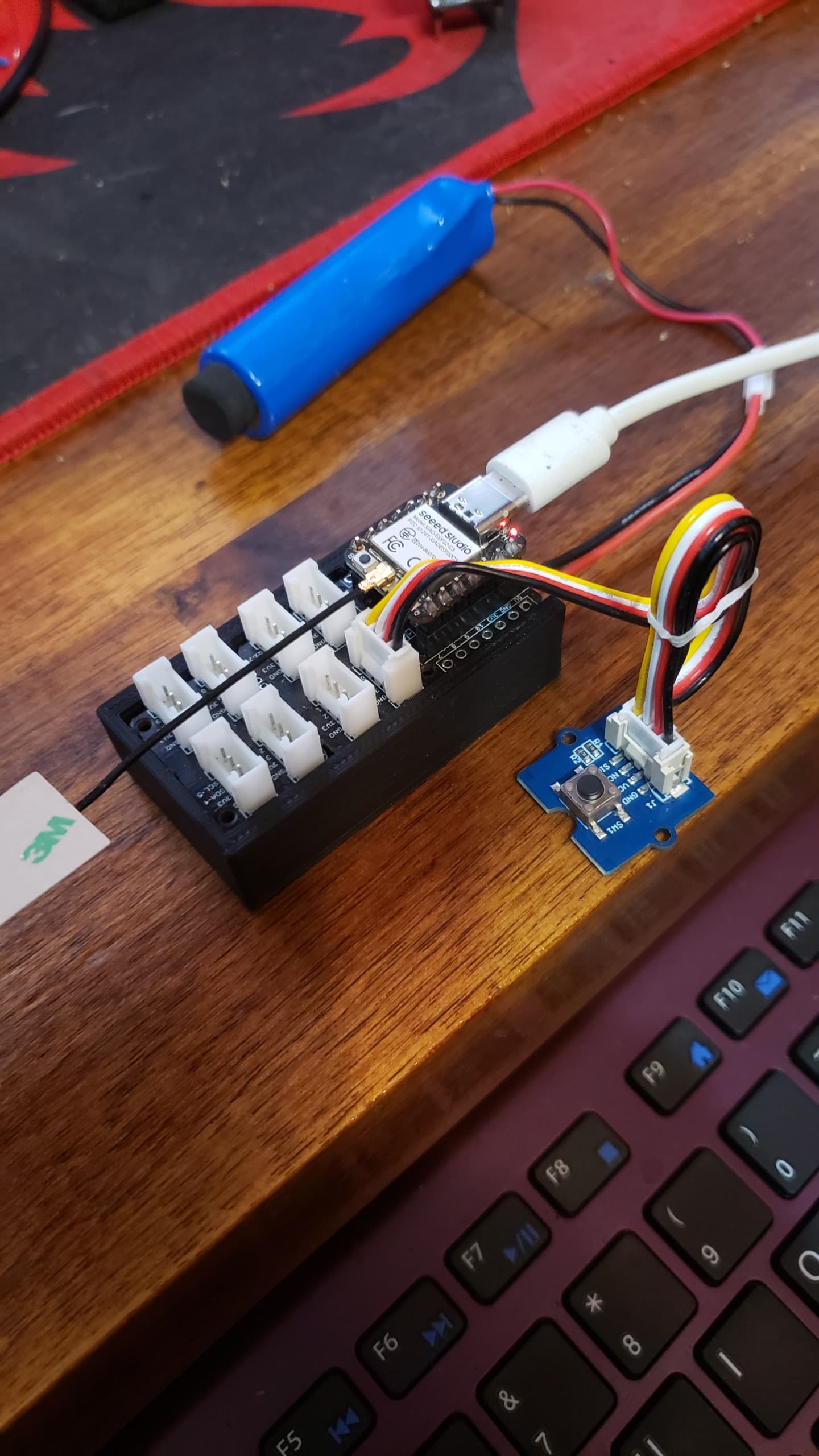
The RTC module is pretty standard: DS3231 AT24C32 Real Time Clock Module.
I am not sure if there is a pullup resistor on it already.
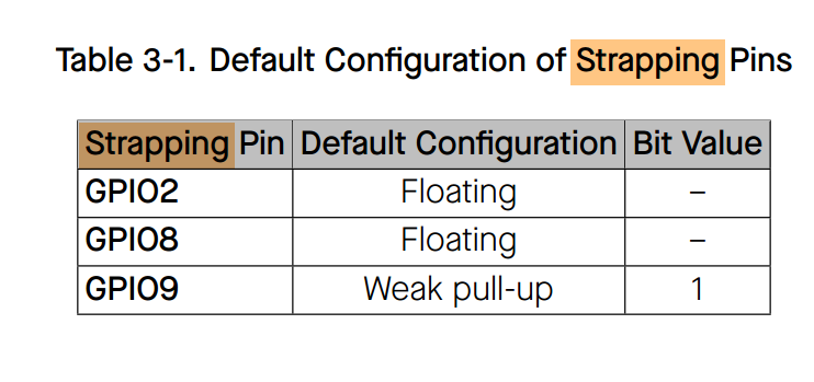
The boot resets I got also seems to be related to my failed attempt at getting this to work, as I get the same issue when I change to D1 as rtc pin.
The RTC module has worked as expected with alarms not involving deep sleep.
TBH, your keypad example is a bit too complex for me to decipher the parts I could use. I can share my failed attempt and maybe you can give me some hints based on that?


#include <RTClib.h>


// Define the DS3231 Interrupt pin (will wake-up the ESP32 - must be an RTC GPIO)
#define CLOCK_INTERRUPT_PIN              GPIO_NUM_2  // Only RTC IO are allowed

#define BUTTON_PIN_BITMASK(GPIO) (1ULL << GPIO)  // 2 ^ GPIO_NUMBER in hexvoid setup()

// LED for visual indication
const int ledPin = 10;

// Save how many times the ESP32 woke-up
RTC_DATA_ATTR int bootCount = 0;

// Instance for the RTC
RTC_DS3231 rtc;

// Set the alarm
//DateTime alarm1Time = DateTime(2025, 05, 23, 13, 55, 0);

// Method to print the reason by which ESP32 has been awaken from sleep
void print_wakeup_reason() {
  esp_sleep_wakeup_cause_t wakeup_reason;

  wakeup_reason = esp_sleep_get_wakeup_cause();

  switch (wakeup_reason) {
    case ESP_SLEEP_WAKEUP_EXT0:     Serial.println("Wakeup caused by external signal using RTC_IO"); break;
    case ESP_SLEEP_WAKEUP_EXT1:     Serial.println("Wakeup caused by external signal using RTC_CNTL"); break;
    case ESP_SLEEP_WAKEUP_TIMER:    Serial.println("Wakeup caused by timer"); break;
    case ESP_SLEEP_WAKEUP_TOUCHPAD: Serial.println("Wakeup caused by touchpad"); break;
    case ESP_SLEEP_WAKEUP_ULP:      Serial.println("Wakeup caused by ULP program"); break;
    default:                        Serial.printf("Wakeup was not caused by deep sleep: %d\n", wakeup_reason); break;
  }
}

void IRAM_ATTR onAlarm(){
  Serial.print("Alarm occurred!");
}

void setup() {
  Serial.begin(115200);
 //pinMode(CLOCK_INTERRUPT_PIN,  INPUT);
  
  //Print the wakeup reason for ESP32
  print_wakeup_reason();
  delay(2000);
Serial.println("wakey wakey");
  //Blink the LED when the ESP32 wakes-up
  digitalWrite(ledPin, HIGH);
  delay(1000);
  digitalWrite(ledPin, LOW);

  // Initialize the RTC
  if(!rtc.begin()) {
    Serial.println("Couldn't find RTC!");
    Serial.flush();
    while (1) delay(10);
  }

  // We don't need the 32K Pin, so disable it
  rtc.disable32K();

  // The alarm will trigger an interrupt
  pinMode(CLOCK_INTERRUPT_PIN, INPUT_PULLUP);
  attachInterrupt(digitalPinToInterrupt(CLOCK_INTERRUPT_PIN), onAlarm, FALLING);

  // Set alarm 1, 2 flag to false (so alarm 1, 2 didn't happen so far)
  // if not done, this easily leads to problems, as both register aren't reset on reboot/recompile
  rtc.clearAlarm(1);
  rtc.clearAlarm(2);

  // Stop oscillating signals at SQW Pin otherwise setAlarm1 will fail
  rtc.writeSqwPinMode(DS3231_OFF);

  // Turn off alarm 2 (in case it isn't off already)
  // again, this isn't done at reboot, so a previously set alarm could easily go overlooked
  rtc.disableAlarm(2);
//Serial.println(rtc.now());
  // Schedule an alarm
if(!rtc.setAlarm1(rtc.now() + TimeSpan(0, 0, 2, 0), DS3231_A1_Minute)); 
  
  // Increment boot number and print it every reboot
  ++bootCount;
  Serial.println("Boot number: " + String(bootCount));

  // Configure external wake-up
  //esp_sleep_enable_ext0_wakeup(CLOCK_INTERRUPT_PIN, 0);  //1 = High, 0 = Low
  esp_deep_sleep_enable_gpio_wakeup(BUTTON_PIN_BITMASK(CLOCK_INTERRUPT_PIN),ESP_GPIO_WAKEUP_GPIO_HIGH); 

  Serial.println("Going to sleep now");
  esp_deep_sleep_start();
}

void loop() {
  // The code never reaches the loop, because the ESP32 goes to sleep at the end of setup
  //Serial.print("This will never be printed!");
}

This last version doesn´t crash, but just constantly wakes up:
11:14:12.358 → wakey wakey

11:14:13.381 → Boot number: 2

11:14:13.381 → Going to sleep now

11:14:15.426 → Wakeup was not caused by deep sleep: 7

11:14:15.426 → wakey wakey

11:14:16.712 → Boot number: 3

Here is the code I used. I don’t have a DS3231 so just removed it with the #define USE_RTC.


#define USE_RTC  //!!!GR!!! - I don't have a DS3231 so just removed the code with this define.

#ifdef USE_RTC
#include <RTClib.h>
#endif  // USE_RTC

#include "driver/rtc_io.h"

// Define the DS3231 Interrupt pin (will wake-up the ESP32 - must be an RTC GPIO)
#define CLOCK_INTERRUPT_PIN GPIO_NUM_2  // Only RTC IO are allowed
#define CLOCK_PIN_MASK 1 << CLOCK_INTERRUPT_PIN

// LED for visual indication
const int ledPin = GPIO_NUM_4;

// Save how many times the ESP32 woke-up
RTC_DATA_ATTR int bootCount = 0;

#ifdef USE_RTC
// Instance for the RTC
RTC_DS3231 rtc;

// Set the alarm
DateTime alarm1Time = DateTime(2024, 12, 18, 12, 25, 0);
#endif  // USE_RTC

//!!!GR!!!
bool sleep_permitted = false;

// Method to print the reason by which ESP32 has been awaken from sleep
void print_wakeup_reason() {
  esp_sleep_wakeup_cause_t wakeup_reason;

  wakeup_reason = esp_sleep_get_wakeup_cause();

  switch (wakeup_reason) {
    case ESP_SLEEP_WAKEUP_EXT0:
      Serial.println("Wakeup caused by external signal using RTC_IO");
      break;
    case ESP_SLEEP_WAKEUP_EXT1:
      Serial.println("Wakeup caused by external signal using RTC_CNTL");
      break;
    case ESP_SLEEP_WAKEUP_TIMER:
      Serial.println("Wakeup caused by timer");
      break;
    case ESP_SLEEP_WAKEUP_TOUCHPAD:
      Serial.println("Wakeup caused by touchpad");
      break;
    case ESP_SLEEP_WAKEUP_ULP:
      Serial.println("Wakeup caused by ULP program");
      break;
    default:
      Serial.printf("Wakeup was not caused by deep sleep: %d\r\n", wakeup_reason);
      break;
  }
}

void IRAM_ATTR onAlarm() {
  Serial.println("Alarm occurred!");
}

void setup() {
  Serial.begin(115200);
  delay(2000);

  pinMode(ledPin, OUTPUT);

  //Print the wakeup reason for ESP32
  print_wakeup_reason();

  // Blink the LED when the ESP32 wakes-up
  digitalWrite(ledPin, HIGH);
  delay(1000);
  digitalWrite(ledPin, LOW);

#ifdef USE_RTC
  // Initialize the RTC
  if (!rtc.begin()) {
    Serial.println("Couldn't find RTC!");
    Serial.flush();
    while (1) delay(10);
  }

  if (rtc.lostPower()) {
    // this will adjust to the date and time at compilation
    rtc.adjust(DateTime(F(__DATE__), F(__TIME__)));
  }

  // Uncomment if you need to define the time of the RTC
  //rtc.adjust(DateTime(F(__DATE__), F(__TIME__)));

  // We don't need the 32K Pin, so disable it
  rtc.disable32K();
#endif  // USE_RTC

  // The alarm will trigger an interrupt
  pinMode(CLOCK_INTERRUPT_PIN, INPUT_PULLUP);
  attachInterrupt(CLOCK_INTERRUPT_PIN, onAlarm, FALLING);

  //!!!GR!!!
  if (esp_deep_sleep_enable_gpio_wakeup(CLOCK_PIN_MASK, ESP_GPIO_WAKEUP_GPIO_LOW) == ESP_OK) {
    Serial.println("Clock Mask : 0x" + String(CLOCK_PIN_MASK, HEX));
    sleep_permitted = true;
  } else {
    Serial.println("Clock Wake Error");
    sleep_permitted = false;
  }

#ifdef USE_RTC
  // Set alarm 1, 2 flag to false (so alarm 1, 2 didn't happen so far)
  // if not done, this easily leads to problems, as both register aren't reset on reboot/recompile
  rtc.clearAlarm(1);
  rtc.clearAlarm(2);

  // Stop oscillating signals at SQW Pin otherwise setAlarm1 will fail
  rtc.writeSqwPinMode(DS3231_OFF);

  // Turn off alarm 2 (in case it isn't off already)
  // again, this isn't done at reboot, so a previously set alarm could easily go overlooked
  rtc.disableAlarm(2);

  // Schedule an alarm
  if (!rtc.setAlarm1(alarm1Time, DS3231_A1_Minute)) {  // this mode triggers the alarm when the minutes match
    Serial.println("Error, alarm wasn't set!");
  } else {
    Serial.println("Alarm will happen at specified time");
  }
#endif  // USE_RTC

  // Increment boot number and print it every reboot
  ++bootCount;
  Serial.println("Boot number: " + String(bootCount));

  // Configure external wake-up
  //!!!GR!!! esp_sleep_enable_ext0_wakeup(CLOCK_INTERRUPT_PIN, 0);  //1 = High, 0 = Low
  // Configure pullup/downs via RTCIO to tie wakeup pins to inactive level during deepsleep.
  // The RTC SQW pin is active low
  //!!!GR!!! rtc_gpio_pulldown_dis(CLOCK_INTERRUPT_PIN);
  //!!!GR!!! rtc_gpio_pullup_en(CLOCK_INTERRUPT_PIN);

  delay(5000);
  if (sleep_permitted) {
    //Go to sleep now until an alarm fires
    Serial.println("Going to sleep in 1 second");
    delay(1000);
    esp_deep_sleep_start();
  }
}

void loop() {
  delay(5000);
  // The code never reaches the loop, because the ESP32 goes to sleep at the end of setup
  Serial.println("This will never be printed!");
}

I also add some extra timeouts.

1 Like

I really appreciate this, thank you :grinning:
It seems to work fine on D0 without a pullup resistor, so hopefully this means there is one built into the RTC module. I modified it so it now wakes up every minute, and I will keep it running through the day to check if there are any mistriggers.
The xiao esp32c3 is a tricky little fellow, but I am happy to have discovered this forum with knowledgable people!

2 Likes