Hi Everyone,
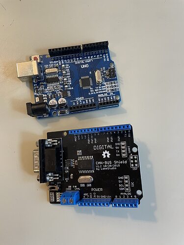
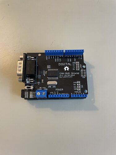
I am new to arduino and I bought a Seed Studio CAN-BUS Shield V1.2 the other day.
I am trying to make a speedometer for a 2008 Mazda 3. I downloaded the Seed library and tried the example sketch “recive_check.ino” with every default baud rate but to no avail. Any help would be appreciated.
also this device is an upgrade for XIAO
Maybe you can find some information in here
Hi there,
I already tried reading that wiki but it didnt help (thats where i found out to try the different baud rates).
also i dont want to buy more stuff if possible and I am using an arduino so that I have more pin outs for extra modules.
Hi there,
can you post a picture of how you have this setup?
GL ![]() PJ
PJ
![]()
yes… i was just providing information… you may look at the new code for information… as PJ said probably a wiring issue
Hi there,
When you power it on , Does it flash ? How many times, the LED?
GL ![]() PJ
PJ
![]()
Two leds power on, they dont flash. PWR1 turns on when the board is poered by smth like the computer i am attempting to code it with or when it is plugged into the obd port which also has a power source. The other led is the rx1 and it turns on when the car is on, the board plugged into the port, the code is running and the board is receiving info.
how do i share pictures
Hi there,
Use the disc with up arrow on it next to the code tags </> to the left.
HTH
GL ![]() PJ
PJ ![]()
it says that i cant share media
Yea, making sure your not a bot … LOL
need a few posts or something.
GL ![]() PJ
PJ ![]()
Hi there,
Yea , those are the “Clone Shields” by LSeeStudio ? , Pretty good hardware. AFAIK.
Should do all the basics and a few of the advanced things too!
they also offer a listener / Receive only device too. $24 little high but it’s usb to the laptop.
fyi.
So you mount it on the UNO and what is the basic sketch and are you plugging into the H & L ?
GL ![]() PJ
PJ ![]()
you started wit receive check ino, ok.
I ordered one of the Can bus Xiao adapters.

// demo: CAN-BUS Shield, receive data with check mode
// send data coming to fast, such as less than 10ms, you can use this way
// loovee, 2014-6-13
#include <SPI.h>

#define CAN_2515
// #define CAN_2518FD

// Set SPI CS Pin according to your hardware

#if defined(SEEED_WIO_TERMINAL) && defined(CAN_2518FD)
// For Wio Terminal w/ MCP2518FD RPi Hat:
// Channel 0 SPI_CS Pin: BCM 8
// Channel 1 SPI_CS Pin: BCM 7
// Interupt Pin: BCM25
const int SPI_CS_PIN  = BCM8;
const int CAN_INT_PIN = BCM25;
#else

// For Arduino MCP2515 Hat:
// the cs pin of the version after v1.1 is default to D9
// v0.9b and v1.0 is default D10
const int SPI_CS_PIN = 9;
const int CAN_INT_PIN = 2;
#endif


#ifdef CAN_2518FD
#include "mcp2518fd_can.h"
mcp2518fd CAN(SPI_CS_PIN); // Set CS pin
#endif

#ifdef CAN_2515
#include "mcp2515_can.h"
mcp2515_can CAN(SPI_CS_PIN); // Set CS pin
#endif

void setup() {
    SERIAL_PORT_MONITOR.begin(115200);

    while (CAN_OK != CAN.begin(CAN_1000KBPS)) {             // init can bus : baudrate = 500k
        SERIAL_PORT_MONITOR.println("CAN init fail, retry...");
        delay(100);
    }
    SERIAL_PORT_MONITOR.println("CAN init ok!");
}


void loop() {
    unsigned char len = 0;
    unsigned char buf[8];

    if (CAN_MSGAVAIL == CAN.checkReceive()) {         // check if data coming
        CAN.readMsgBuf(&len, buf);    // read data,  len: data length, buf: data buf

        unsigned long canId = CAN.getCanId();

        SERIAL_PORT_MONITOR.println("-----------------------------");
        SERIAL_PORT_MONITOR.print("Get data from ID: 0x");
        SERIAL_PORT_MONITOR.println(canId, HEX);

        for (int i = 0; i < len; i++) { // print the data
            SERIAL_PORT_MONITOR.print(buf[i], HEX);
            SERIAL_PORT_MONITOR.print("\t");
        }
        SERIAL_PORT_MONITOR.println();
    }
}

/*********************************************************************************************************
    END FILE
*********************************************************************************************************/
theres a bunch of extra stuff idk what the purpose is of. Also everone mentions those xiao can bus adapters. how does that work? do i just take three of the obd wires and plug them in?
Hi there,
You have the same and more on the shield.
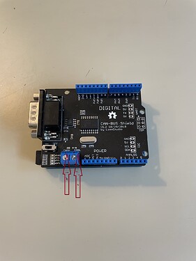
Just the H & L are required to get stuff.
the wiki has links to cables and adapters etc.
You need to set the correct CS pin for the version you have.
slow everything down too, 500k on can bus to start , get it working then turn it up.
Also set the serial port to 9600, add a startup prompt and delay to see when it working.
HTH
GL ![]() PJ
PJ
![]()
so i need to re solder the back smd pad?
also i went through all of the bus baud rates as mentioned in the first post.
also what are you reerring to when you say h&l?
yea. and also, im using the vga adapter. I have a OBD-II to vga cord, not the screw terminals
what do you mean by that?


