Hi everyone,
I’m working on a custom mechanical keyboard built around the Seeed XIAO BLE (nRF52840). It’s Bluetooth-only, so the board carries its own LiPo battery, and I wanted to share (and get feedback on) a design decision I just made: bypassing the XIAO’s onboard charge circuit in favor of an external charging IC.
The XIAO BLE’s built-in charger is great for small, coin-cell-sized batteries, but it only offers two fixed charge-current presets (50 mA or 100 mA) with no way to go higher. I’m sizing my pack in the 1500-2000 mAh range. At 100 mA that’s a 15–20 hour charge from empty, which is way too long for me.
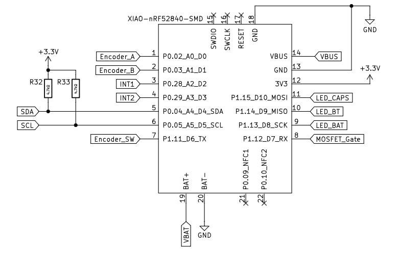
So I added a dedicated Microchip MCP73831-2-OT linear Li-Ion/LiPo charge IC on the PCB, wired independently of the XIAO’s own charge circuitry. It is connected to an extra power-only USB-C port and charges with roughly 500 mA. I attached screenshots of the schematic.
What do you think about this idea? Do you think, this could work? Do you have tips or suggestions for a better design or what do I have to keep in mind?
Tanks in advance for your feedback and thoughts! 
Hi there,
And Welcome here…
So, Hmm. “Thoughts” Ah’  short answer ,
Don’t Do-it" 
I see some things first blush… its going to get HOT!
it or Xiao does not like to get HOT.
Over-lay your design on the Xiao PDF schematic, you will see some parallel power paths that could lead to a problem.
Based on your schematic, LLM see’s these finer points.
Backfeeding the XIAO’s Onboard Battery Pads
-
When charging the 1500–2000 mAh pack at 500 mA using the external MCP73831, the battery voltage terminal will be held at up to 4.2V. 

-
Because the XIAO nRF52840’s bottom battery pads (BAT+ / BAT-) connect directly to its internal charge management circuit (BQ25120), applying an externally driven 4.2V while the XIAO is powered via USB or sleeping can cause backfeeding into the XIAO’s internal PMIC.
-
Risk: The BQ25120 internal PMIC on the XIAO may attempt to regulate or manage an already-driven rail, leading to unexpected current draw, thermal buildup, or logic state confusion.
Thermal Dissipation (Linear Charger Heat)
-
The MCP73831 is a linear charger (SOT-23 package).
-
Dissipating 500mA linear charging current creates significant thermal dissipation:
Power Dissipation = (V_USB - V_BAT) x I_CHG
-
A SOT-23 package without substantial PCB copper heatsinking will run extremely hot (approx 100C+ junction rise), potentially thermal-throttling or causing board warping inside a tight mechanical keyboard enclosure.
Power Path Management & System Load
-
Without an active Power Path circuit (load sharing), the MCP73831 directly powers both the battery and the XIAO simultaneously.
-
If the nRF52840 draws power while charging, the MCP73831 can get tricked into never terminating the charge cycle because the current drop below the termination threshold (ITERM) is never reached.
Suggested Improvements
-
Isolation Diode / MOSFET Isolation:
- Place a low-Vf Schottky diode or a PMOS switch between the external charger output and the XIAO battery pin to isolate the internal PMIC during fast-charging.
-
Upgrade to a Switching Charger:
- Replace the linear MCP73831 with a buck-switching charger IC (like the ETA6002 or TP4056 with proper heatsinking / MAX77654) to eliminate excess heat dissipation when running at 500mA.
-
Implement Proper Load Sharing (Power-Path Control):
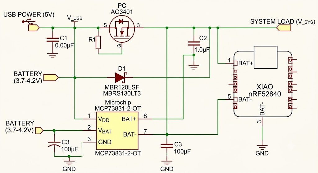
- Use a standard P-Channel MOSFET + Schottky diode circuit between USB power, the battery, and the system load so the keyboard runs directly off USB power while charging, allowing the MCP73831 to terminate properly.
Here is a schematic to consider…more or less of the exercise
OR
DON’t do any of it…
Have you been paying attention?
Here , is your Solution…
HTH
GL PJ 
Thanks a lot for taking the time to dig into this, really appreciate the breakdown!
The backfeeding point is the one that stuck with me most, so I dug into it a bit more. As far as I can tell, the internal charger only ever activates when VBUS sees voltage - it’s dormant otherwise, even with BAT+/BAT- connected to a battery. In my current schematic, the XIAO’s VBUS pin happens to sit on the same net as my external USB-C input, which is exactly what wakes it up and creates the parallel charging path you flagged.
So instead of adding isolation diodes/MOSFETs, I’m thinking of just leaving the XIAO’s VBUS pin unconnected entirely. I don’t need its native USB port anyway (SWD is already broken out separately for flashing), so the internal charger would never see input power and should stay permanently dormant, while BAT+/BAT- keeps doing its normal job of feeding the battery into the board’s power path. That would remove the parallel-charger path without adding extra components.
Does that address the core of what you were worried about, or is there a failure mode I’m not seeing? I’m also planning to beef up the copper pour under the MCP73831 for the thermal concern, and might back the PROG resistor off from 500 mA to something like 350 mA for extra margin.
Would love to hear if this closes the gap, because I really want to get this to work!