Hi!!! It is quite complex what I am doing but probably you can help me.
I am using Stalker V2.3 and GRPRBee
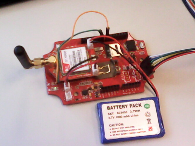
GPRSBee is connected in Bee port but I changed RX and TX pins to be on Stalker Pins 7 and 8. Pic attached
I am running a code where I put the device in sleep mode and wake it up with Real Time Clock every 2 minutes. (Int jumper and PD5 power bee jumper welded in Stalker)
When I wake it up I send through GPRS temperature to Ubidots. I am having some problems with serial communication and connecting to Ubidots.
I guess that there is a problem between libraries SoftwareSerial and Wire.
Thank you very much in advance.
Best,
Rodri
Code based on StalkerV21_DataLogger_5Min.pde but without using SD:
#include <avr/sleep.h>
#include <avr/power.h>
#include <Wire.h>
#include <DS3231.h>
#include <SoftwareSerial.h>
#include <String.h>
SoftwareSerial mySerial(7,8);
//The following code is taken from sleep.h as Arduino Software v22 (avrgcc), in w32 does not have the latest sleep.h file
#define sleep_bod_disable()
{
uint8_t tempreg;
asm volatile(“in %[tempreg], %[mcucr]” “\n\t”
“ori %[tempreg], %[bods_bodse]” “\n\t”
“out %[mcucr], %[tempreg]” “\n\t”
“andi %[tempreg], %[not_bodse]” “\n\t”
“out %[mcucr], %[tempreg]”
: [tempreg] “=&d” (tempreg)
: [mcucr] “I” _SFR_IO_ADDR(MCUCR),
[bods_bodse] “i” (_BV(BODS) | _BV(BODSE)),
[not_bodse] “i” (~_BV(BODSE)));
}
//-------------------------------------------------------------
//---------------------Ubidots Configuration-------------------
//-------------------------------------------------------------
String token = “YRWsXoUOptheqaDFN2T58o65hyHe4m”; //your token to post a value
String idvariable = “5408256b76254210e3acafbf”;
int slpng = 120;
DS3231 RTC; //Create RTC object for DS3231 RTC come Temp Sensor
char weekDay[4] = {“Sun”, “Mon”, “Tue”, “Wed”, “Thu”, “Fri”, “Sat” };
//year, month, date, hour, min, sec and week-day(starts from 0 and goes to 6)
//writing any non-existent time-data may interfere with normal operation of the RTC.
//Take care of week-day also.
DateTime dt(2014, 06, 05, 11, 5, 00, 4);
char CH_status_print[4]= { “Off”,"On ","Ok ",“Err” };
static uint8_t prevSecond=0;
static uint8_t prevMinute=0;
static DateTime interruptTime;
void setup ()
{
pinMode(5,OUTPUT);//extern power xbee
digitalWrite(5, HIGH);
/*Initialize INT0 pin for accepting interrupts */
 PORTD |= 0x04;
 DDRD &=~ 0x04;
 pinMode(4,INPUT);//extern power

 Wire.begin();
 Serial.begin(19200);
 RTC.begin();
 RTC.adjust(dt); //Adjust date-time as defined 'dt' above
 delay(1000);
 attachInterrupt(0, INT0_ISR, LOW); //Only LOW level interrupt can wake up from PWR_DOWN
 set_sleep_mode(SLEEP_MODE_PWR_DOWN);

 //Enable Interrupt
 DateTime start = RTC.now();
 interruptTime = DateTime(start.get() + slpng); //Add 5 mins in seconds to start time
 analogReference(INTERNAL); //Read battery status
 mySerial.begin(19200);
 //digitalWrite(5, LOW);
}
void loop ()
{
//Battery Charge Status and Voltage reader
int BatteryValue = analogRead(A7);
float voltage=BatteryValue * (1.1 / 1024)* (10+2)/2; //Voltage devider
unsigned char CHstatus = read_charge_status();//read the charge status
////////////////////// START : Application or data logging code//////////////////////////////////
RTC.convertTemperature();          //convert current temperature into registers
float temp = RTC.getTemperature(); //Read temperature sensor value

// Convert temperature voltage to string for Ubidots
char buffer5[14]; //make buffer large enough for 7 digits
String temperatureS = dtostrf(temp, 7,2,buffer5);
//'7' digits including '-' negative, decimal and white space. '2' decimal places
temperatureS.trim(); //trim whitespace, important so Ubidots will treat it as a number

DateTime now = RTC.now(); //get the current date-time
if((now.minute()) !=  prevMinute )
{
  //print only when there is a change
  Serial.print(now.year(), DEC);
  Serial.print('/');
  Serial.print(now.month(), DEC);
  Serial.print('/');
  Serial.print(now.date(), DEC);
  Serial.print(' ');
  Serial.print(now.hour(), DEC);
  Serial.print(':');
  Serial.print(now.minute(), DEC);
  Serial.print(':');
  Serial.print(now.second(), DEC);
  Serial.print(" ");
  Serial.print(weekDay[now.dayOfWeek()]);
  Serial.print(" ");
  Serial.print(temp);
  Serial.write(186);
  Serial.print("C, ");
  Serial.print("Battery Voltage -> ");
  Serial.print(voltage);
  Serial.print("V, Charge status --> ");
  Serial.println(CH_status_print[CHstatus]);
}
prevMinute = now.minute();


Serial.print("Sending to Ubidots Temp = "+ temperatureS);
Serial.write(186);
Serial.print("C");
//digitalWrite(5, HIGH);
//delay(2000);
save_value(temperatureS);
//digitalWrite(5, LOW);

RTC.clearINTStatus(); //This function call is  a must to bring /INT pin HIGH after an interrupt.
RTC.enableInterrupts(interruptTime.hour(),interruptTime.minute(),interruptTime.second());    // set the interrupt at (h,m,s)
attachInterrupt(0, INT0_ISR, LOW);  //Enable INT0 interrupt (as ISR disables interrupt). This strategy is required to handle LEVEL triggered interrupt
////////////////////////END : Application code ////////////////////////////////

//\/\/\/\/\/\/\/\/\/\/\/\/Sleep Mode and Power Down routines\/\/\/\/\/\/\/\/\/\/\/\/\/\/\/\

//Power Down routines
cli();
sleep_enable();      // Set sleep enable bit
sleep_bod_disable(); // Disable brown out detection during sleep. Saves more power
sei();

Serial.print("\nSleeping: ");
Serial.print(slpng/60.0);
Serial.println(" minutes");
delay(50); //This delay is required to allow print to complete
//Shut down all peripherals like ADC before sleep. Refer Atmega328 manual
power_all_disable(); //This shuts down ADC, TWI, SPI, Timers and USART
sleep_cpu();         // Sleep the CPU as per the mode set earlier(power down)
sleep_disable();     // Wakes up sleep and clears enable bit. Before this ISR would have executed
power_all_enable();  //This shuts enables ADC, TWI, SPI, Timers and USART
delay(10); //This delay is required to allow CPU to stabilize
Serial.println("Awake from sleep");

//\/\/\/\/\/\/\/\/\/\/\/\/Sleep Mode and Power Saver routines\/\/\/\/\/\/\/\/\/\/\/\/\/\/\/\
}
unsigned char read_charge_status(void)
{
unsigned char CH_Status=0;
unsigned int ADC6=analogRead(6);
if(ADC6>900)
{
CH_Status = 0;//sleeping
}
else if(ADC6>550)
{
CH_Status = 1;//charging
}
else if(ADC6>350)
{
CH_Status = 2;//done
}
else
{
CH_Status = 3;//error
}
return CH_Status;
}
//Interrupt service routine for external interrupt on INT0 pin conntected to DS3231 /INT
void INT0_ISR()
{
detachInterrupt(0);
interruptTime = DateTime(interruptTime.get() + slpng); //decide the time for next interrupt, configure next interrupt
Serial.println(“Interruption”);
}
//this function is to send the sensor data to the Ubidots, you can see the new value in the Ubidots after execute this function
void save_value(String value)
{
//Serial.print(“1”);
int num;
String le;
String var;
var=“{"value":”+ value + “}”;
num=var.length();
le=String(num);
for(int i = 0;i<7;i++)
{
mySerial.println(“AT+CGATT?”); //is connected to GPRS,this is better made repeatedly because it is unstable
delay(2000);
ShowSerialData();
}
//Serial.print(“2”);
mySerial.println(“AT+CSTT=""”); //Set APN //start task and set the APN
delay(2000);
ShowSerialData();
mySerial.println(“AT+CIICR”); //bring up wireless connection with GPRS //bring up wireless connection
delay(3000);
ShowSerialData();
mySerial.println(“AT+CIFSR”); //get local IP address //get local IP adress
delay(2000);
ShowSerialData();
mySerial.println(“AT+CIPSPRT=0”); //no prompt and “send ok” when send successfully
delay(3000);
ShowSerialData();
mySerial.println(“AT+CIPSTART="tcp","","80"”); //start tcp communicatio //start up connection
delay(3000);
ShowSerialData();
mySerial.println(“AT+CIPSEND”); //begin sendiing data to the remote server
delay(5000);
ShowSerialData();
mySerial.print(“POST /api/v1.6/variables/”+idvariable);
delay(100);
ShowSerialData();
mySerial.println(“/values HTTP/1.1”);
delay(100);
ShowSerialData();
mySerial.println(“Content-Type: application/json”);
delay(100);
ShowSerialData();
mySerial.println("Content-Length: "+le);
delay(100);
ShowSerialData();
mySerial.print("X-Auth-Token: ");
delay(100);
ShowSerialData();
mySerial.println(token);
delay(100);
ShowSerialData();
mySerial.println(“Host:”);
delay(100);
ShowSerialData();
mySerial.println();
delay(100);
ShowSerialData();
mySerial.println(var);
delay(100);
ShowSerialData();
mySerial.println();
delay(100);
ShowSerialData();
mySerial.println((char)26);
delay(7000);
mySerial.println();
ShowSerialData();
mySerial.println(“AT+CIPCLOSE”); //close communication
delay(1000);
ShowSerialData();
//Serial.println(“3”);
mySerial.println(“AT+CSCLK=2”); //auto-sleep
}
void ShowSerialData()
{
//Serial.print(“4”);
while(mySerial.available()!=0)
Serial.write(mySerial.read());
}
