Hi there,
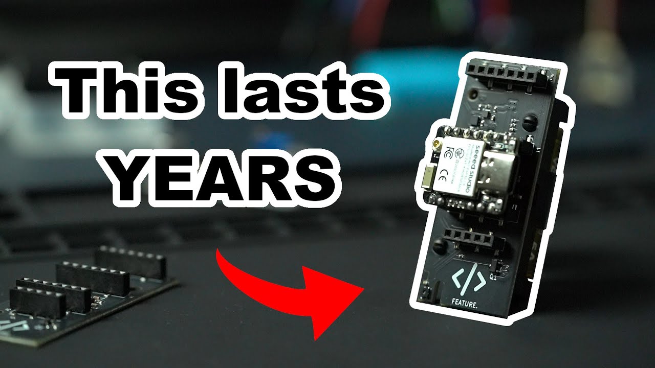
This is the reason , We should ALWAYS have a PMIC on the Xiao,
See he adds all kinds of extra stuff the PMIC would do. Also he could use the nRF54LM20A and save all the battery and MOSFET malarky.
He should have visited the forum for some direction and Time saving information.
LOL, Swap a esp32 for a nRF part…LOL
This is a mess of a video and experience.
I’m sure he learned a lot but seemed too much for him.
Good ,look into NOT what to do when designing an IOT anything.
GL  PJ

Hi There,
So , Incase anyone wants to REALLY do this…
I would do it this way, more current and modern too.
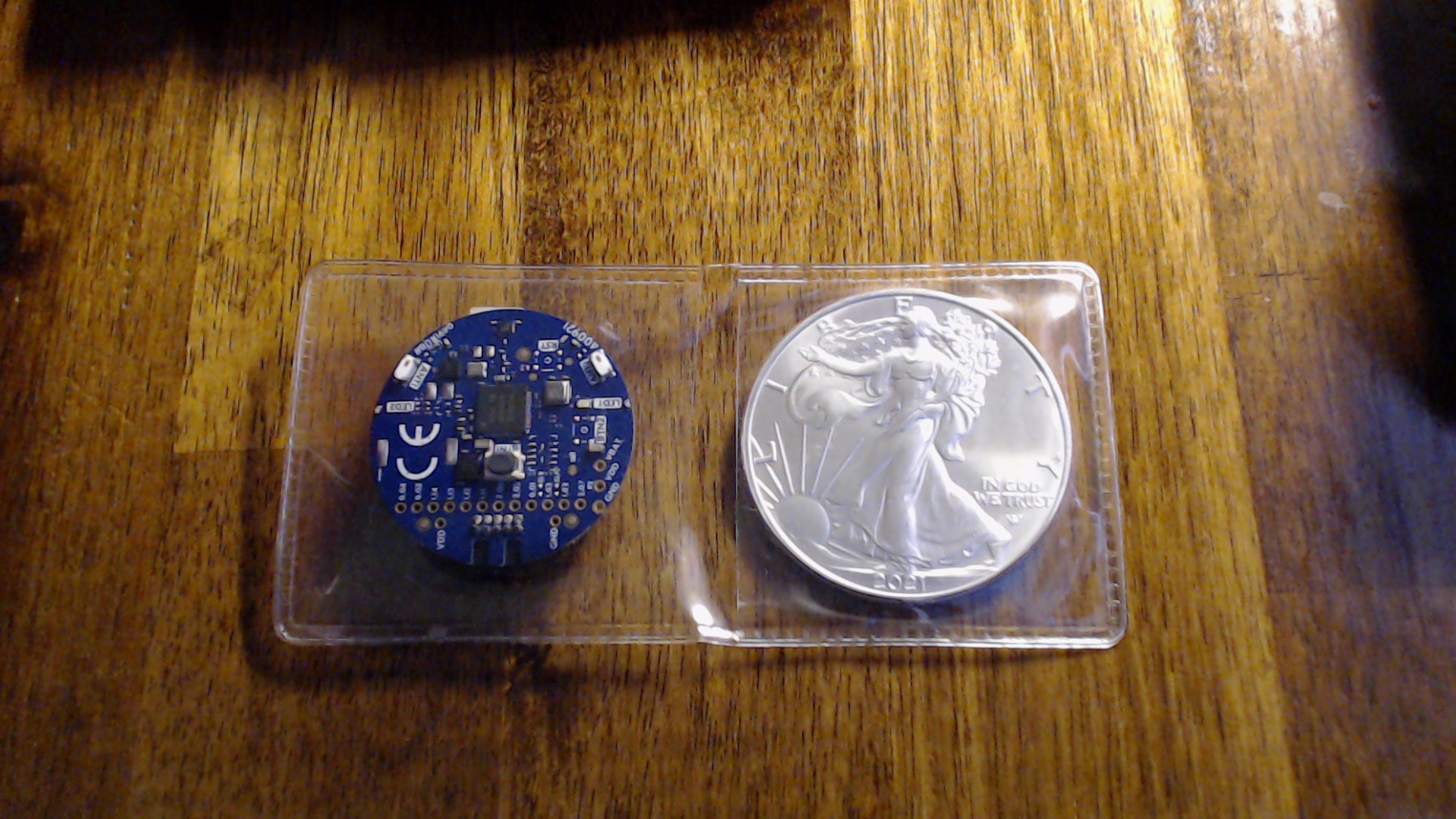
use the nRf54L15 TAG device as the base. btw, the battery is included

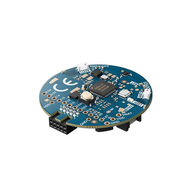
Key Features
-
nRF54L15 SoC in QFN48 package
-
Multi-Protocol Wireless Support:
- Bluetooth® Low Energy
- Matter & Thread®
- 802.15.4 & Zigbee®
- ANT™ & 2.4 GHz proprietary
-
Dual 2.4 GHz Antennas with Bluetooth Channel Sounding support
-
Integrated Sensors:
- Low-power accelerometer
- Inertial Measurement Unit (IMU)
- Environmental sensor
-
User Interface & Expansion:
- User-programmable button & RGB LED
- Expansion footprints for additional buttons, LED, buzzer, and external memory
-
Power & Flashing:
- Integrated CR2032 coin cell battery holder
- Program & debug via nRF54L, nRF53, or nRF91 Series DKs, or SEGGER J-Link
- Over-the-air device firmware update (OTA-DFU) support
Kit Contents
- nRF54L15 Tag hardware with pre-programmed firmware
- CR2032 coin cell battery (included)
- Complete documentation, hardware schematics, and reference layout files

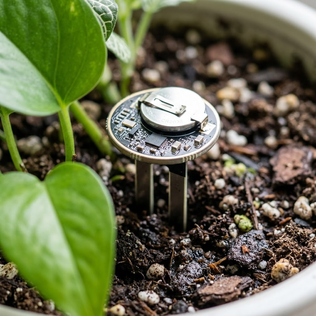
Some Hot Glue and This sensor , and Bob is your Soil Daddy.
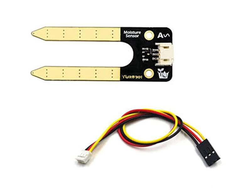
Design & Architecture for a Coin-Sized Form Factor
-
Integrated “Puck-on-Prong” PCB Layout:
-
Instead of wiring a separate probe to a board with cables, the PCB is designed as a single continuous piece: a coin-cell-sized circular head at the top with two parallel capacitive probe traces extending straight down like a fork.
-
The nRF54L15 QFN/WLCSP package, matching passives, and antenna trace sit directly on the top circular pad next to a surface-mount CR2032 (or tiny CR1632) battery clip.
-
-
No External MOSFETs or Power Gating Chips:
-
Standard capacitive soil oscillators draw around 3 mA to 5 mA when active. Because the nRF54L15’s GPIOs support high-drive mode, pin $V_{\text{DD}}$ feeds the probe circuit directly from a single GPIO.
-
Sequence: GPIO goes
HIGH$\rightarrow$ wait 5 ms for oscillation to settle $\rightarrow$ sample via SAADC $\rightarrow$ drive GPIOLOW$\rightarrow$ enter deep sleep (<1 µA).
-
-
Protection & Potting:
-
The bottom capacitive fingers are completely insulated in conformal coating or solder mask so no metal touches the dirt (eliminating oxidation and galvanic corrosion).
-
The top circular head sits just above the soil line and can be sealed in a small 3D-printed cap or dipped in epoxy for full outdoor weatherproofing.
-
You could add more sensor’s to adjacent pots/plants and have multiple channels. per/sensor-head.
-
Homie in the video, way over did it and didn’t make it happen… this will.
HTH
GL PJ
coding this would be a 3rd grader and about a hour ,Tested. definitely NOT rocket Science. 
and you could have them in nRF_Cloud if you so desire… with a dashboard.


 PJ