both have presoldered headera from seeed - esp32s3 sense has male pins and the camera - lora has female with male pins below the board - and yes im trying to use b2b - plugging esp32s3 sense into the lora female connector. I did a multimeter check and 3.3v is reading 3.3v so current is passing through the b2b.

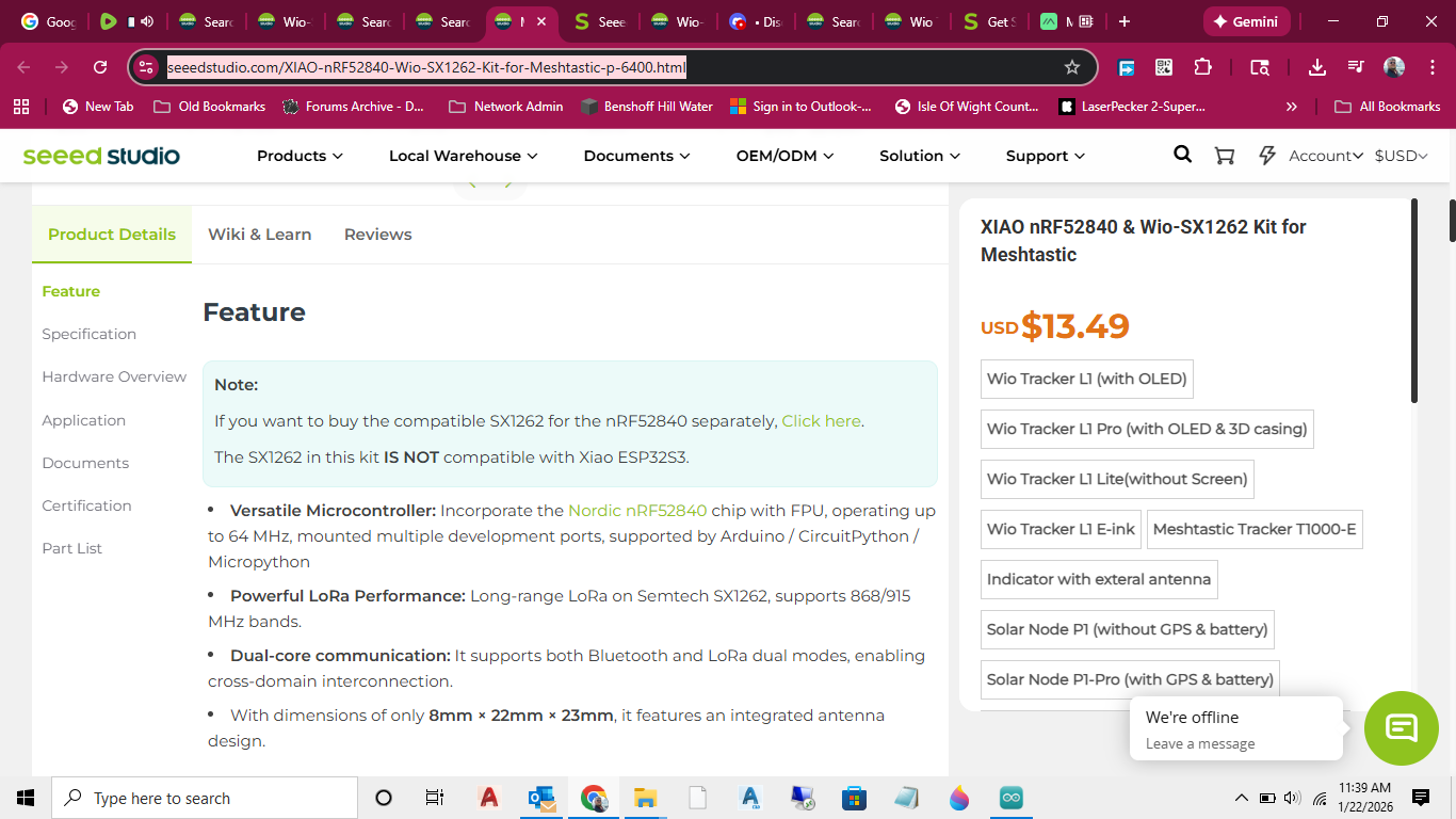
the presoldered wio-sx1262 with female up top and male below is what I am using - or trying to use - I need the camera as the app Im writing is a surveillance system - so a vanilla esp32s3 wasn’t an option - I thought the sense board with this looked like the easiest way to go. So you are saying the board combination is incompatible for some reason? Can you recommend a sure fire lora that works with the esp32s3 sense?
No, you have the wrong code for that board.
GL ![]() PJ
PJ ![]()
now I see why you had theSPI stuff, not needed anyway.
I’ll post the correct version.
Also START with the Camera removed for testing.
just work with the S3 and Lora first.
![]()
it may be possable but you have to understand that the code is absolutly different, because the b2b GPIO pins are completely different than the pin GPIO… so you would have to dig deep into the code to figgure it out… I am pretty sure they should work as you have shown… technically, but the codebase is not set that way
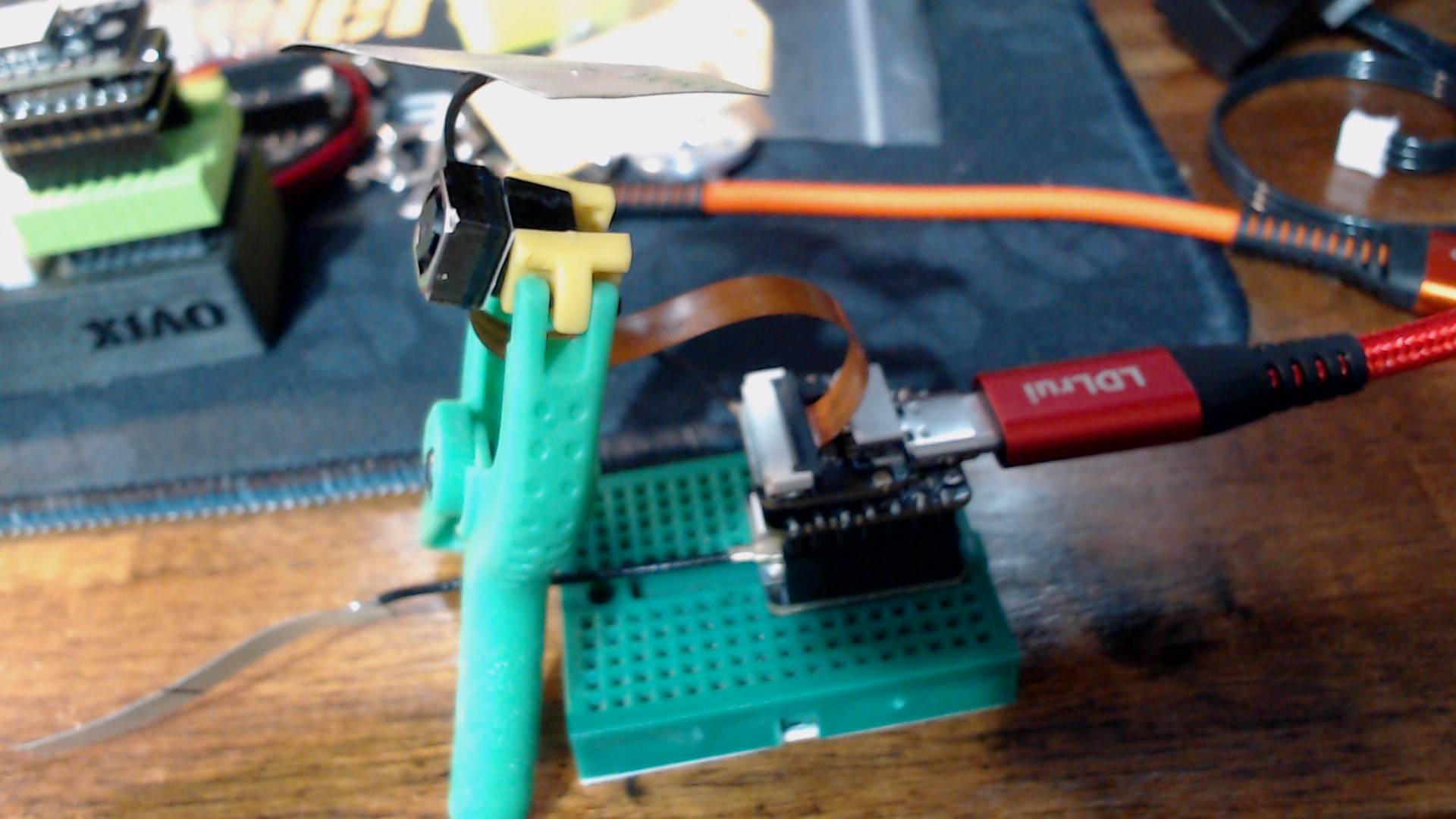
yeah I see you have a usb into your lora - I dont have a usb connector on my lora - thats on the esp32s3 sense -
standing by - my mistake on the code reversal - I didnt think that would be an issue on something like b2b…I thought the spi might be faulty on the esp32 when I started this so I added the checks to see if I had a bad board. Copy on the camera - will remove
Hi there,
Who say’s it doesn’t work ?
It’s an SPI device, it needs the proper configuration is all , electrically ,no reason it wont work Unless the schematic is wrong?
There may be some pin duplication with the B2B maybe is possible But I doubt it.
Some posted the HAllow RF Board sending the Sense camera picture or video feed over that. so the LoRA board would be next , but it’s BW limited so …YMMV
GL ![]() PJ
PJ ![]()
Hi there,
Ah’ I see that fine print , Hmm I’m Suspicious of that. I’ll look at the schematic, I think @msfujino , did something on this.? can’t recall at the moment.
I’ll swap them around and edit the code YOLO is what they say , so there’s That ![]()
![]()
HTH
GL ![]() PJ :v;
PJ :v;
This way ![]()
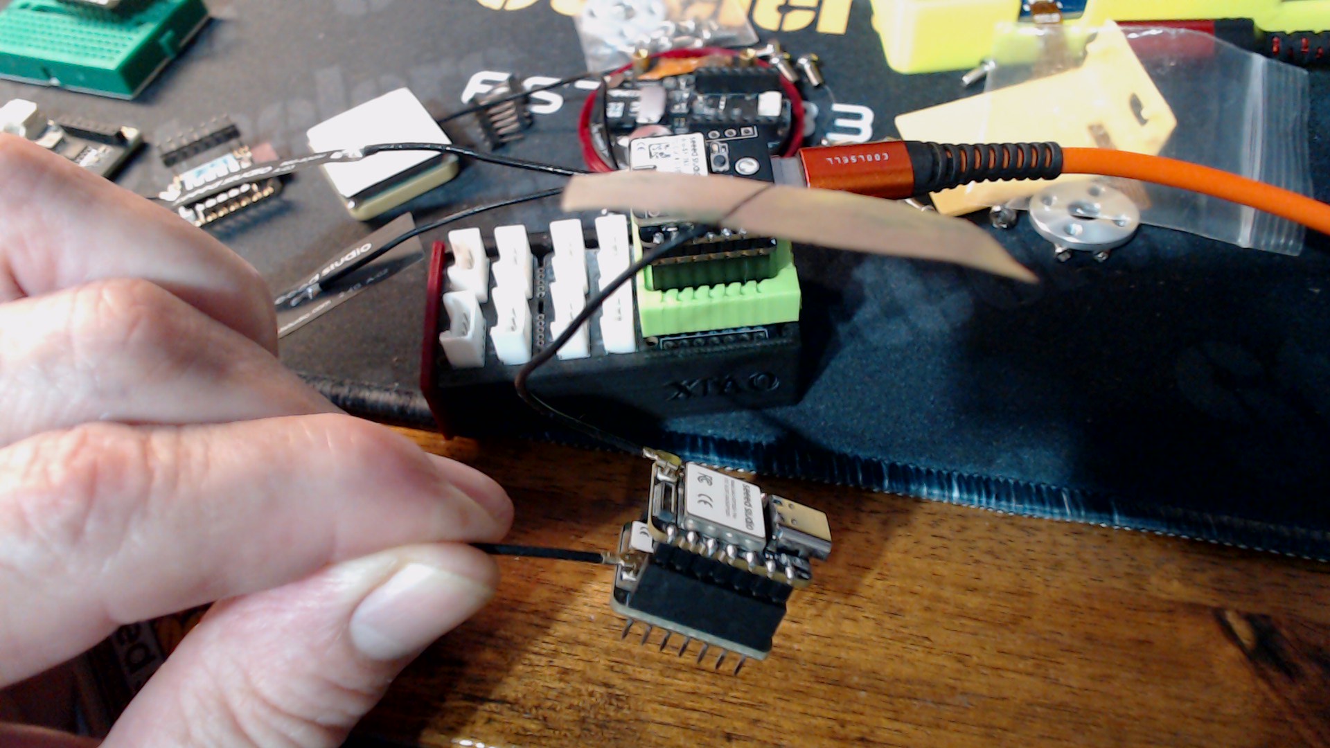
his Usb is going into the XIAO below… he has the Lora -B2B on top to S3 sandwitch in the picture
what you are wanting is the camera sandwitch with the lora on the bottom
PJ will get it in a jiffy

Plus

yes thats my config … esp32s3 sense on top - lora on the bottom with the esp32 male header pins plugged into the lora female socket… I’m constrained in how I stack thanks to what this is going into as its also paired with a microphone vibration sensor and other stuff. I just wanted to get the lora working before I added the other items - those are all pretty simple - just power and the right io pin on the esp. The lora has been my sticking point.
worst case you could get 2 units one for camera and one for lora operations
The only problem i see is the IIC pins 4&5 are being used in this configuration
yes pj thats my stack - Im space constrained to that thanks to other sensors I’m including in a small space - vibration, microphone etc.
with the Lora on the bottom.. all you will have is UART… you will not have IIC or any other pins to work with.. all will be used up… BUT you could check into

BUT these pins are probably some that are used by the B2b connector
Hi there
Yatzy! 
=== Updated RadioLib Test for Wio-SX1262 on XIAO ESP32S3 ===
Pins: NSS=5, DIO1=2, RST=3, BUSY=4, ANT_SW=6
WiFi and Bluetooth disabled
Antenna switch enabled (GPIO38 HIGH)
Setting TCXO voltage to 1.6 V…
Initializing LoRa…
SUCCESS! LoRa initialized fully.
SX1262 chip detected and ready at 915 MHz, SF11, BW125, CR 4/5, Tx 20 dBm
#include <RadioLib.h>
#include <esp_wifi.h> // Required for esp_wifi_stop()
#include <esp_bt.h> // Required for esp_bt_controller_disable()
// B2B pin mapping for Wio-SX1262 on XIAO ESP32S3
#define ANT_SW 6 // Antenna Switch (GPIO38)
// SX1262 Module Pins: NSS, DIO1, RST, BUSY
SX1262 radio = new Module(5, 2, 3, 4);
// -------------------- SX1262 GPIO pins (S3 pins FINAL) --------------------
#define LORA_DIO1   2
#define LORA_RST    3
#define LORA_BUSY   4
#define LORA_CS     5 //NSS
#define LORA_RF_SW1 6

void setup() {
Serial.begin(115200);
delay(2000); // Give serial time to connect
Serial.println("=== Updated RadioLib Test for Wio-SX1262 on XIAO ESP32S3 ===");
Serial.println("Pins: NSS=5, DIO1=2, RST=3, BUSY=4, ANT_SW=6");
// Disable WiFi & Bluetooth to free resources (optional but recommended)
esp_wifi_stop();
esp_bt_controller_disable();
Serial.println("WiFi and Bluetooth disabled");
// Antenna switch - set HIGH to enable RF path (important for SX1262)
pinMode(ANT_SW, OUTPUT);
digitalWrite(ANT_SW, HIGH);
Serial.println("Antenna switch enabled (GPIO38 HIGH)");

// Set TCXO voltage - critical for Wio-SX1262 (try 1.6 first, then 1.8 if fails)

Serial.println("Setting TCXO voltage to 1.6 V…");
radio.setTCXO(1.6);
delay(200);
// Initialize LoRa

Serial.println("Initializing LoRa…");
//int state = radio.begin(915.0, 125.0, 7, 5, 0x12, 8, 17);
/*SF7 is "most compatible"
CR 4/5
Sync word 0x12 (public LoRa)
Preamble 8
TX power 14–17 dBm is safe on most modules*/
// If you want Private uncomment below
int state = radio.begin(915.0, 125.0, 7, 5, RADIOLIB_SX126X_SYNC_WORD_PRIVATE, 8, 17);
// The 200 was the KILLER BTW, wrong Param. :+1:

//int state = radio.begin(915.0, 125.0, 11, 5, RADIOLIB_SX126X_SYNC_WORD_PRIVATE, 20, 200, 0);

if (state == RADIOLIB_ERR_NONE) {
Serial.println("SUCCESS! LoRa initialized fully.");
Serial.println("SX1262 chip detected and ready at 915 MHz, SF11, BW125, CR 4/5, Tx 20 dBm");
} else {

Serial.print("LoRa init FAILED with code: ");

Serial.println(state);

Serial.println("Common codes:");

Serial.println(" -2 = No module detected (B2B contact / hardware)");

Serial.println(" -5 = TCXO calibration failed (try 1.8 V)");

Serial.println(" -3 = SPI communication failure");

Serial.println(" -1 = General error");


// Automatic retry with TCXO 1.8 V

Serial.println("\\nRetrying with TCXO 1.8 V...");

radio.setTCXO(1.8);

delay(200);

state = radio.begin(915.0, 125.0, 11, 5, RADIOLIB_SX126X_SYNC_WORD_PRIVATE, 20, 200, 0);

Serial.print("Retry result: ");

Serial.println(state);

if (state == RADIOLIB_ERR_NONE) {

  Serial.println("SUCCESS on retry! Use TCXO 1.8 V in main code.");

}
}

Serial.println("\n=== Test Complete ===");

}

void loop() {

// Idle - test runs once on boot

delay(10000);

}
GL ![]() PJ
PJ ![]()
You should be able to land-it from here ![]()
![]()
Doesn’t seem to mind it being connected ![]()
Do us a Solid and Mark it as the Solution Please ![]()
wow.. I might have to try this one for myself Good Job
If you would like you can make an excelent forum post with all the details we need to know for future reference
That is a Great Idea , On create a New Thread and Post and link any pertinent info back here .. ![]() Kind of cleans it up Too ! , I like It!
Kind of cleans it up Too ! , I like It!
Add that Fancy GPS ![]()
Then we know where we are … LOL ![]()
GL ![]() PJ
PJ ![]()
also it makes it easier to find in the future… like i did with the grove connector… i started a post to try to explain my thinking and i said i know i have covered this ground before… but how to know where.. i think anyone can create a post in the excelent solutions sub area… but if for some reasion you cant just make the post and i will edit the location… i think what you already did is great… but you may rap it with a bow by summary what you did and what you found out IMO
still doesn’t work for me -
=== Updated RadioLib Test for Wio-SX1262 on XIAO ESP32S3 ===
Pins: NSS=5, DIO1=2, RST=3, BUSY=4, ANT_SW=6
WiFi and Bluetooth disabled
Antenna switch enabled (GPIO38 HIGH)
Setting TCXO voltage to 1.6 V…
Initializing LoRa…
LoRa init FAILED with code: -2
Common codes:
-2 = No module detected (B2B contact / hardware)
-5 = TCXO calibration failed (try 1.8 V)
-3 = SPI communication failure
-1 = General error
\nRetrying with TCXO 1.8 V…
Retry result: -2
=== Test Complete ===