SeeedStudio ESP32S3 Sense

I just got the Seeed Studio XIAO ESP32S3 Sense.

I am trying to upload the Blink example. But whenever I am trying to do it, it says Could not open Com6.

So i tried changing to ESP32S3 Dev Module, it successfully upload but then no LED is blinking.

Also the red LED near the Reset pin is bright at first but then is very dim subsequently. What am I doing wrong?

I had similar problems with an XIAO ESP32C3 and the nRF52840. My windows 10 laptop and Arduino would work for several compiles, then just stop with the XIAO boards. My Arduino board worked flawlessly every time. After trying to figure out when to double tap which reset button, then quickly select the correct USB port again… I finally gave up and went over to circuit python. Lots of people have the USB drive issue and I did not find a solid solution that permanently fixed it. I’m sure there is a solution, I just don’t have the patience to find it. I was not very far along in my project so switching over was not an issue for me.

Realized that I had to pick DFRobot Firebeetle 2 ESP32-S3 it managed to work after I tried uploading the Blink program.

But I am unable to make it work with the Round Display by XIAO.

you need to use XIAO ESP32S3 as your board or all bets are off, you cant just compile random boards and epect them to work, especially when using built-in led because the pin may change and some do not have a built-in led at all… smh

1 Like

Well, with DFRobot Firebeetle it works. Also, with the XIAO_ESP32S3 it works too. No error or anything. Managed to upload my code that I used in SAMD21. Thank you

Hi @mdabdillah @Greasenut

If you use xiao esp32s3, you must choose XIAO_ESP32S3 as your development board. If you encounter the problem of not being able to upload, please follow the Wiki steps to enter bootloader mode. Generally this solution can solve the xiao esp32s3 can’t upload problem

The red light next to the reset is the battery charging indicator.When XIAO ESP32S3 is not connected to the battery, the red light comes on when the Type-C cable is connected and goes off after 30 seconds.

2 Likes

I am using the XIAO ESP32S3 SENSE for image classification. I configured the board as per the requirements. the connection were all fine. however when i try to connect to the camera web server , i get some information like this

ESP-ROM:esp32s3-20210327

Build:Mar 27 2021

rst:0x15 (USB_UART_CHIP_RESET),boot:0xb (SPI_FAST_FLASH_BOOT)

Saved PC:0x4037aeb6

SPIWP:0xee

mode:DIO, clock div:1

load:0x3fce3818,len:0x508

load:0x403c9700,len:0x4

load:0x403c9704,len:0xad0

load:0x403cc700,len:0x29d8

entry 0x403c9880

which means
ESP-ROM:** Indicates the version of the ESP32-S3 ROM (Read-Only Memory).
Build:** Specifies the build date of the firmware, in this case, March 27, 2021.
Reset Cause (rst):** The reset cause is 0x15, indicating a USB_UART_CHIP_RESET.
Boot mode (boot):** The boot mode is 0x8, indicating SPI_FAST_FLASH_BOOT.
Saved PC:** This is the address where the program counter was saved during the last reset.
SPIWP:** SPI write protection status is 0xee.
Mode:** DIO (Dual Input/Output) is the SPI flash mode used during boot.
Clock Divisor:** The clock divisor for the SPI flash is set to 1.
Load Addresses:** These lines show the memory addresses and lengths of various code segments being loaded during the boot process.
.
Why i am not getting connected to the wifi and not able to use the camera . can anyone help please ?

Initially I was not able to connect to Wifi.

A wifi scan was done and I saw the network I want to connect to.

The additional step I included was:

WiFi.mode(WIFI_STA);

This sets the ESP32S3 to connect to an access point. After this, I was able to connect to Wifi and use the camera.

It worked for me now. Thank you!

I’m have a horrid time getting my new seeed esp32s3 sense to work with the seeed 1262 LORA - both are presoldered - the esp refuses to ‘see’ the lora even when I use all the proper b2b header pins. Pins cleaned - modules securely seated - See below. Any ideas? I’ve tried two different lora and both return code -2 errors.

// ========================================================

// Simple LoRa Detection Test for Seeed Wio-SX1262 on XIAO ESP32S3 (B2B)

// Confirms if the SX1262 module is present or not

// ========================================================

#include <RadioLib.h>

// Your exact B2B pins from the main sketch

#define PIN_NSS 41

#define PIN_DIO1 39

#define PIN_RST 42

#define PIN_BUSY 40

// SX1262 instance

SX1262 radio = new Module(PIN_NSS, PIN_DIO1, PIN_RST, PIN_BUSY);

void setup() {

Serial.begin(115200);

delay(5000); // Long delay for USB/serial + power stabilization

Serial.println(“=== SIMPLE LoRa MODULE DETECTION TEST ===”);

Serial.println(“Hardware: XIAO ESP32S3 + Wio-SX1262 via B2B”);

Serial.println(“Pins: NSS=41, DIO1=39, RST=42, BUSY=40”);

Serial.println(“Antenna attached? Boards snapped tight? Pads clean?”);

Serial.println(“Starting detection…”);

// Explicit SPI setup (B2B pins)

SPI.begin(7, 8, 9, PIN_NSS); // SCK=7, MISO=8, MOSI=9, SS=41

delay(500);

// Soft reset

Serial.println(“Performing soft reset…”);

radio.reset();

delay(500);

// Try TCXO 1.6 V first

Serial.println(“Trying TCXO 1.6 V…”);

radio.setTCXO(1.6);

delay(200);

int state = radio.begin(915.0, 125.0, 11, 5, RADIOLIB_SX126X_SYNC_WORD_PRIVATE, 14, 8, 0);

Serial.print("First attempt result: ");

Serial.println(state);

if (state == RADIOLIB_ERR_NONE) {

Serial.println("SUCCESS! SX1262 MODULE DETECTED AND WORKING");

Serial.println("Chip responds correctly → hardware is good");

Serial.println("Use TCXO 1.6V in your main code");

} else {

Serial.println("First attempt failed. Trying TCXO 1.8 V...");


radio.setTCXO(1.8);

delay(500);

radio.reset();

delay(200);


state = radio.begin(915.0, 125.0, 11, 5, RADIOLIB_SX126X_SYNC_WORD_PRIVATE, 14, 8, 0);


Serial.print("Second attempt result: ");

Serial.println(state);


if (state == RADIOLIB_ERR_NONE) {

  Serial.println("SUCCESS! SX1262 MODULE DETECTED on second try");

  Serial.println("Hardware is good → use TCXO 1.8V in main code");

} else {

  Serial.println("BOTH ATTEMPTS FAILED");

  Serial.println("Module not detected (code != 0)");

  Serial.println("This is a hardware problem:");

  Serial.println(" - B2B connector not making full contact (even if tight)");

  Serial.println(" - Faulty Wio-SX1262 module (new hardware can be DOA)");

  Serial.println(" - Power/USB issue (try different cable/port/PC)");

  Serial.println("Next step: contact Seeed support or test with manual wires");

}

}

}

void loop() {

// Idle

}

Hi there,

And Welcome Here…

So , First rest assured it does work. Second could you edit your post and use the code tags above “</>” and paste it in there, You’ll get better help and it makes it easier to read and test. :+1:

Can you post the serial output you get as well? , use a seperate set of code tags.

This link may prove useful also.

HTH
GL :slight_smile: PJ :v:

May just be the BSP you are using. :crossed_fingers:

1 Like

Definatly the GPIO’s are not set correctly… probalbly among other code issues

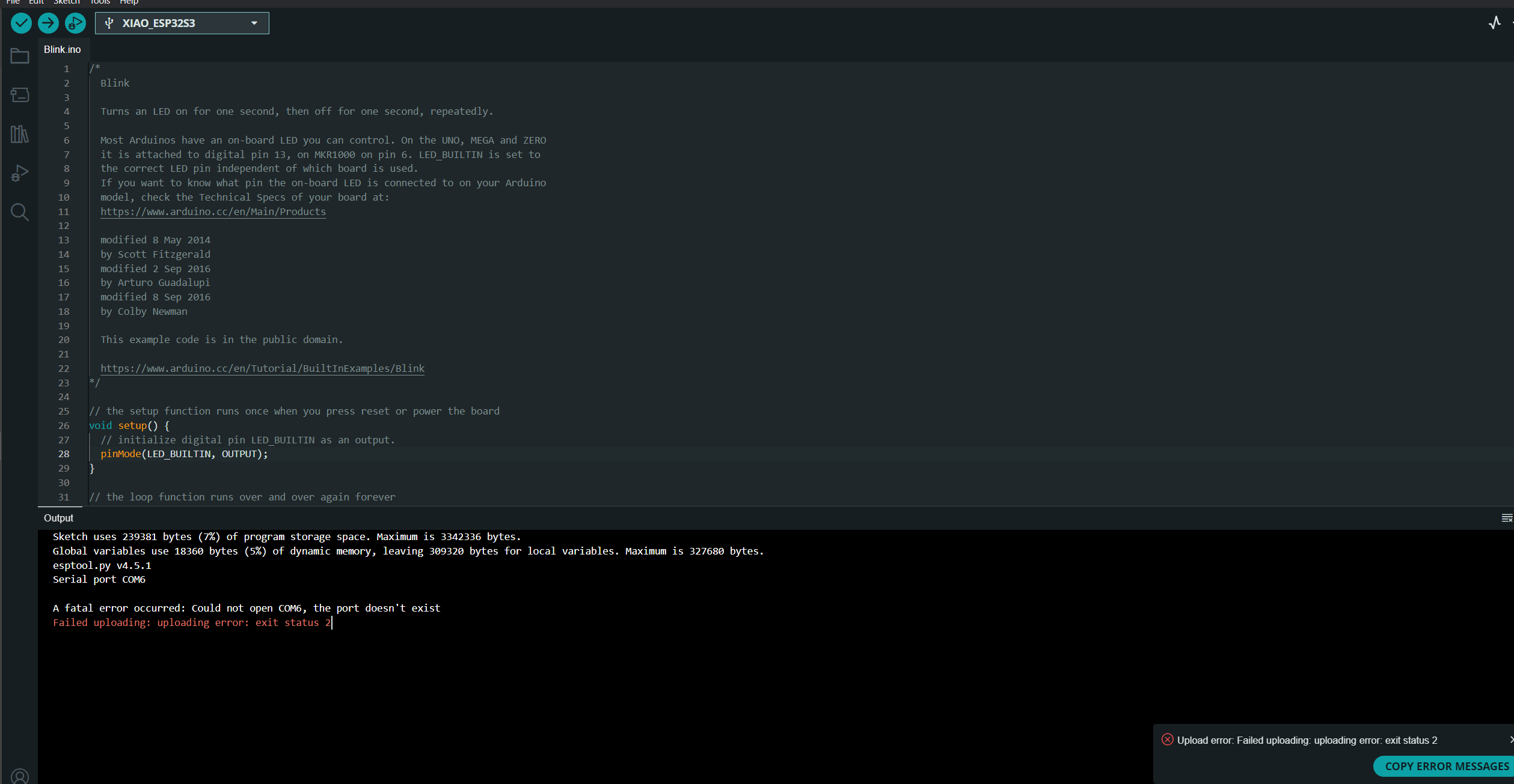
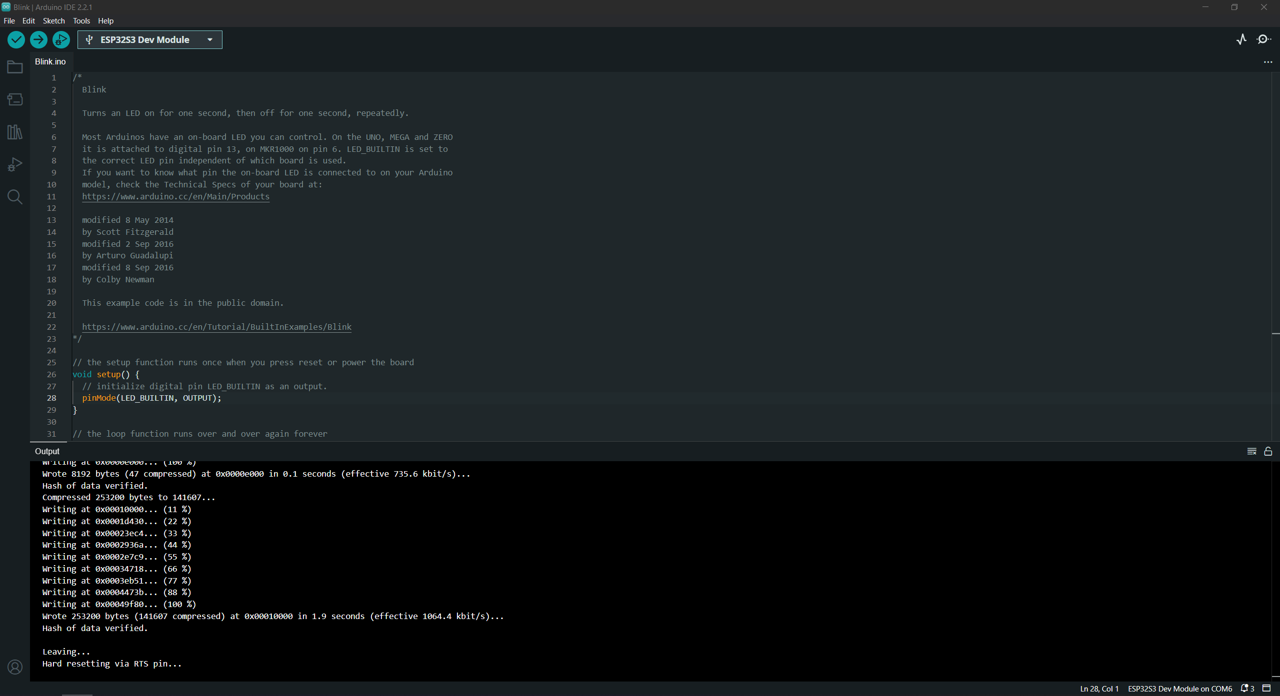
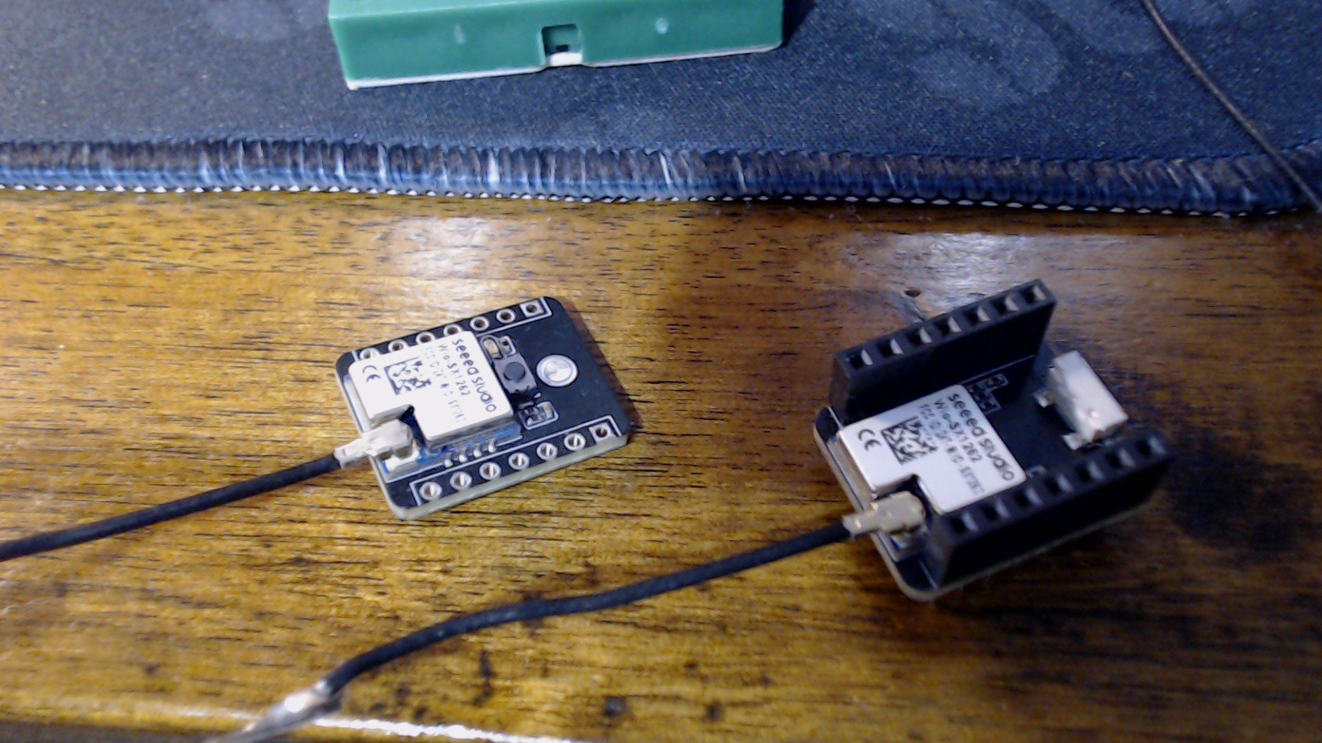
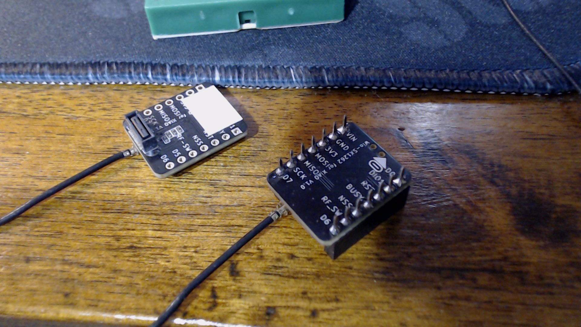
Tried BSP 3.3.3 - no joy - output below - all connected through b2b - nothing other than the esp and lora/antenna with psram enabled for the camera. No its not the pins - definitions are correct as far as I can see…please have a look:

=== Updated RadioLib Test for Wio-SX1262 on XIAO ESP32S3 ===
Pins: NSS=41, DIO1=39, RST=42, BUSY=40, SCK=7, MOSI=9, MISO=8, ANT_SW=38
WiFi and Bluetooth disabled
Antenna switch enabled (GPIO38 HIGH)
Module hardware reset complete
SPI initialized at 4 MHz
Setting TCXO voltage to 1.6 V…
Initializing LoRa…
LoRa init FAILED with code: -2
Common codes:
-2 = No module detected (B2B contact / hardware)
-5 = TCXO calibration failed (try 1.8 V)
-3 = SPI communication failure
-1 = General error

Retrying with TCXO 1.8 V…
Retry result: -2

=== Test Complete ===

code below:

#include <RadioLib.h>

#include <esp_wifi.h> // Required for esp_wifi_stop()

#include <esp_bt.h> // Required for esp_bt_controller_disable()

// B2B pin mapping for Wio-SX1262 on XIAO ESP32S3

#define NSS 41 // SPI Chip Select (GPIO41)

#define SCK 7 // SPI Clock (GPIO7)

#define MOSI 9 // SPI MOSI (GPIO9)

#define MISO 8 // SPI MISO (GPIO8)

#define RST 42 // LoRa Reset (GPIO42)

#define BUSY 40 // LoRa BUSY (GPIO40)

#define DIO1 39 // LoRa IRQ (DIO1 - GPIO39)

#define ANT_SW 38 // Antenna Switch (GPIO38)

// SX1262 instance

SX1262 radio = new Module(NSS, DIO1, RST, BUSY);

void setup() {

Serial.begin(115200);

delay(2000); // Give serial time to connect

Serial.println(“=== Updated RadioLib Test for Wio-SX1262 on XIAO ESP32S3 ===”);

Serial.println(“Pins: NSS=41, DIO1=39, RST=42, BUSY=40, SCK=7, MOSI=9, MISO=8, ANT_SW=38”);

// Disable WiFi & Bluetooth to free resources (optional but recommended)

esp_wifi_stop();

esp_bt_controller_disable();

Serial.println(“WiFi and Bluetooth disabled”);

// Antenna switch - set HIGH to enable RF path (important for SX1262)

pinMode(ANT_SW, OUTPUT);

digitalWrite(ANT_SW, HIGH);

Serial.println(“Antenna switch enabled (GPIO38 HIGH)”);

// Hardware reset the module (important for reliable init)

pinMode(RST, OUTPUT);

digitalWrite(RST, LOW); // Reset active

delay(50); // Hold longer than minimum

digitalWrite(RST, HIGH); // Release

delay(200); // Wait for boot + TCXO startup

Serial.println(“Module hardware reset complete”);

// Explicit SPI init (helps on S3 + B2B setups)

SPI.begin(SCK, MISO, MOSI, NSS);

SPI.setFrequency(4000000); // 4 MHz - safe and reliable

Serial.println(“SPI initialized at 4 MHz”);

// Set TCXO voltage - critical for Wio-SX1262 (try 1.6 first, then 1.8 if fails)

Serial.println(“Setting TCXO voltage to 1.6 V…”);

radio.setTCXO(1.6);

delay(200);

// Initialize LoRa

Serial.println(“Initializing LoRa…”);

int state = radio.begin(915.0, 125.0, 11, 5, RADIOLIB_SX126X_SYNC_WORD_PRIVATE, 20, 200, 0);

if (state == RADIOLIB_ERR_NONE) {

Serial.println("SUCCESS! LoRa initialized fully.");

Serial.println("SX1262 chip detected and ready at 915 MHz, SF11, BW125, CR 4/5, Tx 20 dBm");

} else {

Serial.print("LoRa init FAILED with code: ");

Serial.println(state);

Serial.println("Common codes:");

Serial.println(" -2 = No module detected (B2B contact / hardware)");

Serial.println(" -5 = TCXO calibration failed (try 1.8 V)");

Serial.println(" -3 = SPI communication failure");

Serial.println(" -1 = General error");


// Automatic retry with TCXO 1.8 V

Serial.println("\\nRetrying with TCXO 1.8 V...");

radio.setTCXO(1.8);

delay(200);

state = radio.begin(915.0, 125.0, 11, 5, RADIOLIB_SX126X_SYNC_WORD_PRIVATE, 20, 200, 0);

Serial.print("Retry result: ");

Serial.println(state);

if (state == RADIOLIB_ERR_NONE) {

  Serial.println("SUCCESS on retry! Use TCXO 1.8 V in main code.");

}

}

Serial.println(“\n=== Test Complete ===”);

}

void loop() {

// Idle - test runs once on boot

delay(10000);

}

pins are fine for b2b as far as I can tell

did you say you are using a camera? can you post a picture of your setup?

Hi there,

So you need to use the code tags ABOVE in the edit window PASTE the code there.

#include <RadioLib.h>
#include <esp_wifi.h> // Required for esp_wifi_stop()
#include <esp_bt.h> // Required for esp_bt_controller_disable()
// B2B pin mapping for Wio-SX1262 on XIAO ESP32S3
#define NSS 41 // SPI Chip Select (GPIO41)
#define SCK 7 // SPI Clock (GPIO7)
#define MOSI 9 // SPI MOSI (GPIO9)
#define MISO 8 // SPI MISO (GPIO8)
#define RST 42 // LoRa Reset (GPIO42)
#define BUSY 40 // LoRa BUSY (GPIO40)
#define DIO1 39 // LoRa IRQ (DIO1 - GPIO39)
#define ANT_SW 38 // Antenna Switch (GPIO38)
// SX1262 instance
SX1262 radio = new Module(NSS, DIO1, RST, BUSY);
void setup() {
Serial.begin(115200);
delay(2000); // Give serial time to connect
Serial.println(“=== Updated RadioLib Test for Wio-SX1262 on XIAO ESP32S3 ===”);
Serial.println(“Pins: NSS=41, DIO1=39, RST=42, BUSY=40, SCK=7, MOSI=9, MISO=8, ANT_SW=38”);
// Disable WiFi & Bluetooth to free resources (optional but recommended)
esp_wifi_stop();
esp_bt_controller_disable();
Serial.println(“WiFi and Bluetooth disabled”);
// Antenna switch - set HIGH to enable RF path (important for SX1262)
pinMode(ANT_SW, OUTPUT);
digitalWrite(ANT_SW, HIGH);
Serial.println(“Antenna switch enabled (GPIO38 HIGH)”);
// Hardware reset the module (important for reliable init)
pinMode(RST, OUTPUT);
digitalWrite(RST, LOW); // Reset active
delay(50); // Hold longer than minimum
digitalWrite(RST, HIGH); // Release
delay(200); // Wait for boot + TCXO startup
Serial.println(“Module hardware reset complete”);
// Explicit SPI init (helps on S3 + B2B setups)
SPI.begin(SCK, MISO, MOSI, NSS);
SPI.setFrequency(4000000); // 4 MHz - safe and reliable
Serial.println(“SPI initialized at 4 MHz”);
// Set TCXO voltage - critical for Wio-SX1262 (try 1.6 first, then 1.8 if fails)
Serial.println(“Setting TCXO voltage to 1.6 V…”);
radio.setTCXO(1.6);
delay(200);
// Initialize LoRa
Serial.println(“Initializing LoRa…”);
int state = radio.begin(915.0, 125.0, 11, 5, RADIOLIB_SX126X_SYNC_WORD_PRIVATE, 20, 200, 0);
if (state == RADIOLIB_ERR_NONE) {
Serial.println("SUCCESS! LoRa initialized fully.");
Serial.println("SX1262 chip detected and ready at 915 MHz, SF11, BW125, CR 4/5, Tx 20 dBm");
} else {
Serial.print("LoRa init FAILED with code: ");
Serial.println(state);
Serial.println("Common codes:");
Serial.println(" -2 = No module detected (B2B contact / hardware)");
Serial.println(" -5 = TCXO calibration failed (try 1.8 V)");
Serial.println(" -3 = SPI communication failure");
Serial.println(" -1 = General error");

// Automatic retry with TCXO 1.8 V
Serial.println("\\nRetrying with TCXO 1.8 V...");
radio.setTCXO(1.8);
delay(200);
state = radio.begin(915.0, 125.0, 11, 5, RADIOLIB_SX126X_SYNC_WORD_PRIVATE, 20, 200, 0);

Serial.print("Retry result: ");
Serial.println(state);
if (state == RADIOLIB_ERR_NONE) {
  Serial.println("SUCCESS on retry! Use TCXO 1.8 V in main code.");
}
}
Serial.println(“\n=== Test Complete ===”);
}
void loop() {
// Idle - test runs once on boot
delay(10000);
}

SO the code doesn’t compile without repairs, You can see the problem with copying code from the Net, The Quotes are wrong and a dead give away.. FYI.
It’s NOT a big problem but it is why I requested you posts using the Proper code tags. HTH :v:

This compiles and runs, You had a bad parameter in the init.

#include <RadioLib.h>
#include <esp_wifi.h> // Required for esp_wifi_stop()
#include <esp_bt.h> // Required for esp_bt_controller_disable()
// B2B pin mapping for Wio-SX1262 on XIAO ESP32S3
#define ANT_SW 38 // Antenna Switch (GPIO38)
// SX1262 Module Pins: NSS, DIO1, RST, BUSY
SX1262 radio = new Module(41, 39, 42, 40);

void setup() {
Serial.begin(115200);
delay(2000); // Give serial time to connect
Serial.println("=== Updated RadioLib Test for Wio-SX1262 on XIAO ESP32S3 ===");
Serial.println("Pins: NSS=41, DIO1=39, RST=42, BUSY=40, SCK=7, MOSI=9, MISO=8, ANT_SW=38");
// Disable WiFi & Bluetooth to free resources (optional but recommended)
esp_wifi_stop();
esp_bt_controller_disable();
Serial.println("WiFi and Bluetooth disabled");
// Antenna switch - set HIGH to enable RF path (important for SX1262)
pinMode(ANT_SW, OUTPUT);
digitalWrite(ANT_SW, HIGH);
Serial.println("Antenna switch enabled (GPIO38 HIGH)");

// Set TCXO voltage - critical for Wio-SX1262 (try 1.6 first, then 1.8 if fails)

Serial.println("Setting TCXO voltage to 1.6 V…");
radio.setTCXO(1.6);
delay(200);
// Initialize LoRa

Serial.println("Initializing LoRa…");
int state = radio.begin(915.0, 125.0, 7, 5, 0x12, 8, 17);
/*SF7 is "most compatible"
CR 4/5
Sync word 0x12 (public LoRa)
Preamble 8
TX power 14–17 dBm is safe on most modules*/
// If you want Private uncomment below
//int state = radio.begin(915.0, 125.0, 7, 5, RADIOLIB_SX126X_SYNC_WORD_PRIVATE, 8, 17);
// The 200 "Power" No such thing.. 14,17 or 22 :+1: was the KILLER BTW, wrong Param. :+1:

//int state = radio.begin(915.0, 125.0, 11, 5, RADIOLIB_SX126X_SYNC_WORD_PRIVATE, 20, 200, 0);

if (state == RADIOLIB_ERR_NONE) {
Serial.println("SUCCESS! LoRa initialized fully.");
Serial.println("SX1262 chip detected and ready at 915 MHz, SF11, BW125, CR 4/5, Tx 20 dBm");
} else {

Serial.print("LoRa init FAILED with code: ");

Serial.println(state);

Serial.println("Common codes:");

Serial.println(" -2 = No module detected (B2B contact / hardware)");

Serial.println(" -5 = TCXO calibration failed (try 1.8 V)");

Serial.println(" -3 = SPI communication failure");

Serial.println(" -1 = General error");


// Automatic retry with TCXO 1.8 V

Serial.println("\\nRetrying with TCXO 1.8 V...");

radio.setTCXO(1.8);

delay(200);

state = radio.begin(915.0, 125.0, 11, 5, RADIOLIB_SX126X_SYNC_WORD_PRIVATE, 20, 200, 0);

Serial.print("Retry result: ");

Serial.println(state);

if (state == RADIOLIB_ERR_NONE) {

  Serial.println("SUCCESS on retry! Use TCXO 1.8 V in main code.");

}
}

Serial.println("\n=== Test Complete ===");

}

void loop() {

// Idle - test runs once on boot

delay(10000);

}

You get this Serial Output


=== Updated RadioLib Test for Wio-SX1262 on XIAO ESP32S3 ===
Pins: NSS=41, DIO1=39, RST=42, BUSY=40, SCK=7, MOSI=9, MISO=8, ANT_SW=38
WiFi and Bluetooth disabled
Antenna switch enabled (GPIO38 HIGH)
Setting TCXO voltage to 1.6 V…
Initializing LoRa…
SUCCESS! LoRa initialized fully.
SX1262 chip detected and ready at 915 MHz, SF11, BW125, CR 4/5, Tx 20 dBm

=== Test Complete ===

Some notes and Observations,
You don’t need to do all the SPI stuff , always focus on the Radio init string first.
GL :slight_smile: PJ :v:

if you want private , uncomment the line below in the init :+1:

yes its an esp32s3 sense with camera and presoldered headers on both the esp and lora

Hi there,

So it is NOT a B2B Lora board ?
No way to have both ?
Camera and Lora board on a B2B unless you made a custom PASS-THRU hat?


Which board ? L / R ?

GL :slight_smile: PJ :v:

I just tried that code on 2 brand new esp32s3 sense - and two different lora modules - code -2 on both. Is it possible either the lora or esp are duds? I am compiling as a xiao esp32s3 in arduino ide.

this bundle is the S3 and the S3 compatable module with B2b connector

that module is not compatable with the S3 it works with the NRF… dont ask me why

apparently even if you use the pin connection