Seeed Studio XIAO ESP32S3 Sense - battery problem

Hello, this is my first encounter with Seeed Studio XIAO ESP32S3 Sense and I don’t have much experience with these gadgets.
I programmed the Seeed Studio XIAO ESP32S3 Sense to take pictures every 3 seconds and save them to the sd card, but it only happens when the board is powered via the usb-c port. When I power the board through a battery connected to the rear pins, there is no indication of life.
When I connect the battery and usb cable to the board, the device works and indicates that the battery is charging.
When I unplug the usb cable but leave the battery connected to the board, the device continues to work and take/record photos.
When I restart the device and connect it to the battery only, there is no sign of life.
It’s like using the usb port as the start button to start the device.
Where am I going wrong and can the Seeed Studio XIAO ESP32S3 Sense run on battery only? Connecting a battery - starting to work, disconnecting the battery - stops the operation of the device.

Thanks!

Hi there,
You have a (While Serial) in the Startup portion of the Sketch So it’s waiting on the USB connection, Comment that out and it will work as you like.
HTH
GL :slight_smile: PJ :v:

Hi, I didn’t write the code I’m using. I used an internet tutorial with a code walkthrough.
My programming level is pretty low.
Would you please suggest what I should change or add in the source code, if of course I’m not making it difficult for you.

Тhank you!

#include “esp_camera.h”
#include “FS.h”
#include “SD.h”
#include “SPI.h”

#define CAMERA_MODEL_XIAO_ESP32S3

#include “camera_pins.h”

unsigned long lastCaptureTime = 0;
int imageCount = 1;
bool camera_sign = false;
bool sd_sign = false;

void photo_save(const char * fileName) {

camera_fb_t *fb = esp_camera_fb_get();
if (!fb) {
Serial.println(“Failed to get camera frame buffer”);
return;
}

writeFile(SD, fileName, fb->buf, fb->len);

esp_camera_fb_return(fb);

Serial.println(“Photo saved to file”);
}

void writeFile(fs::FS &fs, const char * path, uint8_t * data, size_t len){
Serial.printf(“Writing file: %s\n”, path);

File file = fs.open(path, FILE_WRITE);
if(!file){
    Serial.println("Failed to open file for writing");
    return;
}
if(file.write(data, len) == len){
    Serial.println("File written");
} else {
    Serial.println("Write failed");
}
file.close();

}

void setup() {
Serial.begin(115200);
while(!Serial);

camera_config_t config;
config.ledc_channel = LEDC_CHANNEL_0;
config.ledc_timer = LEDC_TIMER_0;
config.pin_d0 = Y2_GPIO_NUM;
config.pin_d1 = Y3_GPIO_NUM;
config.pin_d2 = Y4_GPIO_NUM;
config.pin_d3 = Y5_GPIO_NUM;
config.pin_d4 = Y6_GPIO_NUM;
config.pin_d5 = Y7_GPIO_NUM;
config.pin_d6 = Y8_GPIO_NUM;
config.pin_d7 = Y9_GPIO_NUM;
config.pin_xclk = XCLK_GPIO_NUM;
config.pin_pclk = PCLK_GPIO_NUM;
config.pin_vsync = VSYNC_GPIO_NUM;
config.pin_href = HREF_GPIO_NUM;
config.pin_sscb_sda = SIOD_GPIO_NUM;
config.pin_sscb_scl = SIOC_GPIO_NUM;
config.pin_pwdn = PWDN_GPIO_NUM;
config.pin_reset = RESET_GPIO_NUM;
config.xclk_freq_hz = 20000000;
config.frame_size = FRAMESIZE_UXGA;
config.pixel_format = PIXFORMAT_JPEG; // for streaming
config.grab_mode = CAMERA_GRAB_WHEN_EMPTY;
config.fb_location = CAMERA_FB_IN_PSRAM;
config.jpeg_quality = 12;
config.fb_count = 1;

if(config.pixel_format == PIXFORMAT_JPEG){
if(psramFound()){
config.jpeg_quality = 10;
config.fb_count = 2;
config.grab_mode = CAMERA_GRAB_LATEST;
} else {

  config.frame_size = FRAMESIZE_SVGA;
  config.fb_location = CAMERA_FB_IN_DRAM;
}

} else {
// Best option for face detection/recognition
config.frame_size = FRAMESIZE_240X240;
#if CONFIG_IDF_TARGET_ESP32S3
config.fb_count = 2;
#endif
}

// camera init
esp_err_t err = esp_camera_init(&config);
if (err != ESP_OK) {
Serial.printf(“Camera init failed with error 0x%x”, err);
return;
}

camera_sign = true;

if(!SD.begin(21)){
Serial.println(“Card Mount Failed”);
return;
}
uint8_t cardType = SD.cardType();

if(cardType == CARD_NONE){
Serial.println(“No SD card attached”);
return;
}

Serial.print("SD Card Type: ");
if(cardType == CARD_MMC){
Serial.println(“MMC”);
} else if(cardType == CARD_SD){
Serial.println(“SDSC”);
} else if(cardType == CARD_SDHC){
Serial.println(“SDHC”);
} else {
Serial.println(“UNKNOWN”);
}

sd_sign = true;

Serial.println(“Photos will begin in one minute, please be ready.”);
}

void loop() {

if(camera_sign && sd_sign){
// Get the current time
unsigned long now = millis();

if ((now - lastCaptureTime) >= 3000) {
  char filename[32];
  sprintf(filename, "/image%d.jpg", imageCount);
  photo_save(filename);
  Serial.printf("Saved picture:%s\n", filename);
  Serial.println("Photos will begin in one minute, please be ready.");
  imageCount++;
  lastCaptureTime = now;
}

}
}
The problem is “while(!Serial);”. You can simply remove this line I think.

Thank you! Device is work. I’m very happy ! :wink:

I have a similar problem.
The code work, when I have added the LiPo
with the Adadfruit BFF Charger, where I have an on/off button.
When soldering the LiPo directly on the Xiao, it
does not work. Only one picture, which cannot be opened and
is always stored as picture17, although the SD card is empty before.
May anyone have any idea? Much appreciated.

Hi there,
and Welcome here,
I would check two things, one the first thing is the while serial statement, means the cable must be plugged in to run. Change that by commenting it out, and try again.
Then if it’s still an issue be sure that the PSram is turned on or enabled in the tools menu of the IDE for the S3 chip. Try that and report back. You’re not the first to have some startup issue’s, one step at a time and you’ll have success.
HTH
GL :slight_smile: PJ

Thank you so much! :grinning: Figured out, that I needed to press the Reset Button. Then it worked.

1 Like

Great!, Sometimes it is just the basic things, Good Job! :smile: :+1:
GL :slight_smile: PJ

Me too! Lots of problems with the XIAO esp32s3.
I just assembled about 15 battery driven low power climatic sensors. I had a few dying onboard LEDs. Killing them just by switching them on to show that the configuration website of the sensor is active. And even worse five out of 15 sensors are refusing to run from a 18350 battery which I carefully soldered to the +/- pads. The sensors are all build exactly the same and I can measure the 3V3 at the according pin - no matter if connect them to USB or battery only. So I think there is no problem with the battery and the onboard voltage regulator but even a simple three line blinky program (using those sensors with a still working LED and without use of Serial.something()) will only run if the device is powerd by USB. When I pull the USB cable the device stops blinking immediately and goes dead. Ok, I may connect the battery to the VBus-pin (5V pin) and the device will start running. According to the wiring diagram the VBus-path and the VBat-path both are using the same 3v3 voltage regulator. But I just don’t get it why the USB power can drive the sensor but the battery can not using exactly the same regulator and providing 3V3 as well. At least is that what I can measure at the 3V3 pin. Crazy!
May be I should use another board.

Hi there,

And Welcome here… 15 is a lot and 5 bad is GIGANTIC! Wth is going on? You are using 18650’s ? DO you have a schematic or picture (after 3-posts) of this, something else seems off. If you manually press the reset will it go?
can you make the code use the RGB/LED to say which part it’s stuck in?

HTH
GL :slight_smile: PJ :v:

are you connected to any of the strapping pins ? causing unknown boot states?

you will probably have to level up to to paste pictures

Thank you PJ_Gasso and cgwaltney for your response!
Post 2:
I’m using protected Keeppower 18350’s batteries wich work great in 10 of 15 sensors.

Post3:
Manual reset does not help. The sensors are running only if they are powered by USB.
Schemtic and picture are following…

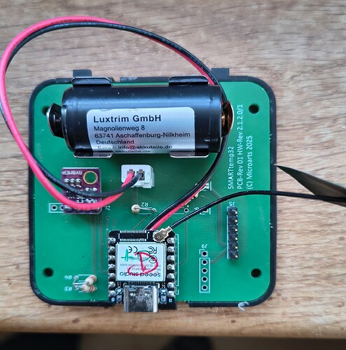
There’s not much to show:


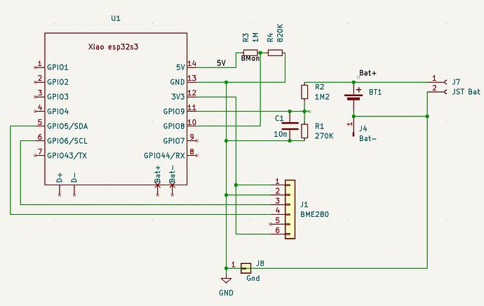
May be I’ve got problems when the battery is installed but the battery cable to the XIAO is not connected. There might be the full battery voltage supplied to RTC_GPIO_09 if the voltage devider R2/R1 is not grounded. I’ve to check the PCB…

1 Like

Hi there,

Looks pretty Steller to me. :+1: How confident are you on the Battery Pad connections? Sounds like they may be not 100% You can Power the sensor from the Xiao 3.3v if it works at that VCC? you wouldn’t need the Voltage divider, etc.
first as-is…
Also have you tried to connect the GND battery PAD to the rest of the GND’s.(looks Isolated) You should do that. and try it again.

my .02
HTH
GL :slight_smile: PJ :v:

Thank you again. I’m quite confident in the soldering of the bat pads. I double checked it and fixed it with hotglue.
The voltage divider R2/R1 is for monitoring the battery voltage. The other voltage devider R3/R4 is to detect an external 5V power supply (USB). In the case of using an external power supply, the sensor will work in a more power consuming mode: Not going to deepsleep, staying connected to the WIFI and publishing the measuring values not only to a MQTT broker but also by it’s website, collecting data from other ESP-NOW sensors and publish them as well.

The GND pad of the battery is connected to the GND of the XIAO if (and that may be the problem) the cable from the XIAO bat pads is connected to J7. The question is what happens in the following scenario while assembling the sensor: Battery is installed (4.2V), but the cable is not connected to J7? Then I will have about 800mV coming from the bat monitor voltage devider to RTC_GPIO_09 but the XIAO is not powered at all because of the missing connection to the battery. May be that grills somthing inside the XIAO soc?

I reported this post to Seeed Technical they are looking into it

Hi there,

Yes, I suppose that is indeed possible. In this case if you assemble and use a USB-c power bank connected, the Xiao’s battery charging circuit would protect from that, when connected. Sux tho 5 units? hopefully they can look too and make some suggestions. Probably put a diode in there.

The more i look at it GPIO9 is hitting me funny.

Let it marinate a while…

GL :slight_smile: PJ :v:

Hi there,

Ok, So FWIW…
The default hardware I2C pins on the Xiao ESP32S3 are:

  • SDA (Data)GPIO6 (D6)
  • SCL (Clock)GPIO7 (D7)

I2C Wiring (Recommended)

BME280 Pin Xiao ESP32S3 Pin
VCC 3.3V
GND GND
SDA D6 (GPIO6)
SCL D7 (GPIO7)

:pushpin: Pull-up resistors (4.7kΩ on SDA & SCL) are recommended but often already included on BME280 modules.

can you try this Code?

#include <Wire.h>
#include <Adafruit_BME280.h>

#define SDA_PIN 6  // D6 (GPIO6)
#define SCL_PIN 7  // D7 (GPIO7)

Adafruit_BME280 bme;

void setup() {
    Serial.begin(115200);
    Wire.begin(SDA_PIN, SCL_PIN);  // Initialize I2C with custom pins

    if (!bme.begin(0x76)) {  // Try I2C address 0x76 or 0x77
        Serial.println("BME280 not found!");
        while (1);
    }
    Serial.println("BME280 Initialized!");
}

void loop() {
    Serial.print("Temperature = ");
    Serial.print(bme.readTemperature());
    Serial.println(" °C");
    delay(2000);
}

Change 0x76 to 0x77 if your sensor uses a different I2C address.

sure you can pick any pins, but must call them out…

#include <Wire.h>
#include <Adafruit_BME280.h>

#define SDA_PIN 5  // GPIO5 (D5)  <<<<<<<< :grin:
#define SCL_PIN 6  // GPIO6 (D6)  <<<<<<<<< :blush:

Adafruit_BME280 bme;

void setup() {
    Serial.begin(115200);
    Wire.begin(SDA_PIN, SCL_PIN);  // Initialize I2C on GPIO5 (SDA) & GPIO6 (SCL)

    if (!bme.begin(0x76)) {  // Try I2C address 0x76 or 0x77
        Serial.println("BME280 not found!");
        while (1);
    }
    Serial.println("BME280 Initialized!");
}

void loop() {
    Serial.print("Temperature = ");
    Serial.print(bme.readTemperature());
    Serial.println(" °C");
    delay(2000);
}

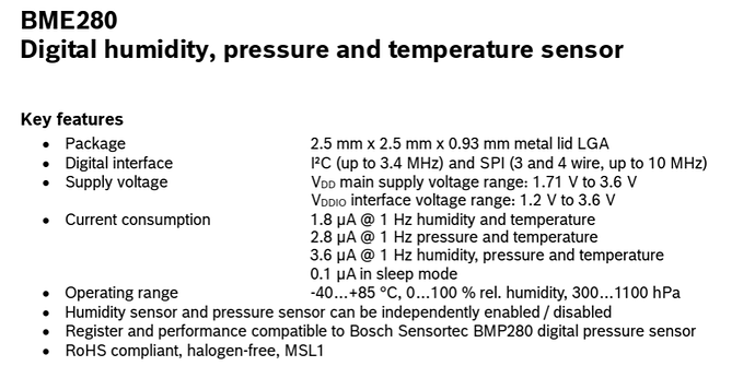
So you looking for lowest power then , instead of speed. I2C vs SPI
3.4HhZ or 10Mhz. .1 ua sleep …WOW :wink:

HTH
GL :slight_smile: PJ :v:

This may be a dumb ask , but have you tried it without all the Battery monitor stuff. Just the Xiao , Battery and Sensor? and I’m NOT a fan of that Battery :grin: