Seeed Studio XIAO ESP32S3 Sense - battery problem

The GND pad of the battery is connected to the GND of the XIAO

Hmm, that doesn’t sound right. The GND pad of your battery should be isolated with the XIAO’s GND Pin.

Battery is installed (4.2V)

We recommended the 3.7 - 3.8 V battery, check our wiki about the bat usage guide:

And 10 of 15 sensors worked great on your batteries, are those 10 sensors all based on XIAO ESP32S3?

Perhaps for easy cross reference, you can try switching a 3.7V Lithium battery with JST connector, try powering XIAO in the BAT pad directly and see if you can get a stable 3.3V output on the pins you wish to use.

1 Like

Indeed I got this WRONG! , DO NOT common those GND’s (isolate the Battery) I did this for extra drive current for a FET connected relay and needed to use the battery directly, The Xiao didn’t like it, It does work However it is prone to oscillations on the BASE or Gate forget which, but that was connected to the relay, If you touched it with your finger it would CHATTER the relay fierce
:face_with_hand_over_mouth:

I do LOVE me a 3.85Vdc Round Lipo battery 450Mah (with O&U prot)
Xiao likes it too. Last for over a month on single charge seems the 450Mah is the sweet spot for the charge controller in there.

@Wobex Your on the hunt you will get it.

GL :slight_smile: PJ :v:

OUR AI boi says this:
On the Xiao ESP32S3, the battery GND (BATT_GND pad) should be isolated from the main GND unless properly managed.

:mag: Why Isolating BATT_GND Matters?

  • The battery pads (VBAT & BATT_GND) are part of the power management circuit.
  • Connecting BATT_GND to the main GND directly bypasses the built-in charging and power protection.
  • This could lead to incorrect voltage regulation, possible short circuits, or even prevent proper battery charging.

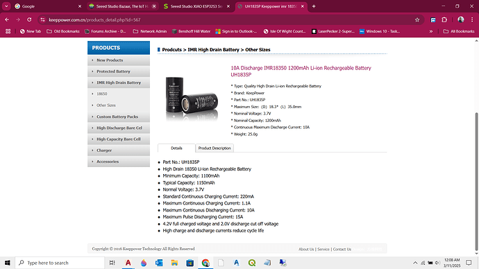
take and save in 3 seconds is probably a heavy lift and the camera is known to draw power and heat… so i am thinking the battery doesnt have the horsepower or the staying power to handle that workload… you may try changing the speed to 30 seconds… but i dont think the battery has the amp draw capacity for that type of work

2v cutoff voltage is way below XIAO Brownout level… even thought is says it can deliver 10-15 amps… … I think the batteries are discharged or have an internal short … maybe try adding a capacitor across the power rail… also try applying 3.7v at the battery terminals from a power supply

Hi there,

LOL, I’m thinking the Wait on Serial is messing him up code wise?

HTH
GL :slight_smile: PJ :v:

I use RTC_GPIO_08/09 for measuring and USB voltage detection because I can isolate them from the Xiao’s IO-matrix and minimize the leakage current in deepsleep. See rtc_gpio_isolate(rtc-gpio-pinnr).
btw: the i2c communication and climate data measuring works fine.

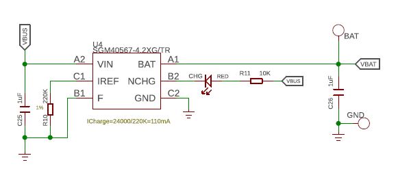
Well, looking to the Seeedstudio wiring diagrams of the Xiao esp32s3 there is no isolated GND for battery and Xiao. Look at the battery charging circuit:


The battery seems to be connected to the common ground, doesn’t it?
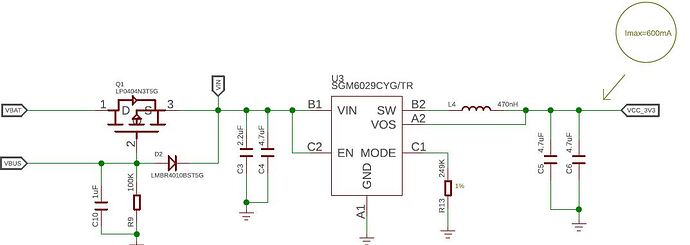
Let’s have a look at the voltage regulator circuit:

As you can see there is one input VBat (that is + bat) and one input VBus (that is the external 5V USB power supply). There is no isolated input für - bat. This circuit and the charging circuit are both referenced to common GND.
So if we really should isolate - bat from common GND I suggest to correct the schematics.

Yes of course, but the inbuild charger stops charging the bat at about 4.2V. So this is the voltage you got when the battery is fully loaded.

I appriciate your help!

i was going to ask… but he said it was a power issue… so i move forward from there

1 Like

Hi Wobek,
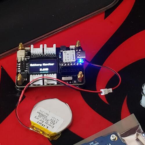
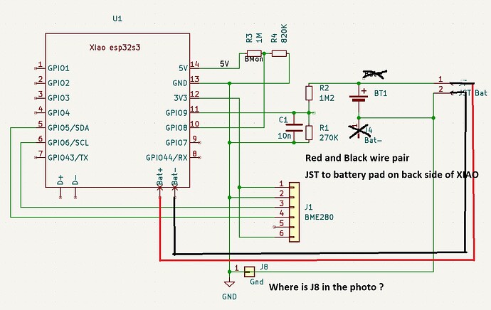
Comparing the photo to the schematic, I have a few questions.

  1. Is the actual circuit the schematic below? Or is it different?
  2. where does J8 appear in the photo? And is it connected?

Hi everyone,

I’m considering buying the Seeed Studio XIAO ESP32S3 Sense for a wearable camera project that takes pictures every 30 seconds, stores them locally, and uploads them to the cloud when charging for daily activity classification. Before purchasing, I want to understand how to power it with a battery, preferably without soldering.

I saw others had issues running it on battery alone—does anyone have a reliable setup?

A few questions:

  1. Which battery should I buy? I couldn’t find one on the Seeed store.

  2. How do I connect it without soldering?

  3. Will it power on automatically from a battery, or is extra setup needed?

Any beginner-friendly advice would be greatly appreciated! Thanks!

Thank’s for your question! J8 is not existent on the PCB. And bat+ / bat- is exactly connected via J7 like you added it.
The additional pin header J5 that you can see in the photo is to connect an e-paper display. It is not part of the schematic.

Since the actual device is not on my desk, it may be difficult to give reliable advice.
Use the simplest Blink sketch to see how it works with a USB connection, but not with a battery. Be sure to use the following sketches.

void setup() {
  pinMode(LED_BUILTIN, OUTPUT);
}

void loop() {
  digitalWrite(LED_BUILTIN, LOW);
  delay(50);
  digitalWrite(LED_BUILTIN, HIGH);  
  delay(50);
}
  1. Both JST and USB are connected and USB is connected to PC
  2. The battery is charged and the red LED blinks about every second.
  3. The yellow LED will flash every 0.1 second depending on the bulink sketch.
  4. Once confirmed LEDs, disconnect the USB from the PC.
  5. The red LED will turn off and the yellow LED will flash every 0.1 second.

If Blink does not work with batteries, measure the voltage according to the following procedure while running Blink without USB connected.

  1. XIAO’s 3V3 pin
    2.The metal part of the terminal of the red wire of JST
    3.The battery’s positive terminal
    (Be sure to connect the black probe of the multimeter to the GND pin of the XIAO, not to the appropriate GND)

If you check, let us know the results.

1 Like

Wobex,
Can you post a close-up photo of the GYBMEP board and resistors R1, R2, R3, and R4 so that we can see their color codes, and the battery label?
We can check the resistor values and see if LDOs, pull-up resistors or level shifters are implemented on the GYBMEP.

Thank’s msfujino!
The BME280 breakout boord has no LDO and no level shifters, but 10K pullups on SDA, SCL and - in the 6-pin version, which is also availabe - CSB and a 10K pulldown on SDO which is the i2c address select bit in i2c mode. So thank you for this hint. I connected SDO permanently to 3V3 of my PCB. If I use the 4-pin breakout board as shown in my photo there will be no problem because the the CSB and SDO pins are not existent. Using the 6-pin version would lead to a leakage current of 3V3/10K = 33µA via SDO. Not good - one more thing to keep in mind for the next PCB version.
The resistor values are correct - minimum quadrupple checked! As I wrote: If powered by USB all devices work fine. Climatic data measuring is plausible, battery voltage monitoring is surprisingly correct (it’s a quite high impedance voltage divider!), deep sleep and necessary time correction works as expected. The e-paper display (J5 in the photo) is driven correctly and yes even the charging of the batteries is ok.
But a few devices simply won’t run on battery. Same code, same hardware. Yesterday I checked again as you suggested with a blinky program. I erased the flash and uploaded the five line blinky program. It ran correctly if powerd by USB only. It ran correctly if powered by USB with a fully charged battery inserted, the charging LED blinked as expected. If I pulled the USB cable the Xiao stopped immediately - no more blinking. With battery inserted and USB pulled I could measure 3.3V from the 3V3-pin of the Xiao to it’s GND pin but the device did simply do absolutely nothing. I allready described this behavoir.

And then out of the blue sitting for some hours on my shelf of electronic waste - battery still inserted - that mean little thing started to blink! Gosh!

We came to the following decision: Given that let’s say slightly quirky behavior (which I’m quite sure now is caused by some deep sleep bugs - I just read an espressif document about flash behavior in light and deep sleep which really puzzled me) together with the almost unreachable boot and reset pushbuttons and the uncomfortable battery connection (yes I know, we can do a better PCB to solve this) we will be looking out for another platform. Which is a pitty because the Xiao really is a neat little sexy thing.

Well, the prototype series of 15 devices now has been manufactured and we will do some long time testing with the flawless running devices. The quirky ones are going to our student’s microcontroller lab - they should have the time and the motivation to find out, what was going wrong. If so I will let them post their results here.

Thank you all again for your help!

One last question.
If I run the problematic device with just XIAO and battery, without mounting it on the board, will the same problem occur? In other words, is the problem with the board or with the XIAO?

2 Likes

Good question!
The boards were assembled by two students and we only encountered the problems very late because they tested - very optimistic - USB powered only.
Since then we change our modus operandi:

  1. Upload program an web files to the unmounted pure Xiao
  2. Test the basic functions: Configuration web site, deep sleep, MQTT publishing, will the onboard LED live or die?
  3. Solder battery cable to Xiao
  4. Test the bassic function again USB and battery powered! Bat pad soldering is prone to mistakes!
  5. Glue battery cabel, solder pin headers carefully
  6. Put Xiao in a fully equipped breadboard test environment which emulates the PCB board and test all functions running on USB and running on battery. Basic functions, measuring of climatic data, battery voltage monitoring, battery charging, ext 5V detection, and for some driving e-paper display
  7. Assemble PCB board with all peripheral components and the tested Xiao
  8. Do the final test run.
    We did this with the last 4 or 5 devices and they all were running flawlessly. So I tend to think that we have no board problem. (Ok, I have to rethink the inbuild battery protection but… uhh, no I think that can’t be a problem)

We will unsolder a Xiao from a quirky device and do the test you suggested. It will take a while but I’ll report back.

1 Like

Two tips.

  1. If the BME280 board without LDOs is selected, the consumption current will be reduced by about 20 uA.
  2. When S3 is in sleep mode, is BME280 also in sleep mode?
1 Like

Man, You definitely got a handle on this, I did some looking and found out about “Forced” mode Saves running power based on the sample rate! , You knew that … :exploding_head:

According to the BME280 datasheet, the typical power consumption is based on the data refresh rate, which is normally quoted for 1 Hz operation.

Since the provided code reads data at 0.5 Hz (one sample every 2 seconds), the power consumption will be lower than the values listed for 1 Hz operation.

FROM the datasheet…
Average current consumption (typ.) (1Hz data refresh rate)
1.8 μA @ 1 Hz (H, T)
2.8 μA @ 1 Hz (P, T)
3.6 μA @ 1 Hz (H, P, T)
T = temperature
Average current consumption in sleep mode
0.1 μA

The BME280 power consumption scales approximately linearly with sample rate. The provided typical values at 1 Hz are:

  • Humidity + Temperature (H, T): 1.8 μA
  • Pressure + Temperature (P, T): 2.8 μA
  • Humidity + Pressure + Temperature (H, P, T): 3.6 μA
  • Sleep mode: 0.1 μA

Since the given code reads only temperature (bme.readTemperature()), it falls under T-only operation.
At 1 Hz, temperature-only mode would typically be around 1.8 μA.

Since the sample rate in the code is 0.5 Hz (half of 1 Hz), we can estimate the average current draw as:

1.8 μA
-----  =0.9 μA (approximate)
  2

  • BME280 in Sleep Mode (Most of the Time)
    The BME280 automatically enters sleep mode (0.1 μA) between measurements.
    Since the delay(2000); is much longer than the sensor’s measurement time (~1.5 ms), it will be in sleep mode most of the time.
  • I2C Power Consumption
    If the microcontroller keeps the I2C bus active, there could be additional power drain from pull-up resistors (typically in the μA range).
  • MCU Power Consumption Dominates
    The BME280 is ultra-low power, so the MCU’s power consumption (e.g., nRF52840) will be significantly higher than the sensor’s sub-μA draw.

considering this: AI suggest this code :crossed_fingers:

#include <Wire.h>
#include <Adafruit_Sensor.h>
#include <Adafruit_BME280.h>
#include <esp_sleep.h>

#define SEALEVELPRESSURE_HPA (1013.25)

Adafruit_BME280 bme; // I2C

void setup() {
    Serial.begin(115200);
    Wire.begin();

    if (!bme.begin(0x76)) {
        Serial.println("BME280 not found! Check wiring.");
        while (1);
    }

    // Set BME280 to Forced Mode (low power)
    bme.setSampling(
        Adafruit_BME280::MODE_FORCED,
        Adafruit_BME280::SAMPLING_X1,
        Adafruit_BME280::SAMPLING_NONE,
        Adafruit_BME280::SAMPLING_NONE,
        Adafruit_BME280::FILTER_OFF
    );

    Serial.println("BME280 Initialized. Taking measurement...");

    // Take a single measurement
    bme.takeForcedMeasurement();
    Serial.print("Temperature = ");
    Serial.print(bme.readTemperature());
    Serial.println(" °C");

    // Configure ESP32C6 to wake up after 2 seconds
    esp_sleep_enable_timer_wakeup(2000000); // 2 seconds in microseconds

    Serial.println("Going to deep sleep...");
    esp_deep_sleep_start();
}

void loop() {
    // ESP32C6 will never reach here; it resets after deep sleep.
}

This code:
:white_check_mark: Uses Forced Mode for BME280 (auto-sleeps after reading).
:white_check_mark: Puts ESP32C6 into deep sleep for 2 seconds (instead of delay(2000);).
:white_check_mark: Wakes up using RTC Timer to read BME280 again.
:white_check_mark: Dramatically reduces power consumption!

Expected Power Savings

Mode ESP32C6 Power Draw BME280 Power Draw Total
Always On (delay(2000)) ~20mA ~1.8µA ~20mA
Forced Mode (BME280 auto-sleeps) ~20mA (active) 0.9µA ~20mA
Deep Sleep Mode (ESP32C6 sleeps) 10-20µA 0.1µA 10-20µA

:battery: Massive power savings! Your battery will last MUCH longer. :rocket:

I’ll be testing it time permitting , I have a BME280 here somewhere
I thought it worthy a highlight :point_up:

HTH
GL :slight_smile: PJ :v:

1 Like

PJ,
Here is an example of nRF52840, previously reported.

1 Like