I am using a 2-channel SSR that requires 5V to operate. If the S3’s 5V pin is connected the S3 will NOT REBOOT after power is lost. Here are a few grabs:
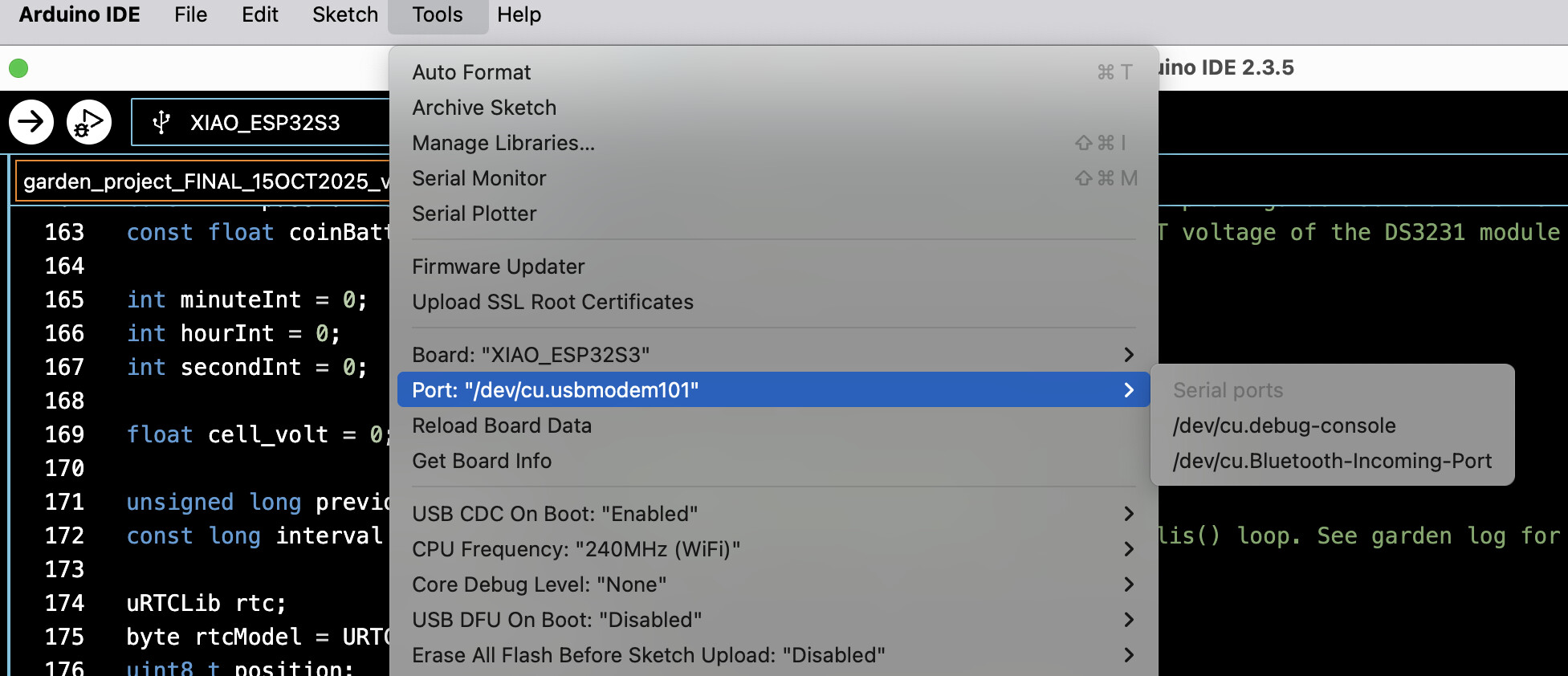
The above image shows that the port is missing because the 5V GPIO is connected to the SSR.
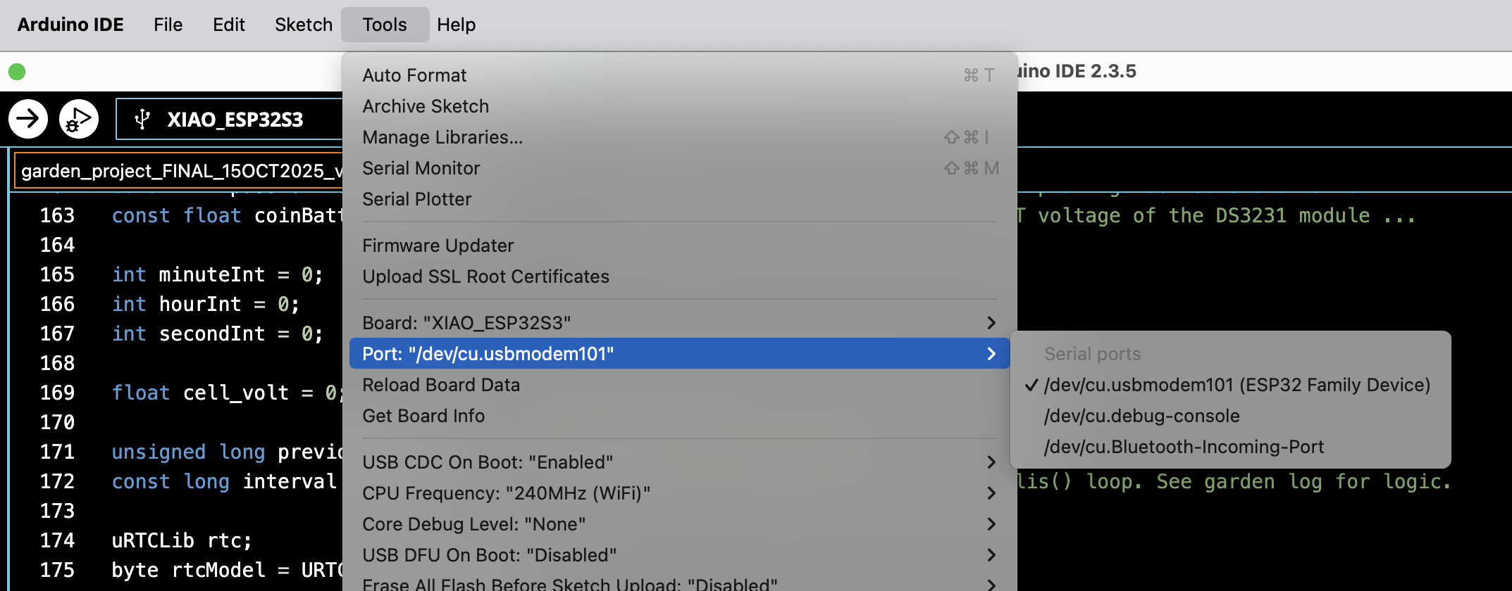
The above image shows that the port has reappeared because I disconnected the 5V hookup wire from the 5V GPIO.
Does anyone have a solution to this?
Thanks!
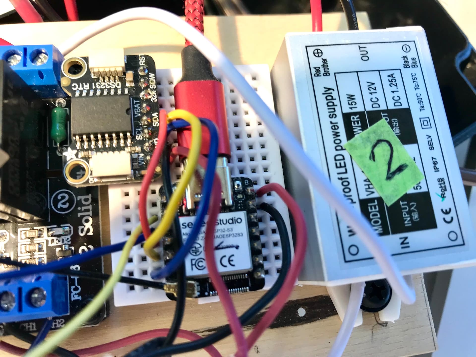
Here’s a grab of my board
The red lead is connected to the S3’s 5V GPIO.
Will search for 3.3V relays that I hope will fit on my enclosure board.
The XIAO_5V pin must be used as either a 5V input pin or a 5V output pin. When USB is connected, the XIAO_5V pin functions as a 5V output pin, so do not connect an external 5V power source. When USB is not connected, the XIAO_5V pin functions as a 5V input pin, allowing you to connect an external power source to supply power to the XIAO.
How is your wiring configured?
Thank you for getting back to me on this issue.
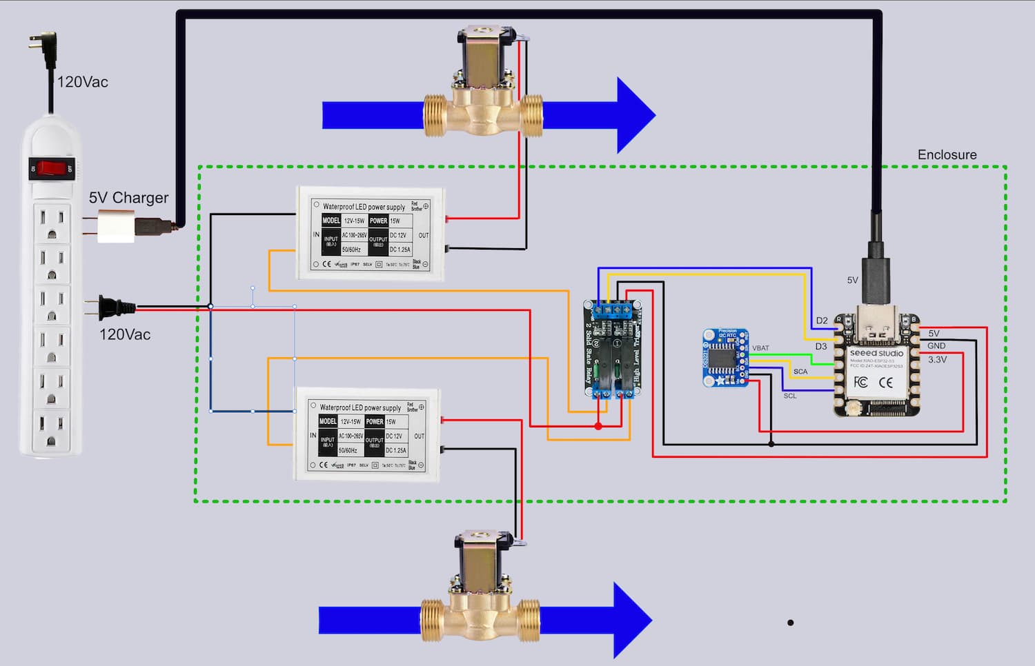
I am using the 5V pin as an output pin as shown in my hookup diagram shown next.
As seen the 5V pin is powering the solid-state-relay (SSR). The circuit works as designed except when power is lost the S3 will not restart because the port is unavailable as I showed above. I think I can overcome this by using a buck-booster but would rather not if this problem can be resolved.
Thank you for your help.
XIAO’s GPIO operates at 3.3V, so the SSR control input must also be 3.3V. Alternatively, a 3.3V-5V level converter is required.
EDIT:
Looking it up on Amazon, I found the following description. It might just barely work with LOW=0V and HIGH=3.3V.
★High Level Module: 0-2.5V state low level relay ON, 3.3-5V state high level relay OFF; Low Level Module: 0-2.5V state low level relay OFF, 3.3-5V state high level relay ON.
Thank you for the feedback.
Yes, I know there are some relays that will work with 3.3V power, but I do not have one of those. I will try 3.3V-to-5V (buck) converter tomorrow and see if that will be sufficient to power the SSR.
I will report back tomorrow with the results. Thank you.
Sorry for my late response. Other connected issues took me away from this problem.
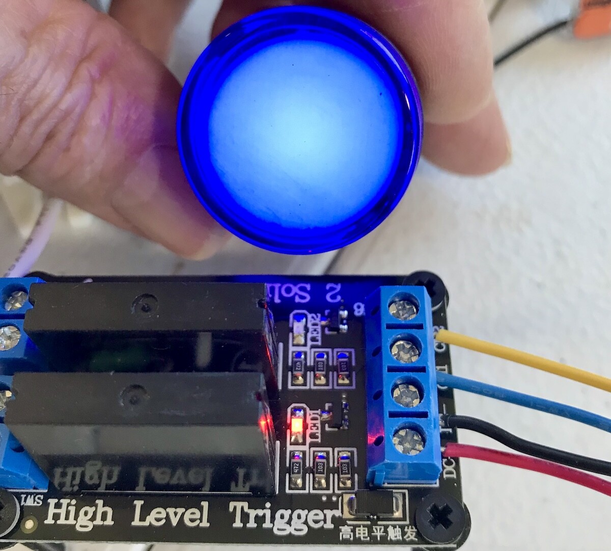
OK I have rechecked the SSR that I have and it will not work when powered by 3.3V. I inserted a 3.3V-to-5V buck booster between the S3’s 3.3V pin and the SSR’s power pin and the SSR worked as it should. No problem as seen next.
Above you see the channel-1 in operation with lit blue 12V LED.
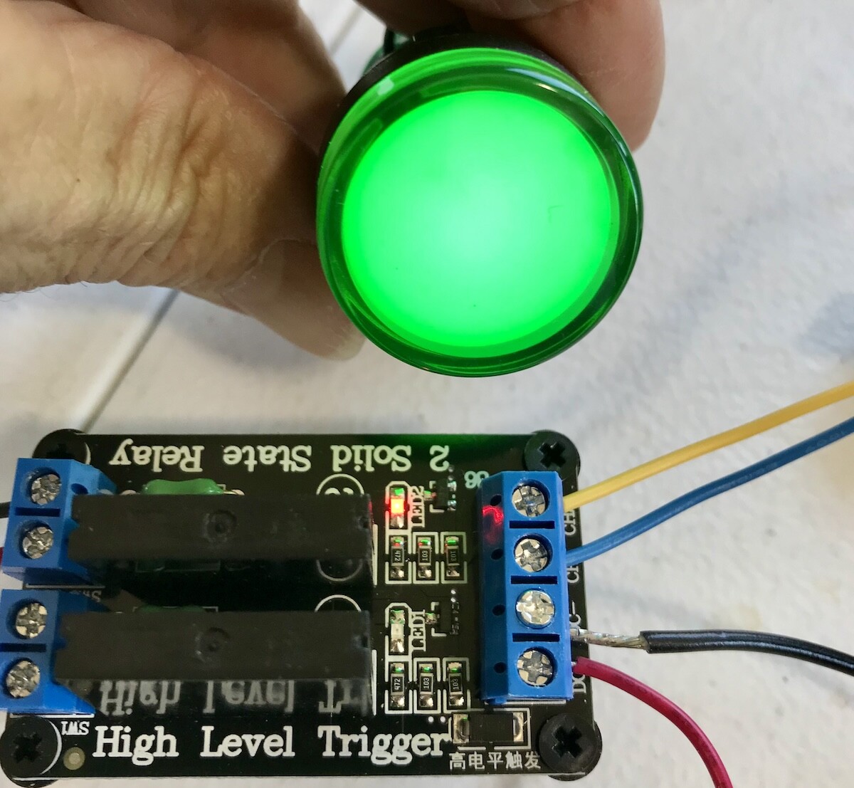
Above you see channel-2 working as well.
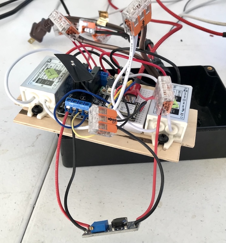
Here is a grab of the booster in place:
Fortunately, I have enough head room in my enclosure so the addition of the voltage booster will not be an issue.
I sincerely appreciate your help.
What I meant to say was:
・The SSR board requires a 5V power supply.
・Since the control signals are 3.3V to 5V, it should work with XIAO’s 3.3V output port.
And whether it works or not should be confirmed by the blinking LED on the SSR board.