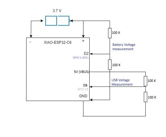
I am reading the battery voltage from the battery terminals under the board through a voltage divider and into an input ADC pin. I have a 3.7 V battery. See my attached simple schematic.
I am using 100K resistors in series, so when the battery is full, I read around 1890 mV from the ADC input.
However, when the battery is completely disconnected, and only USB is connected, I still read 1800 mV across these terminals. Is this normal? I was expecting 0 V if no battery is connected there.
But, If I drain the battery down to 3.2 V, and connect it, even if the USB is connected, I then get the correct battery voltage level reading of around 1600 mV via the ADC pin.
Now I can’t simply detect if a battery is connected or not. Or am I doing something wrong here? Thanks
i have not verified this but:
shouldnt you connect your measurement circuit to the - of the battery?
if you use the board-gnd you‘re reading the current board voltage, no matter where it comes from.
Greetings Boones
@TinkerDoc That’s a good point. However, I moved the ground connection to the negative terminal of the battery connector instead, and I have the same result.
I am reading 1985 mV on my input when no battery is not connected. This means that there is a voltage of around 3970 mV at the battery terminal.
When I connect the battery, I am then reading 1600 mV on my input, which is a true reflection of the battery voltage in its current state moment which is at 3200 mV.
Is this normal?
dunno if its normal, i do it way different, but it seems that you measure the boards voltage not the battery.
i will check on this the next days (reading the schematics, do some experimentation etc., because im curious too now.
i will tell you what i’ve found out. … if any
@TinkerDoc Thanks. It will be interesting to hear about your findings, and if you have any recommendations.
Hi pablo888,
When the battery is connected, analogReadMilliVolts() function reads the battery voltage.
I am reading 1985 mV on my input when no battery is not connected. This means that there is a voltage of around 3970 mV at the battery terminal.
When the battery is not connected, analogReadMilliVolts() function reads the output voltage of the charge controller SGM40567. In other words, it reads the voltage of the C9 1uF being charged instead of the battery.
Note that the voltage readings include errors in the voltage divider resistors and AD converter, and may differ by 10 mV or more from the voltage value measured with the multimeter.
Hi @msfujino .
Thank you for your reply.
In my case i’m not actually using Arduino code. I created my own application in C using ESP-IDF.
From what I gather from your response, the behavior which i’m observing in my project is therefore correct?
No battery connected = I’m reading the voltage of the charge controller.
Battery connected = i’m reading the battery voltage.
By the way, analogReadMilliVolts(), does this directly read the battery terminal / charge controller? Or it’s still reading via a voltage divider feedback to an input GPIO as I have it? I guess it’s a wrapper to allow easy reading of an analogue input.
I think both are correct.
analogReadMilliVolts(), does this directly read the battery terminal / charge controller? Or it’s still reading via a voltage divider feedback to an input GPIO as I have it?
Reads the GPIO voltage through a voltage divider resistor.
The advantage of analogReadMilivolts() function is that the calibration recorded for each chip is applied.
@msfujino Great info.
My problem is that my devices will be hidden way from physical access most of the time, and I will be reading voltages via Matter over Wi-Fi.
I can detect if the USB power is connected or not.
However, it will be difficult to detect if a battery at full capacity is actually connected or not when USB power is connected at the same time.
hey there… sorry, been a while, cause i worked on a cpython driver for mmWave devices
I tried around a bit… what do you need is a P-MOSFET-Switch which changes between charging and measure circuit…
if the charger is connected, the FET need to be deactivated to not read the charging state.
I do not have a circuitdesign-proggi installed currently, but here the general description:
USB->charging controller->battery->P-MOSFET(+V-Divider) where you read the voltage->GND all of the above
The Gate-Pin will be connected (via Voltage-Divider) so that the mosfet will close if the usb-power is connected, the divider for battery-testing can be connected to the out of the p-fet, then you can read the battery if there is no cable connected, without being interrupted but will turned of from the usb-source (cause it’s closed by the p-fet)
hope this helps a little
Greetings
Hi TinkerDoc,
If possible, it would be easier to understand if you could make a simple schematic (in freehand).
1 Like
