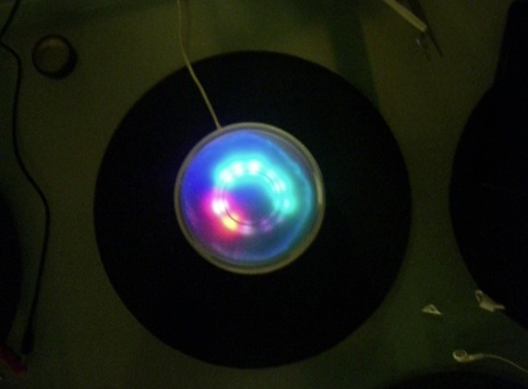
A LED clock that shows the current time in hours and minutes, and does a crazy awesome swirly pattern to indicate seconds passing. The two lit red LEDs indicate the hour, and the two lit blue LEDs indicate the minute. The seconds are shown by a green spinning pattern that makes one revolution every 5 seconds.
Instead of using the Rainbowduino for powering an LED matrix, I decided to try building something different out of discrete RGB LEDs. I powered each one by connecting three of the terminals (red, green, and blue) to a PWM channel on the Rainbowduino’s source header. The ground terminal of each was then connected to it’s own constant current channel. To control the colors separately, the LEDs were turned on one at a time for about a millisecond by pushing a pulse through the first and second shift registers, and changing the PWM duty cycle for each.
The microcontroller then just keeps track of the time, and adjusts the color of each LED periodically to show the hours and minutes and seconds. I also added a speeded-up mode that forces it to count time at 10X the speed. This is a little pointless when using it as a clock, but does look pretty cool.
The attached schematic shows the LED connections on the daughter board that fits on top of the Rainbowduino. Although the lights looked pretty awesome on their own, I diffused the light coming from them with a frosted piece of glass floating about an inch away from the LEDs. The edge of the glass creates the illusion of two identical rows of lights underneath, and spreads out the light to make the display look more connected.
Demo video here
[size=150]http://vimeo.com/6941882[/size]
Most of the time and lighting is done in hardware, using timers and interrupts. Each channel (red, green and blue) is controlled with one of the PWM channels, two on Timer0 and one on Timer2. The 16-bit timer, Timer1, is used for keeping track of the time. I calculated the frequency and capture value needed for an interrupt to occur every second ( to a reasonably high resolution), and then incremented the second, minute and hour every interrupt.
Another interrupt from this timer goes off about every millisecond, and controls which LED is lit up at any one time (yes, there’s actually only one on at a time!). This clocks a pulse through the first two shift registers (The ones on the red and blue channels of the Rainbowduino), and adjusts the three PWM channels to the correct duty cycle. A lot of tweaking was necessary to get the timing on this part right. Too slow, and the lights flicker like crazy, too fast and the PWM signal doesn’t change quickly enough, leading to leakage of color between LEDs.
I’ve made this design open-source, and I’m including the code along with this submission, since I think it’s a good example of controlling the Rainbowduino outputs manually and using the AVR timers to their full capabilities. I plan on expanding this project to create a better case, add more LEDs, increase the brightness and improve the accuracy of the clock itself.
Source code download
RainbowClock.zip (3.21 KB)