I have some problems with my GPRS shield on a Duemilanove: it doesn’t respond to AT commands at all.
Here is my setup: everything powered over USB from a Windows computer. No other shields mounted. SIM card and antenna installed. I am running the simple NewSoftSerial based example and the jumpers are set correctly.
When I initially power the board on, only the PWR LED is on, After I press the power key, first D1 comes on and then the red Status/D2 LED comes on. After about 10 seconds, D1 starts blinking very briefly every 3 seconds or so. D2 stays on.
At this point I try to send commands such as AT and AT+COPS with a CR efter (although I’ve also tried LF and CRLF). I have hooked up a Saleae logic analyzer and I can confirm that the Arduino is, in fact, sending the AT\r command correctly on pin 8, when I hook up the async serial analyzer and set it to 19200 8-N-1. The GPRS never responds with anything on pin 7 (or, for that matter, pin 0). I never see the RDY message that I’ve seen in some screen shots; in fact pin 7 is completely quiet, at least when captured at 1 MHz which should be enough to capture serial.
Are there some things I can do to troubleshoot this?
Ok, here’s an update: I managed to get the shield to send an SMS using the hardware UART, using the example from the wiki.
However, when I hooked up the logic analyzer again, I noticed that the Arduino can send commands (and they work because the SMS is actually sent), but never receives any responses from the shield on pin 0.
I am unable to communicate with GPRS shield via terminal program. All jumpers are in right position, SIM-card in place and working (tested on real phone), Arduino connected to USB and external power source. Tried different terminal programs with no luck.
After pressing PWR key on GPRS shield in 20-30 seconds status become red and green “Net” stops blinking. As I understand from other reports this is ok status: network found and connected.
I successfully sent SMS from the shield in Xbee mode. But unable to communicate with the shield in terminal program. I used to own 2400bps modem, so I know how to use terminal programs and comminicate with modems via AT commands quite well.
I have Arduino Duemilanove clone, it works perfectly in all tutorials from Arduino’s site.
You can try the following AT commands, and see if this can fix your problem.
ATQ0 /r/n //TA transmits result code
ATE1 /r/n //echo mode on
AT&W /r/n //store the current configuration in profile 0
Send ATQ0, ATE1, etc., then send an SMS to my regular phone. (I have a version with both hardware UART and for newsoftserial, and they both work.)
Send ATQ0, ATE1, etc., then start the serial relay.
What happens: it can send SMS fine, but the serial relay doesn’t seem to work.
I have attached my Saleae logic analyzer to pins 7 and 8, put the jumpers in softwareserial mode, then recorded a logic analyzer session for each program. I have attached a zip file with these sessions in both Saleae and CSV formats. I have also attached the Arduino sketches I’ve been using.
What seems to happen: I can send whatever commands I want to SIM900, and the SMS program works, but I never receive a response on pin 7.
I am close to the edge of my technical abilities in debugging this, but I’m willing to follow whatever suggestions you guys have. I do have my logic analyzer that can work up to about 16 MHz, and a pocket digital oscilloscope if that helps. arduino-sketches.zip (1.57 KB) gprs-logic.zip (7.45 KB)
OK, no real new information, but I just received a Bus Pirate (what product btw!), and again I can successfully send SMS messages in 19200 8N1, but I never receive any data back from the GPRS shield.
Sorry about the inconvenience. I think you can try to upgrade the firmware of SIM900, please down load the firmware and tool (including how) from : garden.seeedstudio.com/images/8/ … d_tool.zip
To be clear: TX and RX go to pins 3 and 2 of RS-232, and I can provide power from the Arduino as normal during the upgrade process? Any other connections that must be made?
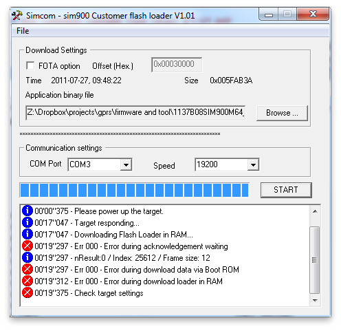
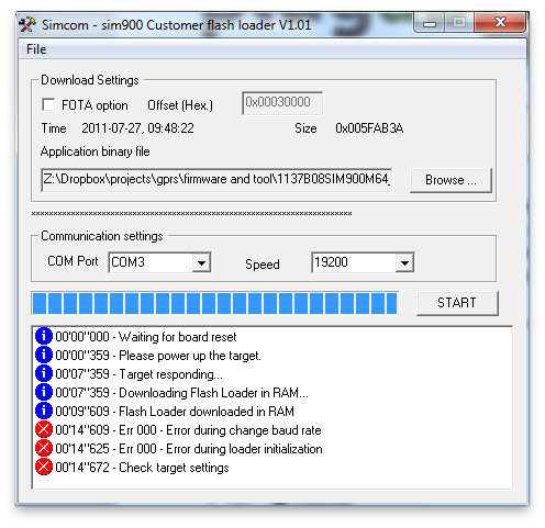
Thanks for the suggestion. I can’t quite get it to work, I get various different error messages and I’ve attached two.
I have connected pin 5 of the DB-9 RS-232 to ground, and pin 2 to the SIM900 board’s TX and pin 3 to the SIM900 board’s RX. (These pin numbers are looking into the male connectors on the computer end.)
Question: Is it ok to use the GPRS_TX and GPRS_RX pins on the SIM900 board, or do I need to use the actual TXD and RXD pins on the SIM900 chip itself?
Question: What is the exact procedure? I have tried various variations, but here’s what I am doing now:
Power on SIM900 board.
Press the power key, wait for the lights to be normal.
Press Start button in firmware update program.
I was not able to use the power key at all when GPRS_TX and GPRS_RX are connected.
You can use the use the GPRS_TX and GPRS_RX pins with UartSBee or equal.
GPRS_TX and GPRS_RX should disconnect from other purpose. After you connect the wire(here PWRKEY(PIN 1) of SIM900 should be connected to GND during the whole process), first press START of Simcom - sim900 Customer flash loader V1.01;(before this process the module is power down, completely disconnect from any power) ;then power up the module( connect to power ).
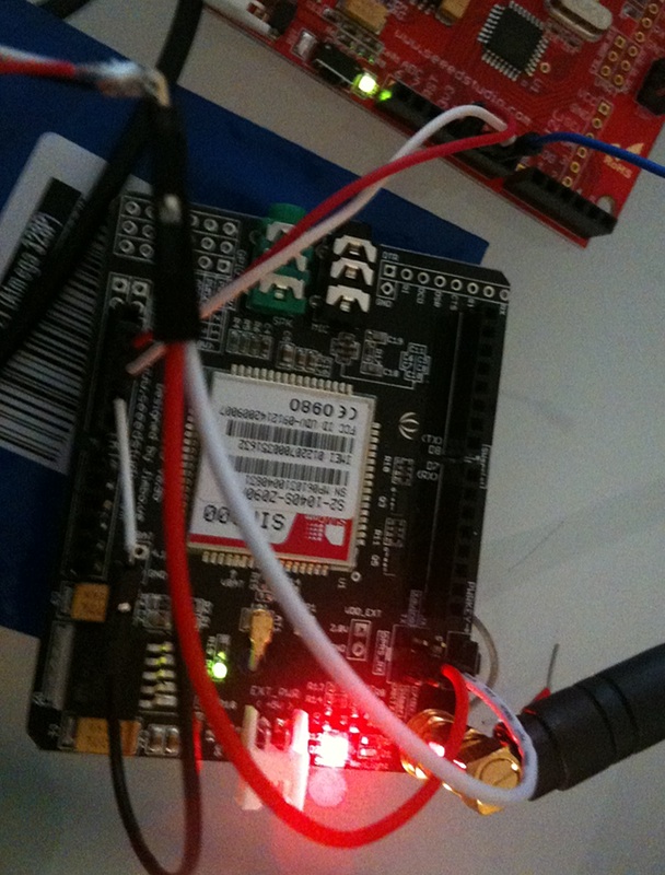
I am still trying to upgrade firmware. I connected the GPRS Shield to a USB to TTL UART cable that I obtained here. To test that my UART cable works, I used a terminal emulator to send an SMS. This worked, I received the SMS, but again (as usual) I never receive a response from the GPRS Shield to AT commands.
Things are now connected like this:
GPRS Shield power provided from a Seeduino
TX and RX directly to the USB/TTL cable from the GPRS_TX and GPRS_RX pins. I assume these go through the level shifter.
Separate jumper wire that I use to connect GND directly to pin 1 on the SIM900 chip.
For the various baud rates up to 115200, I do this:
Disconnect +5V from GPRS shield.
Reconnect +5V to GPRS shield.
Connect GND to pin 1 (PWRKEY) on SIM900 with jumper wire, hold it there (at this point the board starts powering up normally, netlight and status light up as if I had just preseed the button).
While PWRKEY is still connected to GND, press START in the updater.
Every time I get the message “Please power up the target”, at which point nothing happens.
I have also tried this procedure:
Disconnect +5V from GPRS shield.
Reconnect +5V to GPRS shield.
Pres START in the updater, wait for “Please power up the target” message.
Connect GND to pin 1 (PWRKEY), hold it there.
Every time, no reaction from the firmware updater. Also in every case, the Netlight and Status LEDs light up like they would normally do, and Netlight does off after 10-15 seconds.
Is there a different sequence of steps I should try?
Can I ask which baud rate you use for firmware updates?
edited to attach a photo of the setup; the TX and RX pins are only connected to my USB/TTL thing at the top left:
You can try to solder a wire to PIN1 of SIM900, and wire it to GND. In this way, you don’t need to pushing button all the time. By the way, when push the PWRKEY button PIN1 and PIN2 of SIM900 are connect together.
Yes, I noticed that in the schematic. I did actually connect PIN1 directly to GND and nothing else, as I described. I did not use the button for the upgrade process.
This afternoon I will probably try to connect the logic analyzer again to see exactly what the update tool sends over the wire.
OK, as I said, I didn’t use the PWRKEY button, I used a jumper to connect pin 1 directly to GND.
I have now tried to run the updater in 19200 and 115200 bauds, and listened in. In 19200 baud, the firmware updater keeps sending decimal 255 and never receives a response. In 115200, the firmware updater keeps sending decimal 22, and never receives a respond. I’ve attached the logs.
By the way, this document suggests that there is a different debug port UART on the SIM900 and that this should be used for debugging and firmware updates. Are you sure the firmware updater will work with the regular UART? updater-logic-logs.zip (15.7 KB)
Any one tested 1137B09SIM900M64_ST firmware? I installed here but cant use AT command, whats default baud rate for it? and where can we locate more doc about it?
======= EDIT =======
I solved here:
We must write 1137B09SIM900M64_ST.cla file, not .rar or .zip
After FW updated sim900 go to auto baud rate mode, use 38400 bps as baud rate to communicate, and send commands, using upper case: like ATI
You can setup default baud rate using AT+IPR=19200
During firmware update error occurred.
After that shield will not turn on (LEDs status and netlight not illuminated).
Is at sim900 firmware restoration mode?
I have the same issue: Sending SMS works, but I never receiver anything on the RX-line.
(verified by probing with a scope)
So I tried an firmware-update:
wire pwr(pin1) to GND
connect usb-TTL-seriell-adapter
start software, select COM, press “START”
connect the GPRS-Shield with 5V USB (with an 220uF elko).
But it failed the same way as guan’s “Screen Shot 2011-07-28 at 15.30.10 .png” descripted it.
I tried 19200,115200 and the default value (4…).
Maybe Offtopic:
After reading this: viewtopic.php?f=4&t=2444&p=9019 Does it only looks for me like dry soldered joint at the small 1206-NFETs (both problems!)