Hi, I’m working on a project where I need to have multiple esp32s3 sense boards powered off the same battery. My plan is to solder the battery to the battery pads in parallel, so each board should be able to draw from the same battery. My only concern is how this would interact with the built-in battery charging circuit — if I supply external power to one board (either via USB or 5v pin), it should still be able to charge the battery right? But the other boards will draw power at the same time and power on (which I’m ok with). I just want to ensure this won’t cause any problems for either the charging esp32s3 board or the other esp32s3 boards.
Edit: Follow-up question — let’s say I tie together all the VUSB pins so I can test the boards together over USB. I believe this will cause all 4 battery charging chips to try to charge the same battery — will this be a problem? Can I resolve this by instead put a diode on the battery pads on the auxiliary boards so they can only draw from the battery and not charge it?
I have examined the schematic and datasheet and it appears to be fine as long as you do not connect external power to more than one board at the same time.
If you are going to use it in your product, you should check it thoroughly.
Thanks, this is for a personal project, not a product. I took a look at the schematic but nothing jumped out to me — can you explain what the issue is? Powering from the USB should be the same as powering from the external 5v pin, no?
ah, sorry I edited the original question (see the follow-up edit). If I add diodes to the battery pins on the auxiliary boards, it should then be ok to supply external power to all the boards right? Since only the primary board will be able to charge?
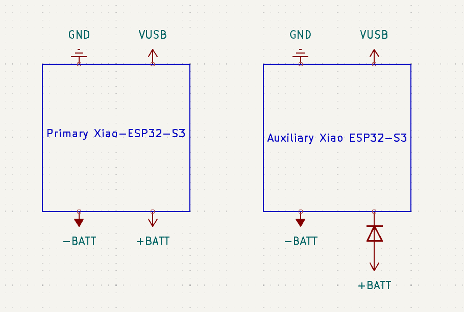
Something like this – both boards can be supplied external power for ease of development/testing, but only the primary board will be allowed to charge the battery. Do you think this will still cause issues for the aux board’s charging chip? Thanks!
Probably not a problem.
The charge controller SGM40567 operates when powered from VUSB.
The battery is connected via a diode to the output pin BAT of a working charge controller, but I do not know exactly how the controller behaves.
Perhaps the charge controller thinks that C26:1uF is a battery and charges it to 4.2V.
For example, C26, which is previously charged from the battery to 3.7 V via a diode, will only be charged to 4.2 V when the charge controller begins to operate. There should be no particular problem.