Here’s the solution I came to. I’m sure I’m making some assumptions, and trusting AI on many things I lack much experience on… but hopefully I’m not stretching the truth or making too many possible false assumptions or using wrong terms below (all I can say is it works for me lol). Also going to reiterate the problem all the way to the solution:
PROBLEM:
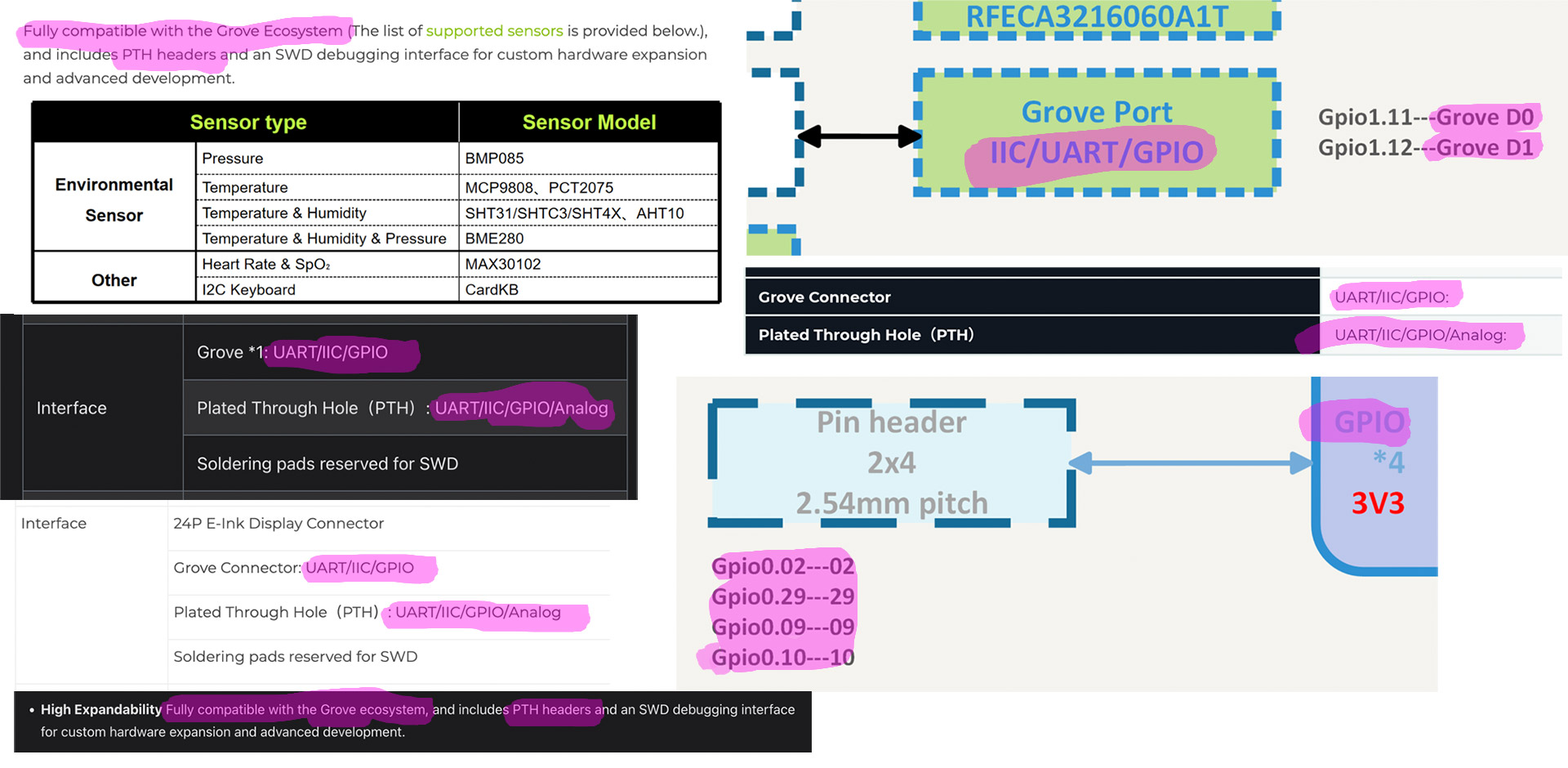
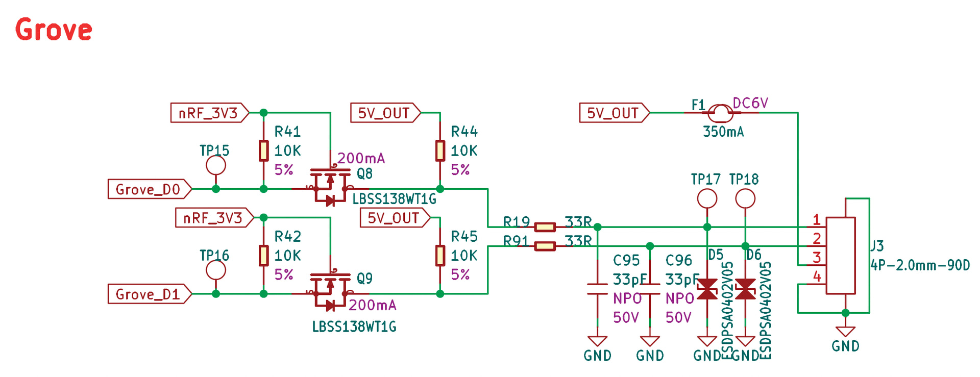
The problem with the Grove connector on the Wio Tracker L1 Pro is it will NOT work with ANY Grove module which triggers by sending a high trigger – since the Grove D0/D1 trigger pins are ALWAYS on high – and there’s NO way via software to make those trigger pins idle at low since they’re hard-wired to always be on high. This also means all the marketing terms Seeed uses to say they’re compatible with every Grove (I2C/UART/GPIO) module is completely false.
PROPOSED SOLUTION:
Since the Grove connector isn’t compatible with many types of modules, that only leaves the PTH pads as an option to get a high/low module to work (like the Grove PIR motion sensors I’ve been testing, but also maybe another ~20ish similar modules from Grove which use the same high/low triggering mechanism) – but the problem with those is Seeed never added the PTH pins to the resource files the Meshtastic Github uses to compile the L1 Pro specific firmware…
SOLUTION:
The ONLY solution I found (that doesn’t involve adding/removing/modding hardware) is to edit the code to enable those PTH pads, re-compile, then flash it to your L1 Pro… which will have to be done EVERY time the Meshtastic firmware is updated (which Alpha builds seem to be updated every ~2-3 weeks). For the record this is also WELL beyond what most casual users are able to do (or are willing to do I should also say lol), so I’m hoping I can get the below lines of code added permanently on Github so it’ll be this way, stock, moving forward.
CODE CHANGE FIX:
For the exact fix which made my L1 Pro work, I only had to add a couple lines to variant.cpp:
    // Exposed two pins from the 8-pin PTH GPIO pads for external sensor use
    2,  // D31 P0.02_DIO_AIN0 PTH GPIO pad
    29, // D32 P0.29_DIO_AIN5 PTH GPIO pad
I then used MacOS Terminal (Windows users would use PowerShell), added the above to variant.cpp, then compiled the new code and uploaded the modified firmware to the L1 Pro (I’m NOT going into detail about that process as that’s a lengthy topic on its own… but I will say ChatGPT basically did all that for me and I just pasted in and ran the code it gave to me – took about 20 minutes pasting in commands, and about 2-3 minutes of CPU time to actually compile).
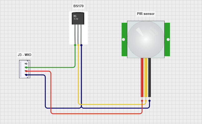
Once done that lets the PTH pads labeled 02 and 29 on the L1 Pro’s PCB be used as triggers. They sit idle at 0.0V. So to setup your compatible high/low-type detection sensor (which is NOT just motion sensors - there’s a TON of other types!) in the Meshtastic App you go into settings, Detection Sensor setting page, you would select Pin 31 or Pin 32 as the “GPIO Pin to monitor”.
Since the motion sensors I’m using also like 3.3v, I’m also using the 3V3 pad (3.3v) of the PTH, and the GND (Ground) pad of the PTH (so 3x total wires needed: power, ground, trigger) – so I’m not using ANYTHING on the actual Grove connector itself (all this involve soldering - which again, which many casual users can’t do).
OTHER REQUIRED SETUP FOR DETECTION SENSORS:
To have ANY type of Detection Sensor work you also have to have a PRIMARY text channel setup for that. Most default setups have the public LongFast setup as the Primary… you have to move that to a Secondary channel, and setup your Primary to be for the detection sensor (I used “Motion Sensor” as my name). It also has to have a 128 bit encrypted key.
In Detection Sensor settings the node with the sensor attached to it gets set as “Sensor”; and the node(s) you want to get the sensor text alerts 1.) ALSO have to have the same-named Primary channel 2.) HAVE to have the same 128-bit key 3.) Are set to “Client” (with enable notifications toggle set to ON).