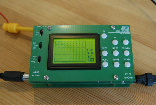
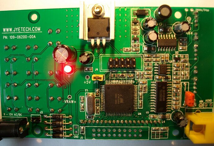
Madworm, did you try to powerup the scope with a usb cable, bypassing all the powerstage, as I did with my ftdi cable ?
Yes.
I’ve just upgraded the JYETECH scope from .070 to .080 flash, bootloader and firmware via ISP (not via serial bootloader don’t have an RS232 level converter handy) and the scope works OK with .080, except for one problem.
When the scope boots the splash screen says “No bootloader found”. When I first got the scope with .070 it recognized the bootloader on the splash and displayed the version. Tried going back to .070 which works OK too but now no “No bootloader found” on the splash again. I’m using AVRStudio4+ and AVR Dragon in ISP mode. Anyone else seeing this? Thanks for any replies - David
That’s normal. The bootloader protection fuse was not set, so you killed it by flashing the new firmware.
Hi Madworm, After I program the scope, I load the EEPROM, bootloader, and firmware files into AVR Studio and verify (only) each individually against the ATMega64 via the AVR Dragon in ISP mode. Each file verifies OK. If they all verify OK, then the bootloader must not be getting clobbered, right?
Even though all files verify after programming, there’s still no recognition of bootloader present on the scope’s splash screen. The recommended fuse bits enable BOOTRST reset vector redirection fuse. Also the recommended BOOTSZ1 & 2 fuse values set the bootloader section to the default 4096 words starting at 0x7000.
I presume you’re talking about lock bits to protect the bootloader, not fuses? I saw your batch file for AVRDude in an earlier post. Did you set lock bits to protect the bootloader after programming it? If so what were the lock bit values?
In any case, after programming do you see the line on the splash screen reporting a bootloader present and providing the version?
I suppose a safe programming sequence in AVR Studio would be:
- Verify device ID.
- Do a full device erase (only way to reset the lock bits).
- Disable auto-erase when programming flash.
- Program fuses.
- Program the EEPROM
- Program the bootloader
- Program lock bits to protect bootloader
- Program firmware
Maybe the lock bits just protect the bootloader from the program in flash and not via ISP programming? I just can’t figure out what to set the lock bits to. Programming and protecting a bootloader is obviously new to me.
I remember reading that the lock bits must be programmed after the fuses and the lock bits can only be reset by a full device erase. The fuses are set to preserve EEPROM during a full device erase, but that’s OK because we reprogram the EEPROM explicitly.
Any help is much appreciated. I really would like to get the bootloader back. I’m eventually going to mod the scope with an RS-232/logic conversion circuit so I can use the bootloader as well as download screen captures.
Best Regards, David
Yes, I meant the memory lock bits.
To protect the bootloader, you’ll have to at least disable write access to the bootloader memory in self programming mode. It’s in the datasheet somewhere, but easily found by looking for lock-bits. And yes, this only affects self programming. Using a programmer would overwrite it anyway. Your sequence seems correct.
Hi again Madworm,
After upgrading to .080 etc. with AVRDude via ISP is your bootloader showing up on the scope’s splash screen? Please answer this. Has anyone gotten the bootloader recognition in splash to work after ISP upgrade?
I had some time to review the whole lock bit, bootloader BOOTRST fuse issue (studied the data sheet and spent a lot of time reading posts on the AVRFreaks forum). Then tried a lot of logical combinations and permutations via ISP in AVR Studio. None of them brought back the bootloader.
Maybe JYE TECH made the booloader and/or application firmware such that it re-entrant disables the bootloader itself so nobody can use it on a generic ATMega64? Maybe the only way to bring back the bootloader is to load only the bootloader via ISP with proper (?) lock bit settings and then use the serial bootloader (not ISP) to program the EEPROM and application firmware?
At a minimum for self-programming via bootloader it seems the lock bits must disable SPM in the bootloader area and allow LPM. Allowing LPM in the bootloader area lets the application area firmware read and report that the bootloader is present and what the version is. And that both SPM and LPM be enabled for the application area so the bootloader can write new application firmware via SPM and verify what is written via the LPM instruction. This would be it seems 0xEF for lock bits instead of the no protection default 0xFF.
A few weeks ago I asked JYE TECH directly via Email how to get the bootloader back via ISP. I was rather detailed in my request. Never got a reply. I’ll try again and point them to this thread.
Thanks for the reply - David (BTW I’m GMT+7)
After upgrading to .080 etc. with AVRDude via ISP is your bootloader showing up on the scope’s splash screen? Please answer this.
Has anyone gotten the bootloader recognition in splash to work after ISP upgrade?
Yes it works with avrdude, but you have to disable chip erase when flashing the firmware (-D) or the bootloader gets trashed again. It got it working with the avrdude sequence I posted here.
Maybe JYE TECH made the booloader and/or application firmware such that it re-entrant disables the bootloader itself so nobody can use it
on a generic ATMega64? Maybe the only way to bring back the bootloader is to load only the bootloader via ISP with proper (?) lock bit
settings and then use the serial bootloader (not ISP) to program the EEPROM and application firmware?
No no, it works. My firmware was completely borked and flashing restored it including the bootloader. The scope has other issues, but I think this one has a bad chip which I will replace some day. Flashing works just fine.
A few weeks ago I asked JYE TECH directly via Email how to get the bootloader back via ISP. I was rather detailed in my request. Never
got a reply. I’ll try again and point them to this thread.
Just flash it !
Do a complete chip erase, write the bootloader, write the firmware (with chip erase disabled!), write the EEPROM data.
I found a good link to English documenation for the JYETech 062 Digital Storage Scope:
jyetech.com/Products/LcdScope/eDSO062.html
Here you will find:
Operating Instructions [v05]
How to Program the Scope with Programmer or Bootloader
Firmware
PC program for downloading codes via the bootloader
How to Use the External Trigger
My scope came with firmware -080 installed.
When I enter SIG mode and apply a signal, it triggers and then enters HOLD immediately.
If I press OK, it exits HOLD mode, triggers, and enters HOLD again.
Unfortunately, when HOLD is lit, pressing MODE brings up the “Save Capture” screen.
So, as a result, if you enter SIG mode it is not possible to exit it because you can’t get back to the MODE.
Actually, you can. Change the source signal to none so the trigger won’t trigger, and hold won’t hold so you can exit the mode.
It reminds me the suggestion I made to the moon : How about an indicator on the lcd to show when the scope is in snapshot review mode ? (or a blinking image (eg. 10ms every second off))
Thanks for the recommendation to change signal input to GND in order to avoid hold mode.
However, it still fails for two reasons:
- if the trigger level is low enough it seems to trigger anyway even with GND.
- There appear to be implementation bugs in -080 that cause the buttons to retain the secondary meanings even though HOLD isn’t lit. I see this frequently and I’m reasonably sure it’s a firmware bug that gets the secondary button state out of sync with the display of HOLD.
Aside from the apparent firmware flag bug, it would be nice if the secondary button meanings were push-hold rather than push, or alternatively, if push-hold on the buttons during HOLD mode would access the primary button meanings.
I’d be willing to work on these issues, but it doesn’t appear that the existing firmware source is available. Maybe that’s a hint to us to start a new firmware project for this scope, or perhaps just wait for the new color scope that’s been prototyped.
Leigh/WA5ZNU
Actually, there is one free firmware already.
See this post
although, it’s a bare one. Does someone already tried it ?
I’ve ordered this scope kit for two reasons: 1. seeing how well I fare with SMD soldering and 2. using the scope itself. Now the first requirement has been satisfied, soldering went without too much of a hassle, but the second requirement has not been met so far.
The scope boots up and shows the grid and options, but not the signal. I’ve connected it to the test signal with the options set as the manual suggests (see image), but nothing shows up (also checked the other pole of the probe, also nothing). Buttons and everything else work as far as I can check them. Occasionally just after powering up, the scope shows some scrambled signal that disappears after two seconds or so.
Has anyone any idea on what to check now? I checked the polarity of the diodes and such, which seem all ok. It did take some time and multiple attempts to solder U5 (TLC5510 a/d converter), could this have fried the component and caused this behavior? Any idea how to check for proper function of this IC?
Firmware is 06202.080 (which the scope came with).
Hey guys, new firmware out !
Just seen at jyetech.com/Products/LcdScop … mware.html
113-06201-090 [ 2009.09.28 ]
Fixed the known bugs in version -080.
I’ll give it a try.
I upgraded my modded version of the scope (this time using the bootloader and the windoze utility using virtualbox) and it seems to run fine. No strange hangs yet.
Still I can’t get the xmodem image download to work. It didn’t work with hyperterm as suggested in the manual. With minicom on linux xmodem complains about “checksum”. The serial port was set to 38400,8N1.
Updated to the new firmware. Still have to use the GND trick to get out of SIG mode, but it’s nice to see progress. Thanks!
I used a SparkFun RS232 “Level Shifter” board and a couple of junked headers from an old PC motherboard (superglued together to make 4 pins), and then some 90-degree pin headers mounted backward (to cut down on the sideways profile).
wa5znu.org/2009/09/LcdScope for pix
minicom uses rx to download data. Add “-c” as a option to rx
yeeeha ! Now it works ![]()
stty -F /dev/ttyUSB0 38400
rx image.bmp -X -vv -c < /dev/ttyUSB0 > /dev/ttyUSB0

Hi!
after i got it assembled it only worked for a couple of hours and then it stopped responding
i didn’t even had the chance to use so so i can do some measurements while it was still alive… ![]()
now only the backlight of the display and the red led comes on… i did some inspection to the
board and i also checked the +VRAW and +5V pads and the voltage looks fine… i really don’t
know what else to check
here’s a photo… i hope somebody has an opinion and can help with it.

