My scope is best described as “confused”. The save screen should only be available in HOLD mode, but quite often my scope goes to save screen in live mode and the screen gets overwritten by text and looks strange. I’ve sent jyetech a video of it, as they couldn’t open it on youtube. I’ll try a downgrade to 070 again.
As for the German firmware, I don’t know if there is any official support for it. I personally can handle the few English words on the scope
As of NOW jyetech provides these files on their website
firmware
bootloader
eeprom data
If you want to update the firmware and have access to a windows PC, download the updater and update using the bootloader! It also works using a virtualized windows XP (e.g. using virtualbox) and an FTDI cable or a moderndevice BUB (tested) or the equivalent from seeedstudio. You will have to build an adapter cable to match the USB adapter pinout to the 4pin serial connector on the scope. You have to add the serial connector yourself, the parts are not included in the DIY KIT.
Please note that once you have updated and decide to downgrade the firmware, the eeprom data won’t match anymore and you may get odd behaviour!
If you are on LINUX/MAC using a programmer and avrdude seems the only option right now, unless someone finds a way to talk to the bootloader with avrdude directly. The avrdude commands are describes a few posts earlier.
According to seeedstudio the front panel size mismatch is being addressed.
I’ll further investigate if the problems I have with the new firmware might be caused by a bad (unregulated) power supply I’m using right now. Maybe some changes in the firmware use tighter timing settings and make it prone to noise on the supply lines.
Nice cuts. What tool did you use to do those sharp squared line cuts ?
I think more of making a replacement cover board with ftdi chip and usb plug, that could be
linked to J5, and of course, adding an on/off switch to it.
I used a 1mm carbide bit. I have a Proxxon MF70 for little jobs like this
Could you test if you can crash the scope by excessively pressing buttons very fast for a minute or so? Like switching the timebase and mode/slope and so on.
On/Off switch. Not a bad idea. In my case that would be a reset button. If they had used a standard 10pin ICSP header, shorting pin5 to pin6 would cause a reset…
It seems the ATmega64 is only specified to work up to 16MHz and the scope uses a 20MHz crystal… I’m pretty sure that this could be a reasonable cause for it crashing all the time. A cpu passing factory tests at 16MHz may fail at 20MHz. Maybe most don’t fail, but some will and I guess I might have one of those.
I’ve been able to make it crash with the 070 firmware and a clean power supply. I’ve checked with my big scope that the ADC chip doesn’t get any clock signal form the ATmega64 anymore when it is crashed. That could explain why the screen shows nothing anymore or at least doesn’t get any updates. I’ve also confirmed that the CPU is only rated up to 16MHz (ATmega64-16AU) but it is clocked with 20MHz in the scope. Maybe this one doesn’t tolerate 20MHz and gets upset.
To make sure it’s not caused by bad solder joints, I’ve touched up all the pins of the ATmega and the ADC chip, but that didn’t improve things at all. I will make one last attempt to fix it by replacing the CPU hoping it works. If that doesn’t help I will salvage some parts (display, switches, ADC) and the rest will go into the TRASH.
hi, I ordered one of the kits for the scope and assembled it as per instructions. when I tested the 5v it was good for about 10 seconds then it dropped to 3.5v and Q1 went up in smoke. Any ideas for replacements for Q1? also if I hold screen on by hand the ser.# comes up on screen and then turns off,this was before Q1 smoked. Any help would be awesome. I’d love to see this thing work. thanks D.M.
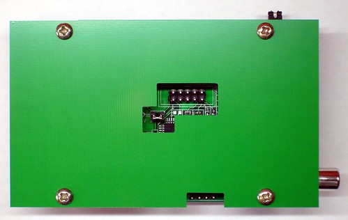
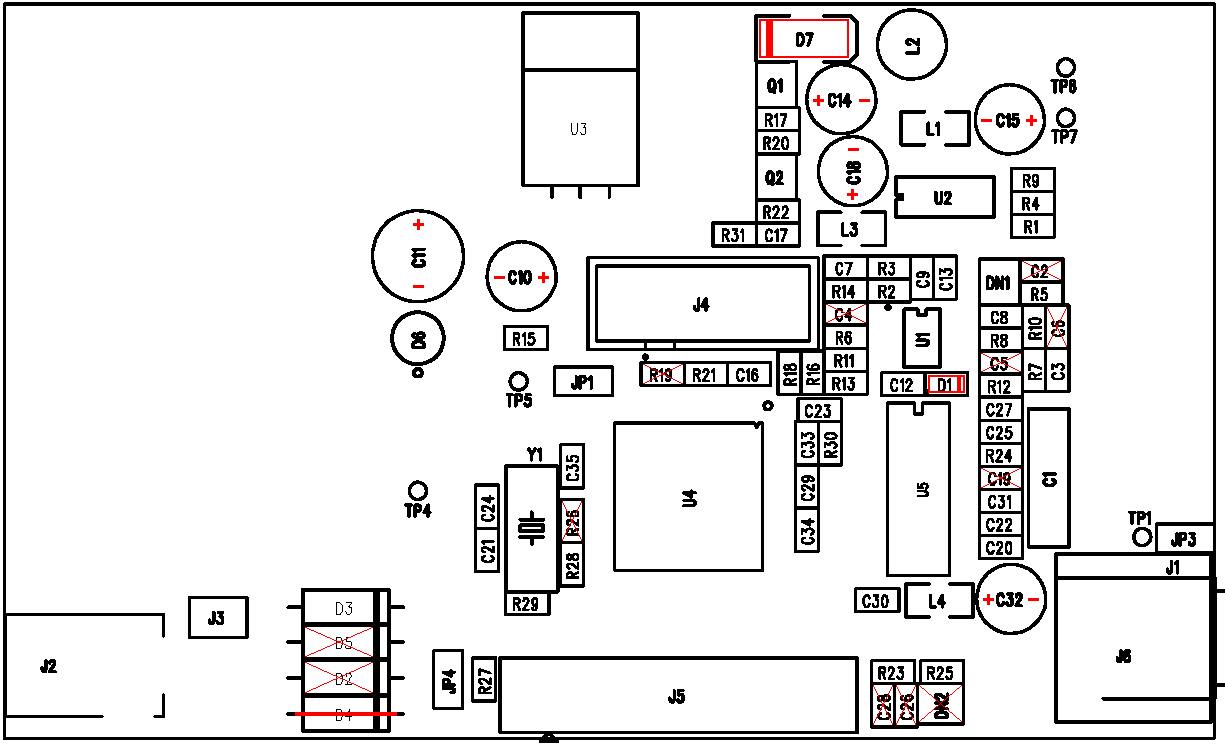
one of the photos shows D1 in good focus, the other one D7. these photos are full size, so they’re large
– some news on the scope freeze problem –
Jyetech gratiously offered to send me a FREE replacement DIY KIT
I asked whether it already comes with the latest firmware. Let’s see what happens.
As I’ve already ordered some chipquik and a new ATmega64 cpu, I’ll try to fix the scope I have right now. I’ll post most of it on my blog. If I get it fixed, I’ll post a note here as well.
A question regarding firmware update…
I built myself a Mega ISP to update the formware, downloaded the files for the 080 version from the manufacturer’s web site and ran the following .BAT file:
avrdude -P com5 -c avrisp -b 19200  -p m64 -U lfuse:w:0xAE:m -U hfuse:w:0xC0:m -U efuse:w:0xFF:m
avrdude -P com5 -c avrisp -b 19200  -p m64 -U eeprom:w:113-06201-080.eep -B 100
avrdude -P com5 -c avrisp -b 19200  -p m64 -U flash:w:113-06202-020.hex
avrdude -P com5 -c avrisp -b 19200  -p m64 -D -U flash:w:113-06201-080.hex
No matter how I set the fuse for EEPROM clear safety, I always get:
avrdude: verifying …
avrdude: verification error, first mismatch at byte 0x0000
0x13 != 0x00
avrdude: verification error; content mismatch
when trying to write the EEPROM. Everything else updates OK, however, the scope is not really working.
I managed to flash the scope with the latest firmware without avrdude errors at some point. But my scope doesn’t run stable at all. Since I did the first update it works for about a minute and then crashes. Jyetech has sent me a free replacement kit with the latest firmware. I will never ever again use an ISP programmer with it. Uploading a new firmware with the bootloader works with an FTDI cable for example (using an adapter to fix the different pin layout). When I have time I will assemble it and see how it works. I’ll also replace the cpu of my current scope as I think it is bad (after checking a few other things first).
Today I finished the replacement KIT Jyetech sent me. So far it seems to work. At first some buttons didn’t seem to work, but that somehow fixed itself. This time the LCD and the front panel were a perfect match.
If you press the push buttons too hard and hear a loud “SNAP” don’t worry. The switch is still OK. The white plastic part just cracked.
Edit:
The “old” scope draws 190mA and the new one 240mA at 9V DC. I’ve just received an email from jyetech. According to them 240mA is normal, whereas the 190mA is not. Maybe my first KIT doesn’t run properly because some component doesn’t draw/get enough juice. I’ll have to check the voltages again with that in mind. Currently brown out detection on the cpu is set to 2.7V, but I’m not sure all the other parts still work with such a low voltage. On the other hand, even if they don’t, not getting any data shouldn’t upset the cpu. The display also doesn’t flicker, so if the supply is a bit weak and drops too low, these things can’t be very long (at least not on a human based time scale). The ATMega also doesn’t reset, BOD is not triggered right now. I will change the BOD fuse to 4.0V and see if I get unexpected resets. I’ll also try to catch a bump on the 5V line with my old scope in single shot mode. The 5V regulator could be bad, limiting the scope to 190mA, so it just barely runs. Who knows. Maybe the cpu isn’t bad at all, but just easily upset