Issues with Bus Servo Driver board & SCS0009

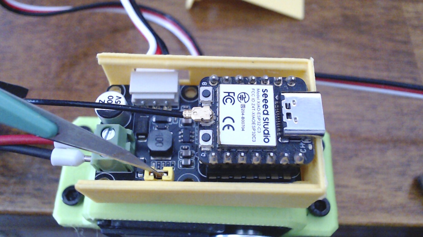
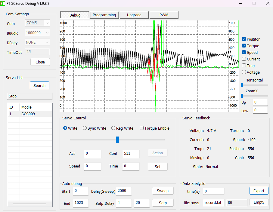
Building the Amazing Hand kit, I’ve reached the finger calibration step involving connecting the servos. Using the program FT SCServo debug 1.9.8.3, I can set individual IDs to the servos, but setting any rotation value makes the servo go completely haywire, making what appears to be random movements. Even when just connected, the monitored values are fluctuating heavily.

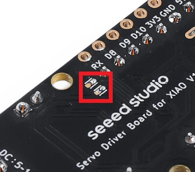
I’ve tried all connected/unconnected combinations of the jumper pins and backside pads, no difference.

“No matter, I’ll just use a xiao” I thought but that failed even more; whatever I try, I can’t even ping the servos.

Questions:

  • Why does the servo go bananas when using the FT SCServo program?
  • What’s the correct voltage? The product page for the amazing hand says 12V adapter, the servo spec says 6V but the enclosed adapter is 5V. I’ve tried a 6V I had as well but that made no difference.
  • Does the topside jumper matter at all when going the xiao/uart route?
  • What’s a minimum working program for xiao esp32c6?
  • What am I doing wrong? Is the board defect or is it me?
  • Is there a single Seeed product with worse documentation than the amazing hand? The level of “eh, you’ll figure it out” is breathtaking.

:grin:

Hi there, yea, that about sums it up out here on the bleeding edge, expect cuts I think, but would agree in general for this such a new territory for seeed, IMO. it can ONLY get better :crossed_fingers: :lying_face:

We can try, help each other until then :+1:

Did you see my video of the board and servos in action, maybe that will shed some light, I set each servo up first with the address, sounds like that may be part of it. Then the jumpers, it may be echoing all the commands and really driving the thing bonkers. Provide a picture please, let me see, what you got going on

HTH
GL :slight_smile: PJ :v:

Stay at it you will figure it out, your close. :+1:

1 Like

Thanks PJ, you are a steady island in turbulent waters :slight_smile:

Looking closer at the jumper pads, the wiki pictures and your pictures in the linked thread, I’m more confused than before. Is it supposed to be two pads to connect with one bridge, or two pairs of pads to connect with two bridges? M ine looks like the supplied photo, so I assumed the first, but now I suspect it’s the latter and the pads are already bridged?

Dont let the monkeyface fool ya..

1 Like

No risk for that. I’m a long time mostly-lurker; the contributions from monkeyface and you make the foundations of my lurkiness. I don’t have much to contribute (yet) and I can find the answers to most of my questions.

2 Likes

Hi there,

SO, LOL just when you think no one is watching…:grin: :+1:

Ok , so that looks like it TWO sets of solder Bridge pads and they are already bridged it appears in that picture. here is naked pic :face_with_hand_over_mouth:


Backside pads for version 2:
So that is the board you have… OK
Now what are the servos , can you give me the model & part # ? or picture :+1:
If the servo is being powered at the wrong voltage or from a weak/noisy supply, it can absolutely act erratic under motion. if the servo itself is a 6 V class device, feeding the wrong rail into the bus board or a sagging supply can make the position loop look insane. :face_with_spiral_eyes:

I like doing the troubleshooting walk-thru it’s a good mental exercise :smile:
something almost always shows itself…:crossed_fingers:

So because its a Half duplex communications, any echoing back “echoing commands back” is also very plausible. (that’s the jumper on top) If the driver board or USB adapter is set wrong for the SCServo half-duplex bus, commands and replies can collide. That can make:

  • position values jump around
  • motion commands decode incorrectly
  • the servo twitch or run away

If the servo has an ID but its internal center/limits are wrong for the hand linkage, sending a “rotation value” may be driving it into a hard stop or illegal range. That often looks random from the outside, but it is actually the control loop slamming against mechanics. Not in this case I 'm thinking but worth a mention.

Power supply would be the next area of suspicion… What’s the voltage and current capacity? is it a known to work unit?

I work with one servo initially also, once comms is working and I can move it , then I connect each one after setting the ID’s individual (use labels) it’s easy to get them confused " don’t ask how I know that :grin:

HTH
GL :slight_smile: PJ :v:

it’s pretty good hardware but the docs and demo’s sometimes are the achilles heal with this equipment and success to using it for makers. :+1:

I have reduced the setup to just the board connected with USB (COM5) and a single SCS0009 servo (ID 1). The pads are bridged and the top jumper is in place.
I switch between using the supplied adapter (5V 3A) and another I have on hand (6V 0.6A). As far as I can tell, the behaviour is identical for both.

This is for the 6V 0.6A after turning everything off and on again (including the host computer), then running the python scripts of FTServo_Python:

ping.py:
FTServo_Python\scscl> python .\ping.py
Succeeded to open the port
Succeeded to change the baudrate
[ID:001] ping Succeeded. SCServo model number : 1284

read.py:
The log makes it look like the servo is moving but it is actually still and quiet. You can see the same on the screenshot in my first post, with the black “position” graph fluttering when the servo is in reality doing nothing - the noisy part in the middle is when I tried to set a value and it started jittering.

FTServo_Python\scscl> python .\read.py
Succeeded to open the port
Succeeded to change the baudrate
[ID:001] PresPos:648 PresSpd:0
[ID:001] PresPos:651 PresSpd:100
[ID:001] PresPos:624 PresSpd:100
[ID:001] PresPos:624 PresSpd:-100
[ID:001] PresPos:651 PresSpd:-50
[ID:001] PresPos:624 PresSpd:-50
[ID:001] PresPos:641 PresSpd:0

wheel.py: Interestingly, PWM seems to work properly, rotating smoothly back and forth so maybe it’s just the unstable target value that’s messing things up?

read_write.py:

TServo_Python\scscl> python .\read_write.py
Succeeded to open the port
Succeeded to change the baudrate
[ID:001] PresPos:1001 PresSpd:0
[ID:001] PresPos:1001 PresSpd:0
[ID:001] PresPos:1001 PresSpd:0

(…)

[ID:001] PresPos:718 PresSpd:12000
[ID:001] PresPos:718 PresSpd:12000
[ID:001] PresPos:718 PresSpd:12000
[ID:001] PresPos:718 PresSpd:12000
[ID:001] PresPos:649 PresSpd:12000
[ID:001] PresPos:649 PresSpd:12000
[ID:001] PresPos:649 PresSpd:12000
[ID:001] PresPos:649 PresSpd:12000
[ID:001] PresPos:649 PresSpd:12000
[ID:001] PresPos:619 PresSpd:2100
[ID:001] PresPos:619 PresSpd:2100
[ID:001] PresPos:619 PresSpd:2100
[ID:001] PresPos:619 PresSpd:2100
[ID:001] PresPos:605 PresSpd:2100
[ID:001] PresPos:605 PresSpd:2100
[ID:001] PresPos:605 PresSpd:2100
[ID:001] PresPos:605 PresSpd:2100
[ID:001] PresPos:605 PresSpd:2100
[ID:001] PresPos:608 PresSpd:2100
[ID:001] PresPos:608 PresSpd:2100
[ID:001] PresPos:608 PresSpd:2100
[ID:001] PresPos:608 PresSpd:2100
[ID:001] PresPos:133 PresSpd:2100
[ID:001] PresPos:133 PresSpd:2100
[ID:001] PresPos:133 PresSpd:2100
[ID:001] PresPos:133 PresSpd:2100
[ID:001] PresPos:133 PresSpd:2100
[ID:001] PresPos:29 PresSpd:2100
[ID:001] PresPos:29 PresSpd:2100
[ID:001] PresPos:29 PresSpd:2100
[ID:001] PresPos:29 PresSpd:2100
[ID:001] PresPos:29 PresSpd:2100
[ID:001] PresPos:6 PresSpd:-30650
[ID:001] PresPos:6 PresSpd:-30650
[ID:001] PresPos:6 PresSpd:-30650
[ID:001] PresPos:6 PresSpd:-30650
[ID:001] PresPos:1 PresSpd:-30650
[ID:001] PresPos:1 PresSpd:-30650
[ID:001] PresPos:1 PresSpd:-30650
[ID:001] PresPos:1 PresSpd:-30650
[ID:001] PresPos:1 PresSpd:-30650
[ID:001] PresPos:0 PresSpd:-30650
[ServoStatus] Input voltage error!
[ID:001] PresPos:0 PresSpd:-30650
[ServoStatus] Input voltage error!
[ID:001] PresPos:0 PresSpd:-30650
[ServoStatus] Input voltage error!
[ID:001] PresPos:0 PresSpd:-30650
[ServoStatus] Input voltage error!
[ID:001] PresPos:0 PresSpd:-30650
[ID:001] PresPos:0 PresSpd:-30650
[ID:001] PresPos:0 PresSpd:-30650
[ID:001] PresPos:0 PresSpd:-30650

EDIT/ADDENDUM:

When running write.py, stopping the program or unplugging the USB does not immediately stop the servo, it keeps jittering for a second or so.

1 Like

Hi there,
So some good deep info, I see a possibility you don’t have enough :flexed_biceps: in that Power supply,
Recommended Power: Use a regulated supply capable of handling a stall current of 1.0A

  • Product Description
  • Operating Voltage:4.8V 6V
  • No Load Speed:0.125sec/60°(80RPM) 0.1sec/60°(100RPM)
  • Running Current ( no load): 120mA 150mA :backhand_index_pointing_left: :smiling_face_with_sunglasses:
  • Stall Torque (at locked): 1.89kg.cm 2.3kg.cm
  • 26.3oz.in 31.99oz.in

recommend is 6V, don’t use 5V , there are other post about Under power on these SC series. Get a Beefier 6V you be glad you did, 0.6A is just on the threshold, 1.0 amp min. will fix you up. Also

  • Does the topside jumper matter at all when going the xiao/uart route?
    You can remove it for proper operation of SC servo by the Xiao, WITH it in-place you can do both, XIAO and USB-C can send commands(not at the same time).
    DId you try a LOWER baudrate?
    Baud rate is 38400bps~1Mbps (default 1000000).

Ping ino.. what does this output ?

#include <SCServo.h>
SCSCL sc;
int TEST_ID = 3;  //Servo ID to test
void setup()
{
  Serial.begin(115200);
  Serial1.begin(1000000, SERIAL_8N1, RX, TX); // custom serial port
  sc.pSerial = &Serial1;
  while(!Serial1) {}
}

void loop()
{
  int ID = sc.Ping(TEST_ID);
  if(ID!=-1){
    Serial.print("Servo ID:");
    Serial.println(ID, DEC);
    delay(100);
  }else{
    Serial.println("Ping servo ID error!");
    delay(2000);
  }
}

   sc.pSerial = &Serial1;
   while(!Serial1) {}
 }

I like the deeper dive Waveshare has too worth a look.

HTH
GL :slight_smile: PJ :v:

here is a deeper dive..project Smart Servos | Details | Hackaday.io :+1:

Thanks PJ, I’ll get a beefier 6V adapter. First step is to check with Seeed I think, the 5V was the one supplied with the kit. I’m leaning towards asking Seeed to replace the board anyway. I know getting Seeed things working can take a bit of chewing, but this thing is solid wood. It can’t be supposed to be this difficult to get basic operations to work.

Yeah, the only working rate is 1000000, can’t ping the servo on anything lower.

I’ve run the program with D7 / D6 and the correct ID but nothing is found. The backside pads are still soldered though, don’t they have to be cleared to get the xiao (esp32c6 in this case) working?

I think that rate is WAYYY to high

Hi there,

SO , no on m in they are bridged.

@cgwaltney , not for servo’s…but for some computer com ports it IS indeed.
that’s why they have a PING for Servo’s. to test it.

HTH
GL :slight_smile: PJ :v:

Further plot developments!

TL;DR: it turned out that I was in fact investigating the Curious Case of the Two Borked Servos

I was in contact with Seeed support who suggested that I make sure it was actually the board and not the servos that was faulty. And lo! it was a good suggestion. In an interesting plot twist, it turned out that the two specific servos I had mounted on the specific finger I decided to test first, were both faulty. I can’t think of anything I have done that could have fritzed them so it’s a remarkable coincidence indeed.

I got some useful additional info about the hardware which may be useful to someone so I’ll just lore-dump here:

  1. Servo Voltage (5V vs. 6V) While the SCS0009 servo is labeled as a “6V” servo, its official operating voltage range is actually 4.0V to 7.4V. Seeed’s engineering team has rigorously tested and verified the Amazing Hand kit using the supplied 5V adapter, and it is confirmed to work reliably under normal conditions. The 5V supply provides a stable balance between performance and the longevity of the core motor.
  2. Servo Jittering Issue The “semi-random jittering” described is often related to signal interference or a specific configuration rather than a defective board. To identify the root cause, please try the following steps:
  • Isolated Test: Connect only one servo to the driver board at a time to see if the jittering persists. If it only happens when multiple servos are connected, it might be a power distribution or ID conflict issue.

  • Check Connections: Ensure all 3-pin bus cables are firmly seated. Loose signal pins in the serial chain can cause erratic behavior.

  1. Serial Bus Driver jumper pads and XIAO compatibility: The driver board is shipped in USB Mode by default, which is designed for controlling the servos directly via a PC serial port. If you intend to use a microcontroller like the XIAO ESP32C6, you will need to adjust the hardware jumpers on the back of the board to enable the correct communication path.
2 Likes