Hi there,
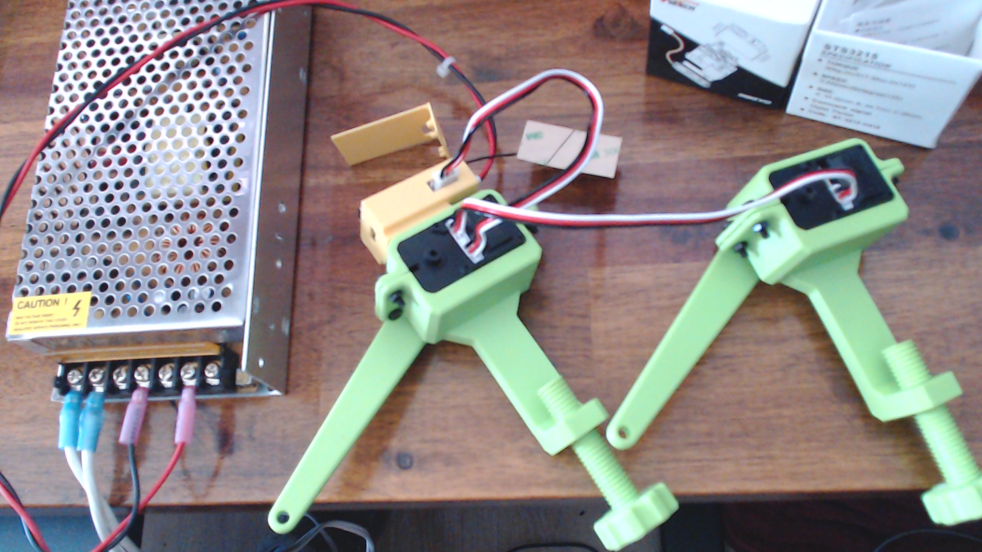
So I was able to perform all the tests and Work with both modes and two servos.
Bottom line Everything works! 
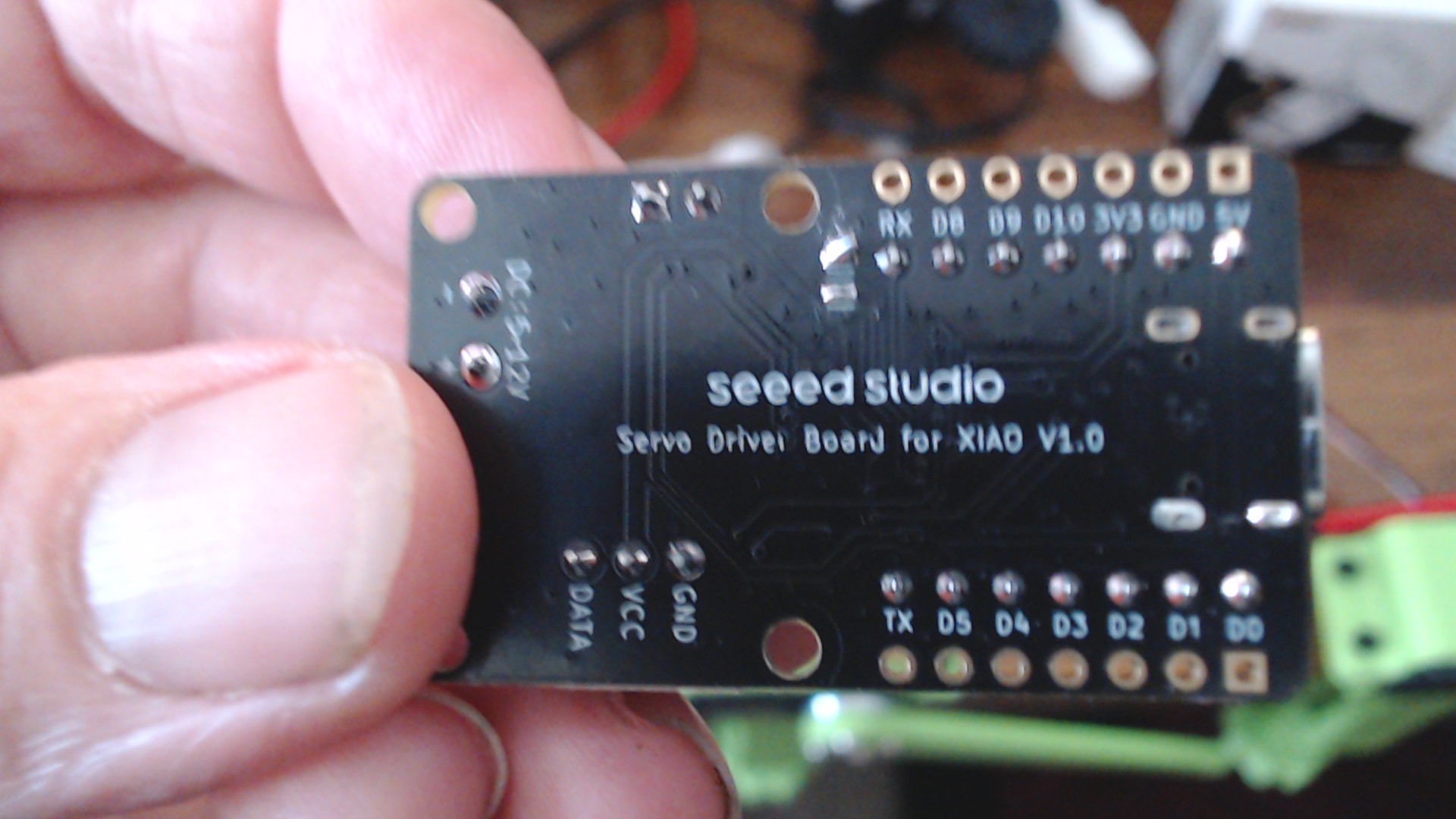
USB mode = Jumper on Top & Solder Bridges on Bottom.
Commands to move or init servos come from a USB host (terminal) by way of a Python script or dedicated control program.
Find your com port… First step.
I used a Python Script to change the ID of one of the Servos. (always power off after)
I used another to verify the ID’s
I used a third to Send position commands to each.
I used a forth “follower.py” to have one as a Master and the other as a Slave.
WORKS PERFECTLY!
Now UART Mode… 

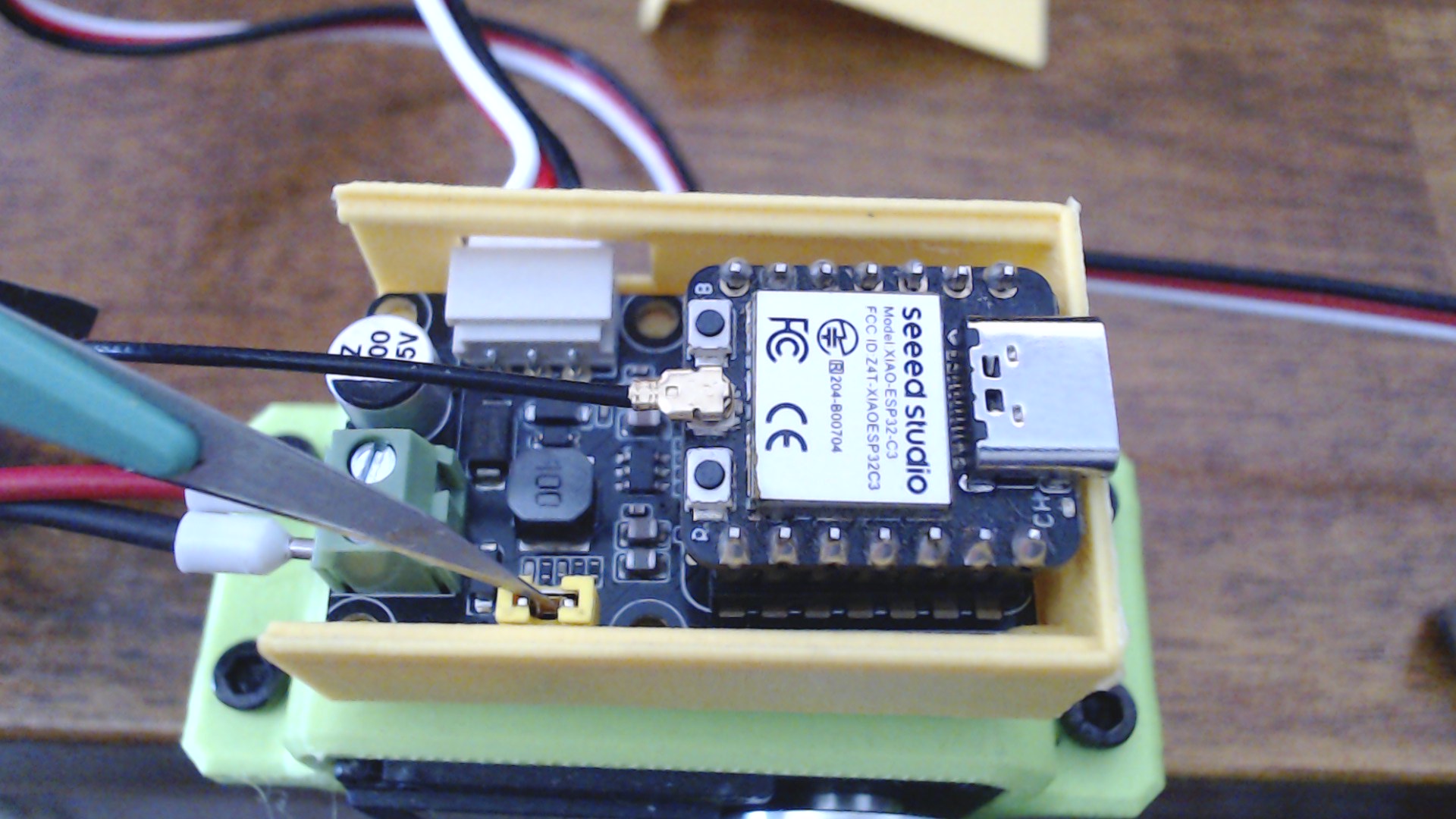
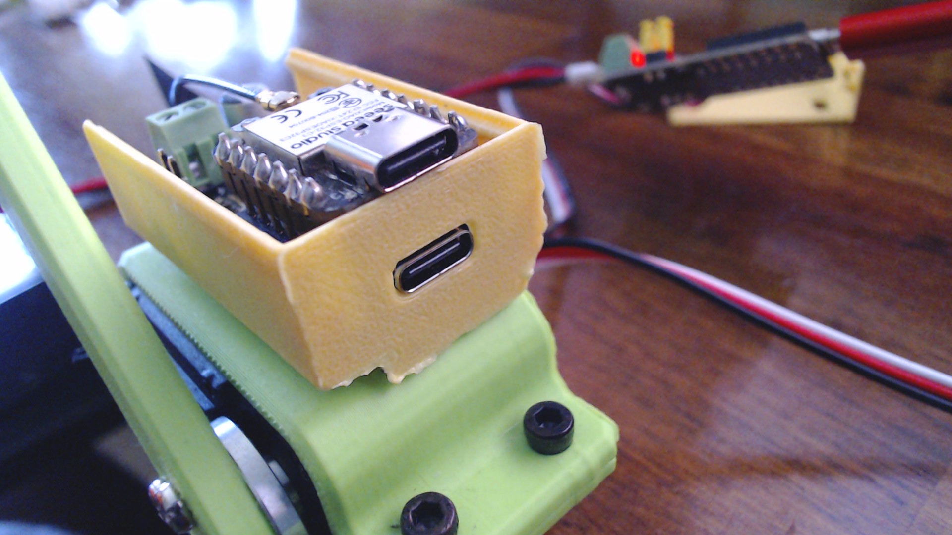
A Xiao C3 is now able to send the commands directly to the servo and the USB on the Xiao can be used to send command through the Xiao serial port to the servos as well.
This code allows just that,
Enter the command on the Serial port terminal in Arduino and move the servos directly. Truly interactive , 
Your code can move and respond to Sensor data and move the Servos, if you want to make a fine adjustment, enter it in the terminal. Or Leave it Out!
I used the SCServo Lib as instructed by the Wiki.
UART MODE - NO Solder Bridges in Place and the Jumper IS Installed on the TOP
Xiao C3 is in the slot… executing the attached Sketch, This is the Serial output
========================================
XIAO ESP32C3 UART Dual Servo Control
Rev 1.1  |  2026-03-19
Library: SCServo
Boot button self-test enabled
========================================
Pinging servos...
Servo 1: DETECTED
Servo 2: DETECTED

Reading initial positions...
Servo 1 position: 2047
Servo 2 position: 2047

Centering both servos...
Moved both -> S1: 2048  S2: 2048
Running startup demo...
Moved both -> S1: 2048  S2: 2048
Moved both -> S1: 1000  S2: 3000
Moved both -> S1: 3000  S2: 1000
Moved both -> S1: 2048  S2: 2048
Startup demo done.
========== Servo Command Help ==========
c        -> center both servos
l        -> servo1 left, servo2 right
r        -> servo1 right, servo2 left
m        -> run startup demo
t        -> run boot-button self-test demo
1 xxxx   -> move servo 1 to position xxxx
2 xxxx   -> move servo 2 to position xxxx
b xxxx   -> move both servos to position xxxx
h        -> show this help
Position range: 0 to 4095
========================================

Press the BOOT button anytime to run the self-test demo.

Moved both -> S1: 2048  S2: 2048
Moved both -> S1: 2048  S2: 2048
Running startup demo...
Moved both -> S1: 2048  S2: 2048
Moved both -> S1: 1000  S2: 3000
Moved both -> S1: 3000  S2: 1000
Moved both -> S1: 2048  S2: 2048
Startup demo done.
Boot button pressed -> running self-test demo

========================================
BOOT BUTTON SELF-TEST START
========================================
Moved both -> S1: 2048  S2: 2048
Step 1: 90 degrees one way
Moved both -> S1: 3072  S2: 3072
Step 2: 180 degrees the other way
Moved both -> S1: 1024  S2: 1024
Step 3: reverse back
Moved both -> S1: 2560  S2: 2560
Step 4: wide sweep
Moved both -> S1: 0  S2: 0
Moved both -> S1: 4095  S2: 4095
Step 5: pause
Moved both -> S1: 2048  S2: 2048
Step 6: goodbye wave
Goodbye wave...
You can see it at the end of the Video. 
Here is the code…
/*
============================================================
Project : XIAO ESP32C3 + Seeed Servo Driver Board UART Test
Board : Seeed Studio XIAO ESP32C3
Servos : STS-3215 (IDs 1 and 2)
Library : SCServo
Rev : 1.1
Date : 2026-03-19
Author : PJ Glasso & EAILLM
Features:
- UART mode servo control
- Ping servo IDs 1 and 2
- Startup motion demo
- Serial Monitor command control
- Boot button self-test / wow demo
Hardware notes:
- Board in UART mode
- Top jumper installed
- Bottom solder bridges NOT installed
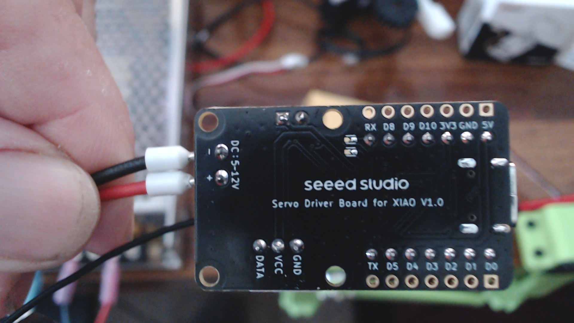
- External 12V servo power connected
- Servo IDs must already be unique (1 and 2)
Serial Monitor commands:
c -> center both servos
l -> servo1 left, servo2 right
r -> servo1 right, servo2 left
m -> middle demo move
t -> run boot-button self-test demo
1 2048 -> move servo 1 to position 2048
2 1024 -> move servo 2 to position 1024
b 1500 -> move both servos to position 1500
h -> show help
============================================================
*/
#include <SCServo.h>
SMS_STS st;
#define SERVO_SERIAL Serial0
// XIAO ESP32C3 Boot button is commonly on GPIO 9
#define BOOT_BUTTON_PIN 9
// ---------------- Servo configuration ----------------
const uint8_t SERVO1_ID = 1;
const uint8_t SERVO2_ID = 2;
const int SERVO_MIN_POS = 0;
const int SERVO_MAX_POS = 4095;
const int SERVO_CENTER = 2048;
// Motion tuning
const uint16_t MOVE_SPEED = 1500;
const uint8_t MOVE_ACC = 50;
// Button handling
bool lastButtonState = HIGH;
unsigned long lastDebounceTime = 0;
const unsigned long debounceDelay = 40;
// -----------------------------------------------------
int clampPosition(int pos) {
if (pos < SERVO_MIN_POS) return SERVO_MIN_POS;
if (pos > SERVO_MAX_POS) return SERVO_MAX_POS;
return pos;
}
void printHelp() {
Serial.println();
Serial.println("========== Servo Command Help ==========");
Serial.println("c -> center both servos");
Serial.println("l -> servo1 left, servo2 right");
Serial.println("r -> servo1 right, servo2 left");
Serial.println("m -> run startup demo");
Serial.println("t -> run boot-button self-test demo");
Serial.println("1 xxxx -> move servo 1 to position xxxx");
Serial.println("2 xxxx -> move servo 2 to position xxxx");
Serial.println("b xxxx -> move both servos to position xxxx");
Serial.println("h -> show this help");
Serial.println("Position range: 0 to 4095");
Serial.println("========================================");
Serial.println();
}
void moveServo(uint8_t id, int pos, uint16_t speed = MOVE_SPEED, uint8_t acc = MOVE_ACC) {
pos = clampPosition(pos);
st.WritePosEx(id, pos, speed, acc);
Serial.print("Moved servo ");
Serial.print(id);
Serial.print(" to ");
Serial.println(pos);
}
void moveBoth(int pos1, int pos2, uint16_t speed = MOVE_SPEED, uint8_t acc = MOVE_ACC) {
uint8_t ids[2] = {SERVO1_ID, SERVO2_ID};
s16 positions[2] = {(s16)clampPosition(pos1), (s16)clampPosition(pos2)};
u16 speeds[2] = {speed, speed};
byte accs[2] = {acc, acc};
st.SyncWritePosEx(ids, 2, positions, speeds, accs);
Serial.print("Moved both -> S1: ");
Serial.print(positions[0]);
Serial.print(" S2: ");
Serial.println(positions[1]);
}
void centerBoth() {
moveBoth(SERVO_CENTER, SERVO_CENTER);
}
void pingServo(uint8_t id) {
int result = st.Ping(id);
Serial.print("Servo ");
Serial.print(id);
Serial.print(": ");
if (result != -1) {
Serial.println("DETECTED");
} else {
Serial.println("NOT DETECTED");
}
}
void readPositions() {
int pos1 = st.ReadPos(SERVO1_ID);
int pos2 = st.ReadPos(SERVO2_ID);
Serial.print("Servo 1 position: ");
Serial.println(pos1);
Serial.print("Servo 2 position: ");
Serial.println(pos2);
}
void startupDemo() {
Serial.println("Running startup demo...");
centerBoth();
delay(1200);
moveBoth(1000, 3000);
delay(1200);
moveBoth(3000, 1000);
delay(1200);
centerBoth();
delay(1200);
Serial.println("Startup demo done.");
}
void goodbyeWave() {
Serial.println("Goodbye wave...");
int base = SERVO_CENTER;
int wave = 220;
for (int i = 0; i < 3; i++) {
moveBoth(base - wave, base - wave, 1200, 40);
delay(350);
moveBoth(base + wave, base + wave, 1200, 40);
delay(350);
}
centerBoth();
delay(500);
}
void selfTestDemo() {
Serial.println();
Serial.println("========================================");
Serial.println("BOOT BUTTON SELF-TEST START");
Serial.println("========================================");
// Start from center
centerBoth();
delay(1000);
// About 90 degrees one way
Serial.println("Step 1: 90 degrees one way");
moveBoth(3072, 3072, 1400, 50);
delay(1400);
// About 180 degrees the other way
Serial.println("Step 2: 180 degrees the other way");
moveBoth(1024, 1024, 1500, 50);
delay(1600);
// Reverse back toward center/right
Serial.println("Step 3: reverse back");
moveBoth(2560, 2560, 1400, 50);
delay(1300);
// Wider 360-ish style sweep across a large range
Serial.println("Step 4: wide sweep");
moveBoth(0, 0, 1700, 60);
delay(1800);
moveBoth(4095, 4095, 1700, 60);
delay(2200);
// Pause
Serial.println("Step 5: pause");
centerBoth();
delay(1200);
// Small goodbye wave
Serial.println("Step 6: goodbye wave");
goodbyeWave();
Serial.println("SELF-TEST COMPLETE");
Serial.println("========================================");
Serial.println();
}
void processSerialCommand() {
if (!Serial.available()) return;
String line = Serial.readStringUntil('\n');
line.trim();
if (line.length() == 0) return;
if (line.equalsIgnoreCase("h")) {
printHelp();
return;
}
if (line.equalsIgnoreCase("c")) {
centerBoth();
return;
}
if (line.equalsIgnoreCase("l")) {
moveBoth(1000, 3000);
return;
}
if (line.equalsIgnoreCase("r")) {
moveBoth(3000, 1000);
return;
}
if (line.equalsIgnoreCase("m")) {
startupDemo();
return;
}
if (line.equalsIgnoreCase("t")) {
selfTestDemo();
return;
}
char cmd = line.charAt(0);
int spaceIndex = line.indexOf(' ');
if (spaceIndex < 0) {
Serial.println("Invalid command. Type 'h' for help.");
return;
}
String valueStr = line.substring(spaceIndex + 1);
valueStr.trim();
int pos = clampPosition(valueStr.toInt());
switch (cmd) {
case '1':
moveServo(SERVO1_ID, pos);
break;
case '2':
moveServo(SERVO2_ID, pos);
break;
case 'b':
case 'B':
moveBoth(pos, pos);
break;
default:
Serial.println("Unknown command. Type 'h' for help.");
break;
}
}
void checkBootButton() {
bool reading = digitalRead(BOOT_BUTTON_PIN);
if (reading != lastButtonState) {
lastDebounceTime = millis();
}
if ((millis() - lastDebounceTime) > debounceDelay) {
static bool buttonHandled = false;
// Active low button press
if (reading == LOW && !buttonHandled) {
Serial.println("Boot button pressed -> running self-test demo");
selfTestDemo();
buttonHandled = true;
}
if (reading == HIGH) {
buttonHandled = false;
}
}
lastButtonState = reading;
}
void setup() {
pinMode(BOOT_BUTTON_PIN, INPUT_PULLUP);
Serial.begin(115200);
delay(2000);
Serial.println();
Serial.println("========================================");
Serial.println("XIAO ESP32C3 UART Dual Servo Control");
Serial.println("Rev 1.1 | 2026-03-19");
Serial.println("Library: SCServo");
Serial.println("Boot button self-test enabled");
Serial.println("========================================");
SERVO_SERIAL.begin(1000000);
st.pSerial = &SERVO_SERIAL;
delay(200);
Serial.println("Pinging servos...");
pingServo(SERVO1_ID);
pingServo(SERVO2_ID);
Serial.println();
Serial.println("Reading initial positions...");
readPositions();
Serial.println();
Serial.println("Centering both servos...");
centerBoth();
delay(1200);
startupDemo();
printHelp();
Serial.println("Press the BOOT button anytime to run the self-test demo.");
}
void loop() {
processSerialCommand();
checkBootButton();
}
Remove the USB cable , and Press the boot button for a selftest hands-Free.
GL
HTH
AMA
PJ