Is the LM20A's nPM1300 Unbeatable? Comparing the Current Consumption of the 52840, L15, and LM20A in a Sample Application

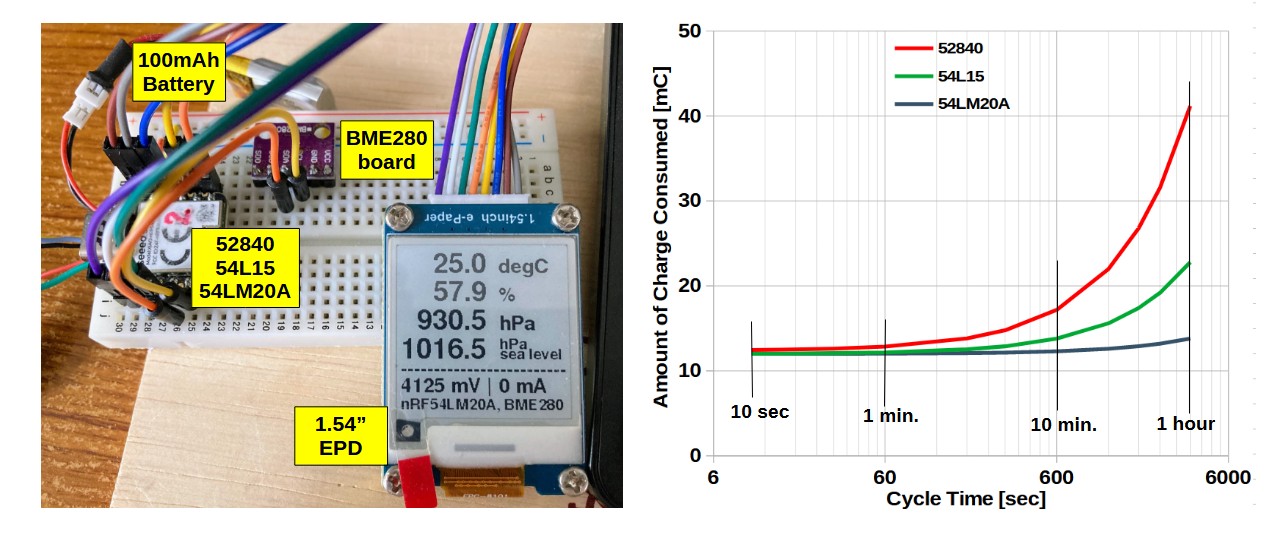
Using the Hibernate mode of the nPM1300 chip built into the XIAO_nRF54LM20A results in a sleep current of 0.5 μA or less, which is far lower than that of other boards based on the nRF54L15 and nRF52840. To see what difference this makes in a real-world application, I tested it using a simple weather monitor built with a BME280 and a Waveshare 1.54-inch EPD.

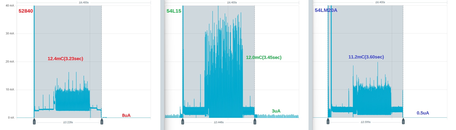
This application alternates between a “Working” period—during which the device wakes up, takes measurements, and displays the results—and a “Sleep” period, repeating this cycle at a fixed interval.

While the total charge consumed during the Working period is nearly identical across all three boards at approximately 12 mC (3.5 seconds), the average current during the Sleep period varies significantly: 0.5 μA, 3 μA, and 8 μA for the nRF54LM20A, nRF54L15, and nRF52840, respectively.

The graph below compares the total charge consumed over operating cycles ranging from 10 seconds to 1 hour.

The LM20A’s advantage becomes particularly significant when the operating cycle is around 10 minutes or longer. In applications where charge consumption during the active period is high and the sleep period is short, however, the benefit of the nPM1300’s extremely low Hibernate current is relatively limited.

Here is the sketch used in the experiment. For the LM20A and L15 BSPs, I used nRF54L15 Boards 1.0.17, while for the 52840 BSP, I used Seeed nRF52 Boards 1.1.13. For the EPD, I used Waveshare’s epd1in5_V2 library, which supports fast redraws.

nRF5254_WeatherMonitor.zip (138.7 KB)

WM_Video.zip (3.9 MB)

In the next installment, I plan to investigate the issue of high cold-boot overhead in applications where the charge consumed during the “Working” period is relatively small.

:grin: The Power Ninja puts on a clinic… :ninja:

A+

Another fantastic write-up! Your presentation and side-by-side data make these comparisons so clear to read, and thank you for consistently raising the bar with your benchmarks on the forum.

Looking at the 12 mC active window (3.5 seconds) across the three boards, I suspect there is a lot of hidden potential still left on the table that might tip the scales even further in the LM20A’s favor.

A couple of observations and hopefully the new version has the PMIC right, this one does come up a TAD short, your post makes it clear. albeit not the end of the world , they (Seeedineers where 2 traces and a via) away IMHO :bow: from total success on this part.

No Dynamic Rail Gating: Because the 3.3V header (Pin 12) is not gated by the PMIC, the MCU cannot dynamically shed peripheral bias current during the active cycle. (they are adding it to another pin instead maybe, He claims so to maintain backwards compatibility, which makes no sense to me, it was a short coming in the original IMHO ) :bow:

Cold-Boot & Bus Re-Init Delays: Every wake cycle boots cold, re-enumerating I2C/SPI buses and clock trees, and running multi-millisecond display controller power-up delays.

Right now, the 3.3 V header (Pin 12) remains energized during sleep. As long as external peripherals (the BME280 and Waveshare EPD) stay biased on that rail, they can either draw continuous quiescent current or cause back-feeding into the MCU I/O pins via protection diodes unless those lines are meticulously parked.
I’ve actually discussed this directly with Seeed as a suggested design change for future revisions: the interconnect routing leaves some money on the table because the PMIC’s unused output/load switches (or a PMIC GPIO controlling the external regulator’s enable line) really should gate the 3.3 V pin. They are aware that the nPM1300 is only partially utilized here and that properly gating Pin 12 would yield noticeably better overall sleep performance without needing off-board switches.

Shrinking that active window down from 12 mC to 2–3 mC will shift your break-even curve dramatically—allowing the nPM1300’s sub-microamp hibernate to show its real dominance at 1- to 2-minute update intervals rather than needing 10+ minutes.

Looking forward to your next installment on the cold-boot overhead!

HTH
GL :slight_smile: PJ :v:

Running the numbers:
TRY IT :grin:

In a 10-second loop, the sleep phase accounts for less than 0.4% of the total energy consumed. The nPM1300’s ultra-low sleep current provides an almost imperceptible 0.4% improvement in overall battery life.

further…

at Over an hour, sleep charge dominates. The LM20A draws roughly one-third the energy of the 52840, extending battery life nearly threefold.

:exploding_head:

Hi PJ, thanks for your comment.

Here are a couple of additional points from me:

  1. When running on battery power, no 3.3V is output during hibernation mode, so there is no power consumption by external devices.
  2. The main breakdown of the 12 mC consumed during the active period is as follows: 4 mC for cold boot, re-initialization of the BME280 and EPD, and 8 mC for measurement and rendering—with the majority attributable to the EPD. This application intentionally uses an example where external devices consume a large amount of charge.

Hi @msfujino, NO, thank YOU :index_pointing_at_the_viewer: :grin:

Thanks for that breakdown, that actually confirms what I was suspecting and makes your upcoming installment on cold-boot overhead all the more interesting! :+1:

That 4 mC cold-boot tax is a full third (33%) of the entire active charge budget. Because the 3.3V rail completely cuts out in battery hibernation, the SSD1681 and BME280 lose their register state and volatile buffers, forcing the MCU to pay that heavy penalty to re-enumerate buses and clock trees, wait out oscillator delays, and push full init command sequences every cycle.

If the architecture allowed for an independent low-leakage rail or warm-wake retention state where the display controller’s partial-refresh context survived, that 4 mC overhead would practically vanish.

It also illustrates why the nPM1300’s sub-microamp hibernate takes so long to separate itself from the 52840 on shorter intervals: when a fixed 12 mC active hump (with 4 mC of re-init overhead) dominates the cycle, the sleep savings are fighting an uphill battle against Amdahl’s Law. When 12 mC is burned on active work, the difference between 0.5 µA and 8 µA sleep current is negligible until you sleep for 10–15+ minutes.

Really looking forward to seeing how you tackle the cold-boot optimization in the next post!

  1. Because Pin 12 drops power entirely on battery sleep, the external display controller and sensor lose all internal register state and volatile frame buffers.
  2. Upon wake, the MCU has no choice but to execute a heavy, blocking power-up sequence, oscillator stabilization delay, and full command-table init on the SSD1681.
  3. :crossed_fingers: If the PMIC had an independently controlled rail or gated load switch dedicated to external accessories while maintaining internal state, the system wouldn’t have to suffer that cold hardware penalty every loop. :+1:
Analyzing Boot Overhead in Low-Power Applications

In my previous post, I compared the power consumption of the XIAO_nRF52840, XIAO_nRF54L15, and XIAO_nRF54LM20A (hereafter referred to as the 52840, L15, and LM20A, respectively), using a Weather Monitor as an example. Since the charge consumed during the Working period was relatively large in that application, the overhead caused by rebooting was not particularly noticeable.

This time, I analyzed an application in which the charge consumed during the actual operation period is small, making reboot overhead a dominant part of the total charge consumption. The application wakes up at a fixed cycle interval, takes a measurement, and then transmits five advertising packets at 40 ms intervals before entering sleep mode.

nRF5254_WeatherMonitor_Adv.zip (55.9 KB)

Boot Overhead and Cycle Time

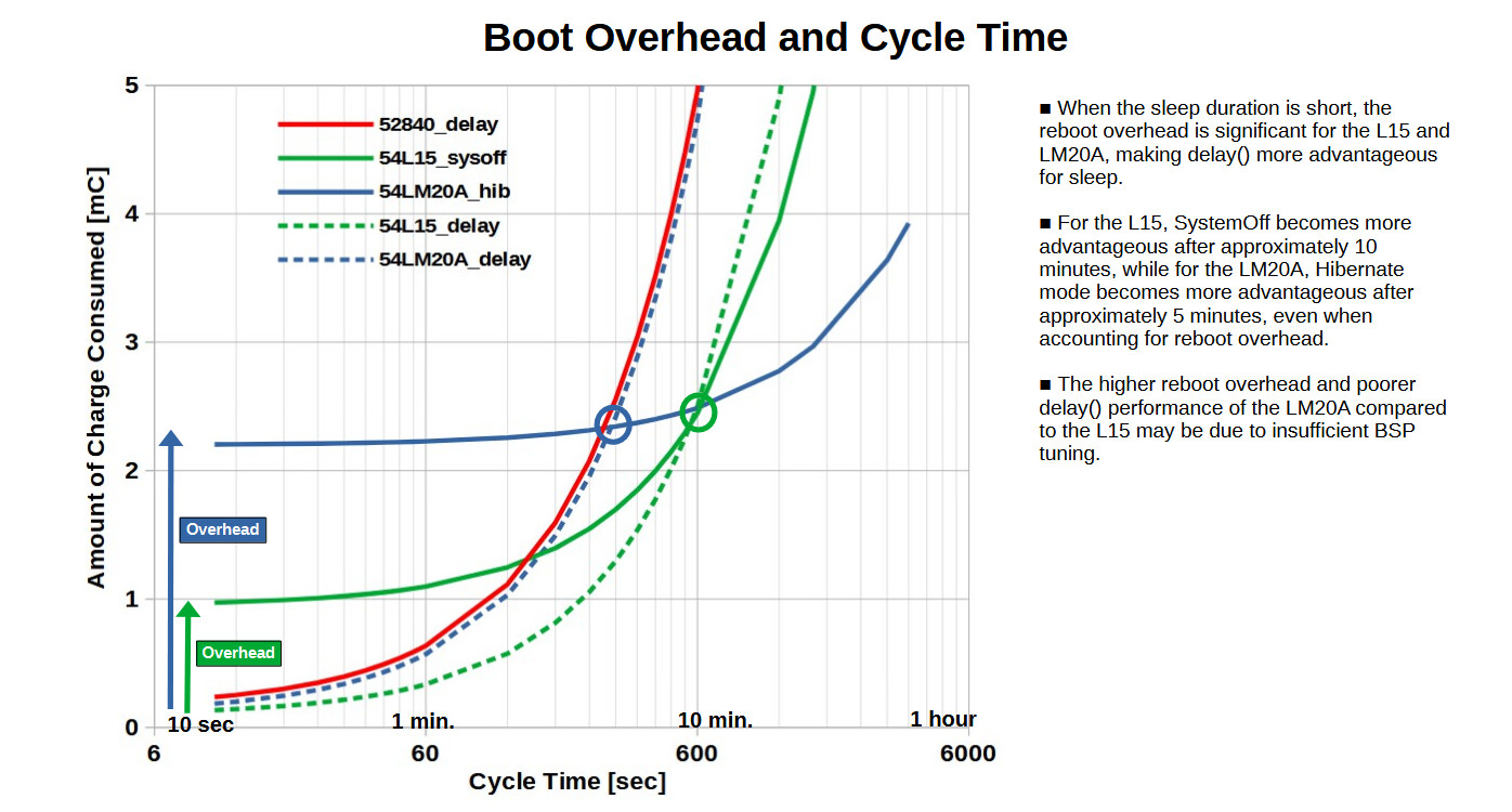
This graph compares the reboot overhead and total charge consumption for different cycle times.
The solid lines show the total charge consumption when using delay mode on the 52840, SystemOff mode on the L15, and Hibernate mode on the LM20A. The dashed lines show the total charge consumption when both the L15 and LM20A use delay mode for sleep without rebooting.

At short cycle times, the charge consumed by rebooting becomes dominant on the L15 and LM20A, making these modes less advantageous than delay mode. As indicated by the circles in the graph, the crossover point is approximately 10 minutes for the L15 and 5 minutes for the LM20A. Beyond these cycle times, using SystemOff or Hibernate mode becomes more advantageous, even when the reboot overhead is taken into account.

Comparing the three boards, there is little difference in total charge consumption up to 1 minute. However, the L15 using delay mode shows the best performance up to 10 minutes, while the LM20A using Hibernate mode becomes overwhelmingly advantageous beyond 10 minutes.

Factors Contributing to the Overhead

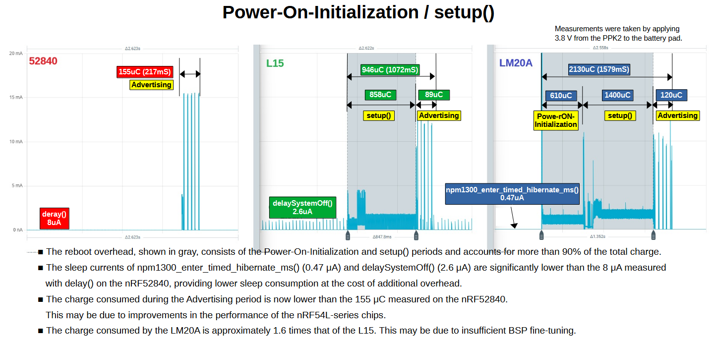
This figure breaks down the reboot overhead for the L15 and LM20A. The gray areas represent the Power-On-Initialization and setup() periods. These periods account for more than 90% of the total charge consumed, as shown in the figure.

On the LM20A, Hibernate mode reduces the sleep current to approximately 0.47 μA. On the other hand, the L15 consumes approximately 2.6 μA in SystemOff mode. For both boards, the charge consumed during the Advertising period is lower than the 155 μC measured on the 52840. This may be due to improvements in the performance of the nRF54L-series chips.

In addition, in this measurement, the charge consumed during setup() on the LM20A was approximately 1.6 times that of the L15. This may be due to insufficient BSP tuning.

Appendix: Advertising and delay Mode Current

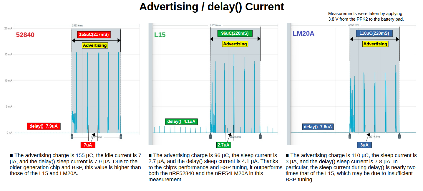
This figure shows the charge consumed during the Advertising period and the sleep current during the delay mode sleep period.
On the 52840, the five advertising transmissions consume approximately 155 μC, and the sleep current is approximately 7.9 μA, the idle current is 7 uA. On the L15, advertising consumes approximately 96 μC, and the sleep current is approximately 4.1 μA, the idle current is 2.7 uA. Using SystemOff mode reduces the sleep current further to approximately 2.6 μA. On the LM20A, advertising consumes approximately 110 μC, and the sleep current is approximately 7.8 μA, the idle current is 3 uA. Using the nPM1300’s Hibernate mode reduces the sleep current is approximately 0.47 μA.

In particular, since the sleep current of the LM20A, which uses the same architecture, is approximately twice that of the L15, further BSP improvements would be desirable.

Conclusion

This experiment demonstrates that the benefits of Hibernate mode’s extremely low sleep current depend heavily on the operating conditions of the application.

In applications with long sleep periods, the low sleep current of the L15, and especially the LM20A, provides greater benefits. On the other hand, when the charge consumed during the active period is small, reboot overhead can dominate the total charge consumption. In such cases, sleeping in delay mode without rebooting may be more advantageous.

Hi there,
Spot on as always, @msfujino! You have a knack for cutting right to the heart of what real-world low-power engineering actually looks like beyond the datasheet claims.
:ninja:
A few thoughts and observations to add to your excellent breakdown:

  • The Reboot Penalty is Real: Identifying that 5-minute (LM20A) and 10-minute (L15) crossover point is pure gold for anyone architecting periodic sensor nodes. People often forget that dragging an MCU through cold initialization and bloated setup() cycles burns far more Coulombs than letting the SoC idle in RAM-retentive delay sleep when broadcast intervals are tight.

  • BSP Tuning & Init Overhead: The fact that setup() on the LM20A draws ~1.6x the charge of the L15 reinforces what many of us suspect: the early BSP/SDK startup routine likely leaves peripheral clocks running or defaults PMIC rails/LDOs on before user code even touches them. Trimming unneeded peripheral init in SystemInit() could shift that crossover point significantly to the left.

  • PMIC Rail Control: It would be interesting to see how much of that LM20A setup delta is tied to powering onboard peripherals during boot. Gating external rails/LDOs strictly via the nPM1300 early in the boot sequence might recover a decent chunk of that initial power-on charge.

Top-tier analysis and clear presentation as always. Looking forward to seeing where Seeed takes the BSP optimizations once they digest this data! :face_with_monocle:

Best,

GL :slight_smile: PJ:v:

I’d like to request some improvements for the next version of nrf54-arduino-core.

Also, once XIAO_nRF54LM20A is officially supported in NCS, I’d like to test it out in Zephyr to see what kind of results I get.

Hi there,

100% agree, I want them to do the proper BSP on the 54L15 ASAP , start there, learn and then improve what they have for LM20A, I’m looking into making some suggestions on the BSP to whom I’m no sure, but I’ll ping you when I have something concrete. :+1:

HTH
GL :slight_smile: PJ :v:

Key Areas for BSP Optimization

  • Eager vs. Lazy Peripheral Clocks (UART/CDC & Timers):

    • The Problem: Many BSP startup routines initialize USB/CDC-ACM, logging UART, ADC calibration, or hardware timers immediately in SystemInit() or pre-main(), running their clocks whether the sketch uses them or not.

    • The Fix: Move peripheral clock gating to lazy initialization (instantiate clocks only when Serial.begin(), Wire.begin(), or analog reads are explicitly called).

  • Unused GPIO Floating States:

    • The Problem: Pins left unconfigured or floating at boot create parasitic shoot-through current in input buffer logic gates.

    • The Fix: Ensure the core sets all unrouted or non-connected pad configurations to high-impedance / disconnected (PIN_CNF[n].INPUT = Disconnect / PULL = None) during startup.

  • nPM1300 Default Power Rails & Buck Transition Delays:

    • The Problem: On the LM20A, the nPM1300 may power up with default buck/LDO configurations, battery charge-state engines, or active LED drivers running prior to user configuration. Furthermore, if the MCU’s internal DC/DC converter isn’t commanded on immediately during startup, it defaults to running the inefficient internal LDO regulator through the entire boot cycle.

    • The Fix: Ensure early boot code commands the nPM1300 to keep auxiliary output rails (like the 3.3V header rail) disabled until specifically requested, and verify the core switches the nRF54 core regulator to DC/DC mode right at reset.

  • SRAM Retention Masking in Deep Sleep:

    • The Problem: In SystemOff or partial low-power states, retaining all SRAM banks consumes unnecessary quiescent current.

    • The Fix: Provide simple API flags in the BSP power management wrapper (e.g., setRetainedRamBlocks()) so developers only power the minimum RAM sectors needed for warm-boot state or context preservation.

  • Non-Blocking Sleep Hooks in delay():

    • The Problem: In standard Arduino implementations, delay() or wait-loops for crystal/oscillator stabilization (HFXO/LFCLK) often sit in active spin loops rather than dropping into __WFE() (Wait For Event) or Zephyr’s tickless idle.

    • The Fix: Route delay() through tickless low-power sleep and ensure crystal stabilization waits suspend the CPU.

To build on that, if Seeed wants to trim that setup() tax and narrow the gap between the LM20A and L15, here are a few concrete areas in the BSP/Core worth profiling:

  1. Lazy Clock & Bus Gating: Make sure SystemInit() isn’t aggressively powering on UART/CDC, SPI, or I2C peripheral clocks until user code explicitly calls .begin(). Keeping peripherals completely dark until invoked would instantly shave charge off the pre-main() window.

  2. Early DC/DC & PMIC Rail Defaults: Confirm the core enables the chip’s internal DC/DC regulator early in startup rather than idling on the higher-consumption internal LDO. For the LM20A specifically, ensuring the nPM1300 keeps external power rails/LDOs strictly gated off by default at boot prevents unneeded current draw into attached components.

  3. GPIO Floating Pad Leakage: Verify that all unassigned pins default to disconnected (PIN_CNF.INPUT = Disconnect) in the pin mux table at startup so they aren’t leaking microamps through floating inputs.

  4. Tickless Idle in delay() & Stabilization Loops: Ensure oscillator warmup (HFXO/LFCLK) and delay routines drop straight into __WFE() / low-power retention rather than spinning the CPU core.

Tackling even two of those would significantly reduce the reboot penalty and push that Hibernate crossover time much further down!

GL :slight_smile: PJ :v:

I have requested an investigation into BSP:nrf54-arduino-core here.

I plan to wait until the LM20A is officially supported by NCS before trying it out with Zephyr. As it stands, I’m having trouble compiling it.

Hi there,

SO they are looking into the BSP for the new XIao’s, I added you to that DISCORD thread and forwarded the contact. They have performed some test using PLIO, so we need to be sure it’s reproducible for one, and that it addresses any other issue.

HTH
GL :slight_smile: PJ :v:


"
@PJGlasso ​ Thank you for the detailed analysis and for flagging this — feedback like yours helps us make the board better.​ ​ We ran our wiki low-power sample on a 20A board through the PlatformIO toolchain and measured with a PPK2: the reboot crossover threshold comes out to ~4 seconds. The “>5 min” behavior you saw on the Arduino core does not reproduce on the Zephyr path — and since NCS is also Zephyr-based, we expect the same holds there. The reason is visible in the trace: our Zephyr boot burst is only ~20 ms with no long mA-level plateau, so the boot charge stays in the tens of µC.​ ​ Measurement summary (formula, values, calculation) and PPK2 screenshots attached. Happy to compare traces anytime — thanks again for the report "
:grin: :+1:

Hi PJ,

It took quite a bit of effort, but I’ve finally managed to compile the L15 project using ncs 3.2.4. I’ll be moving on to the LM20A next.
I’m currently rewriting the L15 Arduino Core sketch for ncs Zephyr. I’ll post the results of the current waveform comparison here as soon as they’re available.

In a previous post (Post #5), I compared the charge consumption of the XIAO_nRF52840, 54L15, and 54LM20A for applications with low operating charge consumption, where the overhead from the boot process accounts for a significant portion of the total charge consumption.

At that time, because the charge consumption during setup() was extremely high in the nrf54-arduino-core (hereinafter referred to as Arduino Core) environment, software optimization through BSP tuning was highly anticipated. Furthermore, comparative testing in the nRF Connect SDK (hereinafter referred to as NCS) environment had not yet been conducted.

Since then, Arduino Core v1.0.19 has been released, successfully halving the charge consumed during boot initialization and setup(). (Thanks, @Loren_Bufanu) I also conducted similar measurements in the previously untested NCS environment and obtained data nearly identical to that of the Arduino Core environment. Note that the XIAO_nRF52840 was excluded from this evaluation because it had no new updates or improvements relevant to this comparison.

Build and Testing Environment

nrf54-arduino-core (Arduino IDE 2.3.10)
  XIAO_nRF54L15   BSP: 1.0.19, Board: XIAO nRF54L15 / Sense
  XIAO_nRF54LM20A BSP: 1.0.19, Board: XIAO nRF54LM20A
nRF Connect SDK (Visual Studio Code 1.140.0)
  XIAO_nRF54L15   NCS & Toolchain: v3.2.4, Target: xiao_nrf54l15/nrf54l15/cpuapp
  XIAO_nRF54LM20A NCS & Toolchain: v3.3.0, Target: xiao_nrf54lm20a/nrf54lm20a/cpuapp
                  Board library: platform-seeedboards Release 1.0.0

Note: To prevent build errors during v3.3.0 environment setup, unnecessary files and folders unrelated to XIAO_nRF54 were removed from the platform- seeedboards/zephyr/ directory.

The sketches and projects used in the experiment can be found here.
POST_Projects.zip (698.1 KB)

Measurement Conditions
Measurements were taken with a 3.8 V supply from the PPK2 connected to the battery pads.

Sleep Mode APIs Used

Delay mode:      Arduino Core: `delay()` / NCS: `k_msleep()`
System OFF mode: Arduino Core: `delaySystemOffNoRetention()` / NCS: `sys_poweroff()`
Hibernate mode:  Arduino Core: `npm1300_enter_timed_hibernate_ms()` / NCS: `mfd_npm13xx_hibernate()`

Boot Overhead

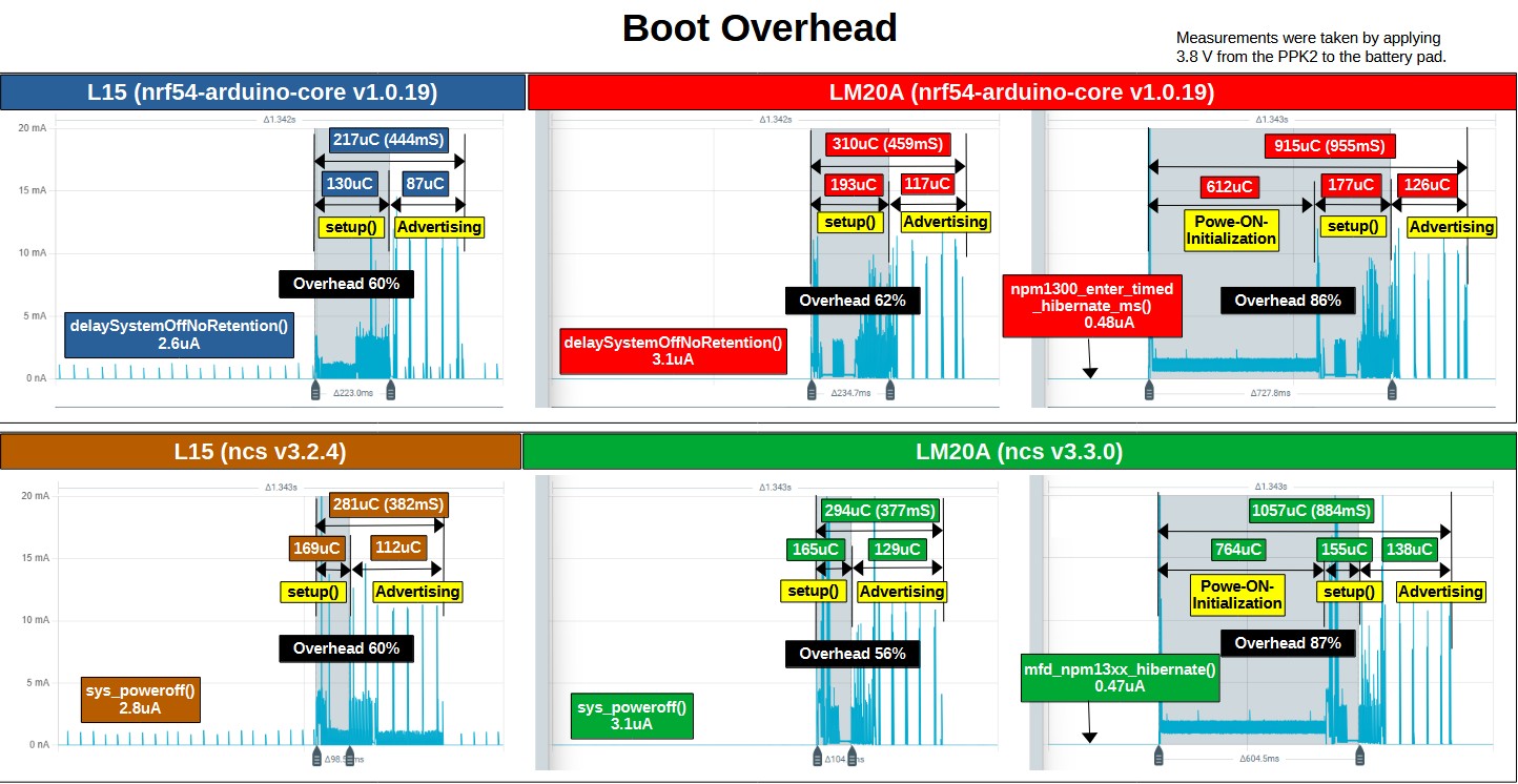
The figure (Boot Overhead) illustrates the breakdown of the current waveforms during wake-up and transmission in System OFF mode and Hibernate mode, both of which require a system boot.

Of the total charge consumed during the active period, boot overhead (initialization and setup) accounts for approximately 56–62% in System OFF mode and more than 85% in Hibernate mode. The sleep current (average current during the sleep interval) was measured at approximately 3 μA for both the L15 and LM20A in System OFF mode. Furthermore, Hibernate mode on the LM20A, utilizing the nPM1300, achieved an ultra-low sleep current of 0.5 μA or less.

These consumption ratios remained nearly identical regardless of whether the project was built using Arduino Core or NCS, indicating that the build environment has no significant impact on power efficiency. The issue of high charge consumption during setup(), which was a bottleneck in the previous evaluation, has been fully resolved in the latest Arduino Core v1.0.19, bringing it down to a level comparable to NCS.

Cycle Time and Amount of Charge Consumed

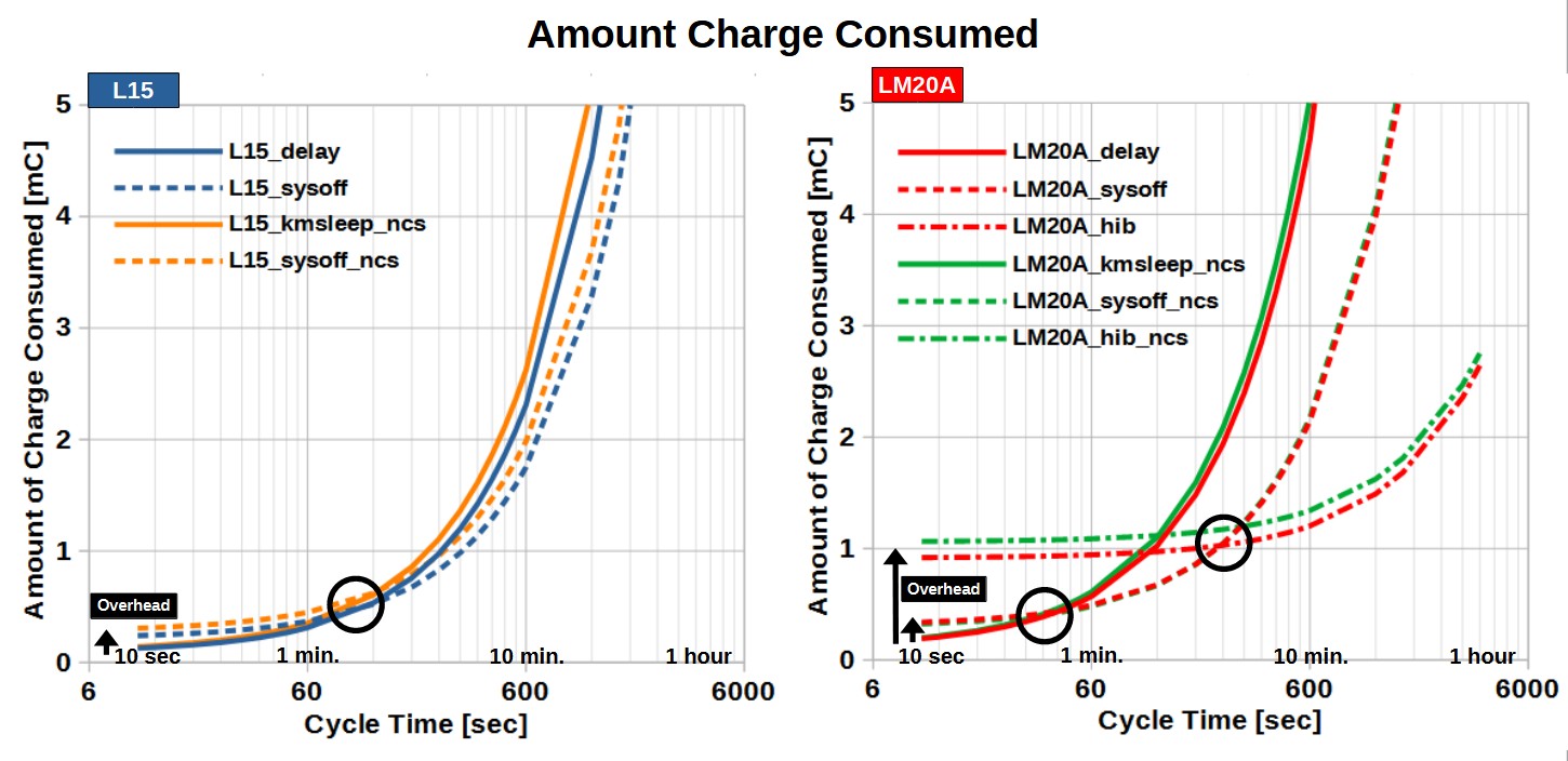
The figure (Amount of Charge Consumed) plots the total charge consumption as a function of the cycle time (transmission interval). The crossover points, where the relative advantages of each mode change, are marked with circles (◯).

Because the setup overhead was halved, these crossover points have shifted significantly compared with the previous results, where the crossover points were approximately 10 minutes for the L15 and 5 minutes for the LM20A.

minute or less (Short Cycle)
Although the boot overhead has been reduced, utilizing Delay mode during sleep remains the most efficient choice for such short intervals.

1 to 5 minutes (Mid Cycle)
Once the cycle time exceeds 1 minute (60 seconds), the sleep current becomes the dominant factor. For both the L15 and LM20A, System OFF mode reduces total charge consumption more effectively than Delay mode, making System OFF more efficient.

5 minutes and beyond (Long Cycle)
Furthermore, when the cycle time exceeds 5 minutes, Hibernate mode on the LM20A, which reduces sleep current to 0.5 μA or less, completely offsets the penalty of its high initialization overhead, making it overwhelmingly superior.

Summary

The experimental results demonstrated no significant differences between the Arduino Core and NCS build environments.

For this specific application, the criteria for selecting the optimal sleep mode based on the cycle time are as follows:

1 minute or less: Delay mode
1 to 5 minutes: System OFF mode
5 minutes or more: Hibernate mode

The actual crossover points and charge consumption values can vary significantly depending on the application. However, the overall trends should remain valid, and I hope these results will provide a useful reference for your own hardware and software design.