Hey makers,
What features do you want to see covered?
The majority of the samples are now tested, and should work with no configuration after copying the board definition to the correct folder, and adding the sample folder to nrf connect as a existing application.
5 of the listed samples are fully tested and working.
I’ll be working on updating this further over the weeknd.
The point of these samples is to be able to load them with as little user configuration required as possible to give people new to the nrf54l15 a working starting point.
To use them:
Install nrf connect, and have it install sdk 3.1.1 & the toolchain for it.
copy the seeed board defs into the zephyr sdk folder
select add application in NRF connect, and select the sample folder for the sample you want
create a build configuration selecting xiao_nrf54l15_nrf54l15_cpuapp & choose “use sysbuild”
leave all board def & prj,conf stuff blank, it’s auto filled by the xiao_ named files in the boards subfolder of each sample.
Copying the seeed board contents of the sdk folder folder:
grab this git repo, either as a zip or with git, then
from inside the repo copy the folder zephyr/boards/arm/*
to the location you installed the 3.1.1 sdk to in the first step, example:
C:\yourSDKpath\3.1.1\zephyr\boards\arm*
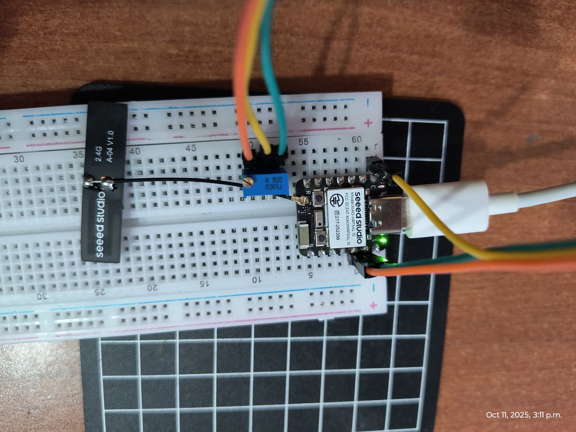
New tested & Updated ADC sample!
Uses the xiao nrf54l15’s onboard user led to show a potentiometer value via the led blink rate. uses an intuitive inverted scale, where more light = more volts (3300ms delay = 0v, no delay = full 3.3v)
I would have used PWM, but the pin the user led is attached to is not hardware pwm capable.
[00:59:30.421,749] <inf> adc_blink_example: ADC Raw = 3761 (3305 mV) Blink Delay = 25 ms
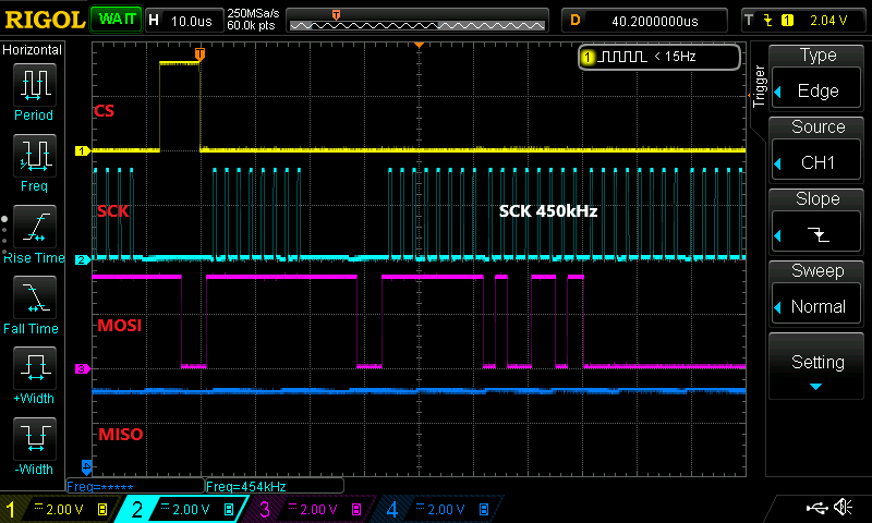
The majority of the samples in this set have now been tested, and working. I found a work-around for the SD-card reader on the xiao expansion base using the zephyr spi bitbang driver.
The Sd card sample will write testing.txt with the contents “Hello from Xiao nRF54l15” in it to the inserted fat formatted sd card.
I’m not sure why the regular spi driver refuses to initailize with the SDcard reader on the xiao expansion base, but this works so, it’s at least access to sdhc!
I tested the SD card sample and confirmed it works. Thank you.
Since bit-banging is used, the SCK clock is only 450kHz. Can the clock frequency be increased? Is there any possibility of using hardware SPI?
I’m sure it’s possible to get the hardware SPI working, but I’m not sure why it doesn’t work now. It gets really upset during initialization about… I’m not sure. I’ll post over on the Nordic forums and ask.
I think it might have something to do with the mix of p2 and p1 pins requiring the constant latency setting when used in the same device.
You can probably run the bit -Bang at a higher frequency,I just left it at defaults.
I’ll see it here first, but seeed will work on it if you post issues to git hub. I actually emailed a Nordic engineer for help on this one! And helpful they were indeed.
I’m confused about which CONFIG entries in prj.conf should be set to =n to prevent hangs when running on battery. I don’t fully understand the minimum CONFIG required to run the SD card.
I’m testing the latest sd_card_hw. It works fine.
SCK was 400kHz during initialization and 8MHz during data transfer. Unfortunately, it doesn’t work at 24MHz. Is it supposed to operate at 24MHz?
According to the datasheet, I understand that for the SPIM20, the maximum SCK frequency is 8MHz.
For the SPIM00, I also found that SCK can only be divided down to 1 MHz.
There are some BLE samples in the repo, check out the Bluetooth sounding _new, for an example of using one of the more complicated BLE samples in NRF connect.
There’s also a CO pilot workflow markdown document I’ve created that lets an AI agent build and deploy using the same backend tools that the NRF connect Gui does.
With a little work with the instructions you can fully automate the build/test loop.
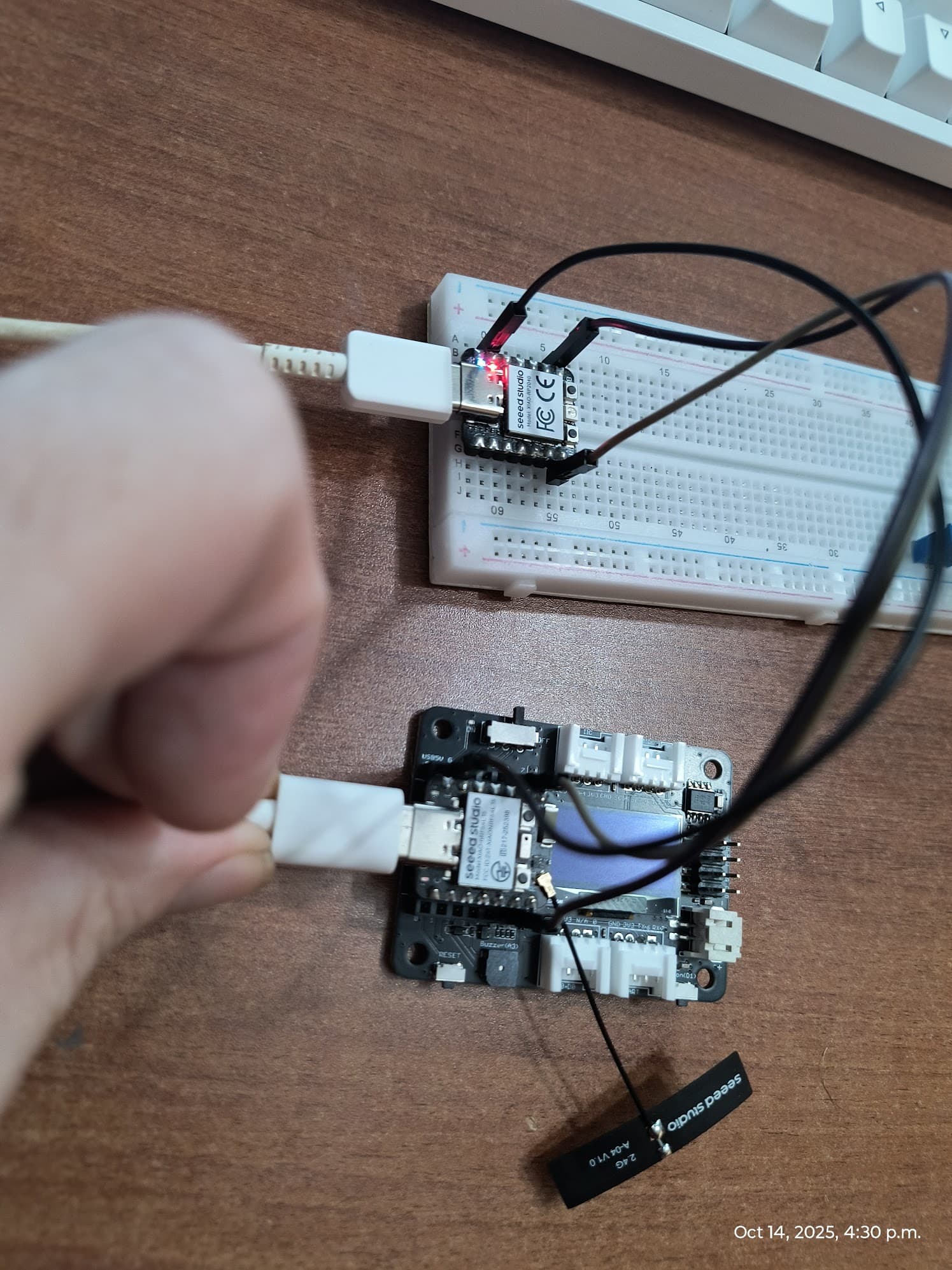
I’ve ported Arduino core for the Xiao NRF54L15 . Most of the stuff are working. Still a lot of testing to do. I still have to do a bit of work. The core is using Zephyr for now under the hood as pure Arduino implementation is still W.I.P. (specially for radio stuff and some peripherals).
I will have to look into it if i can send it with a part of Zephyr or just add build instructions.