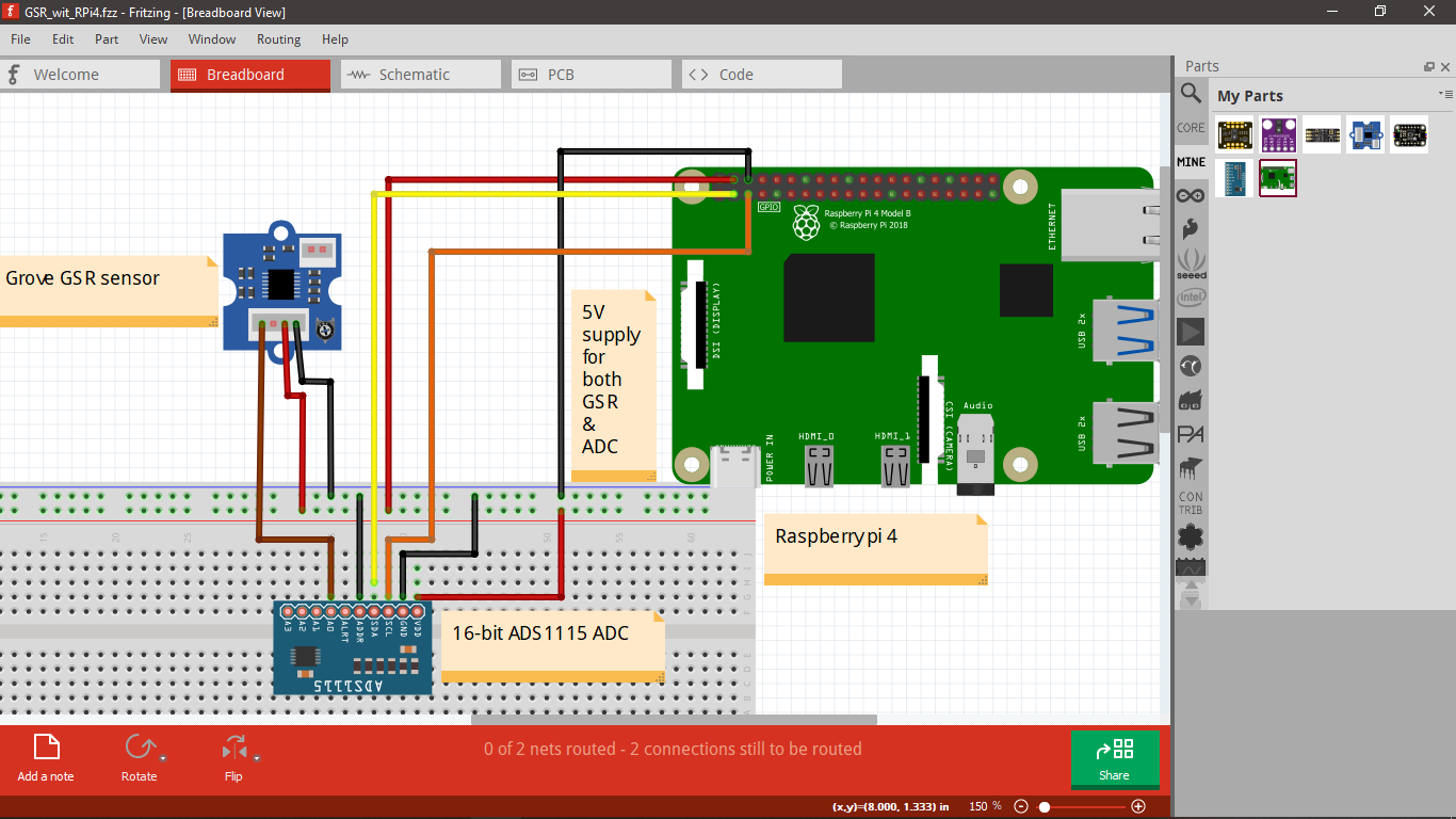
This is my code to get GSR readings from Grove GSR sensor through 16-bit ADS1115 in RPi 4.I attached the output below, is that I’m getting right form of readings or I need to do any calculations or conversions?
First I implemented it in my ESP8266 using below Arduino code and here they using the threshold value and I thought I were missing that in my RPi implementation. Is that true?
Arduino code:
const int BUZZER=3;
const int GSR=A2;
int threshold=0;
int sensorValue;
void setup(){
long sum=0;
Serial.begin(9600);
pinMode(BUZZER,OUTPUT);
digitalWrite(BUZZER,LOW);
delay(1000);
for(int i=0;i<500;i++)
{
sensorValue=analogRead(GSR);
sum += sensorValue;
delay(5);
}
threshold = sum/500;
Serial.print("threshold =");
Serial.println(threshold);
}
void loop(){
int temp;
sensorValue=analogRead(GSR);
Serial.print("sensorValue=");
Serial.println(sensorValue);
temp = threshold - sensorValue;
if(abs(temp)>50)
{
sensorValue=analogRead(GSR);
temp = threshold - sensorValue;
if(abs(temp)>50){
digitalWrite(BUZZER,HIGH);
Serial.println("YES!");
delay(3000);
digitalWrite(BUZZER,LOW);
delay(1000);}
}
}
RPi python code for GSR:
import time
import board
import busio
import adafruit_ads1x15.ads1115 as ADS
from adafruit_ads1x15.analog_in import AnalogIn

# Initialize the I2C bus
i2c = busio.I2C(board.SCL, board.SDA)  # Specify the I2C frequency if necessary

# Create an ADS1115 ADC object
ads = ADS.ADS1115(i2c, address=0x48)

# Create an analog input channel
channel = AnalogIn(ads, ADS.P0)  # Use the appropriate channel (P0 or P1)

while True:
    gsr_value = channel.value
    print("GSR Value:", gsr_value)
    time.sleep(1)
Output:
GSR Value: 881
GSR Value: 983
GSR Value: 938
GSR Value: 922
GSR Value: 1013
GSR Value: 841
GSR Value: 1050
GSR Value: 931
GSR Value: 847
GSR Value: 1068
GSR Value: 903