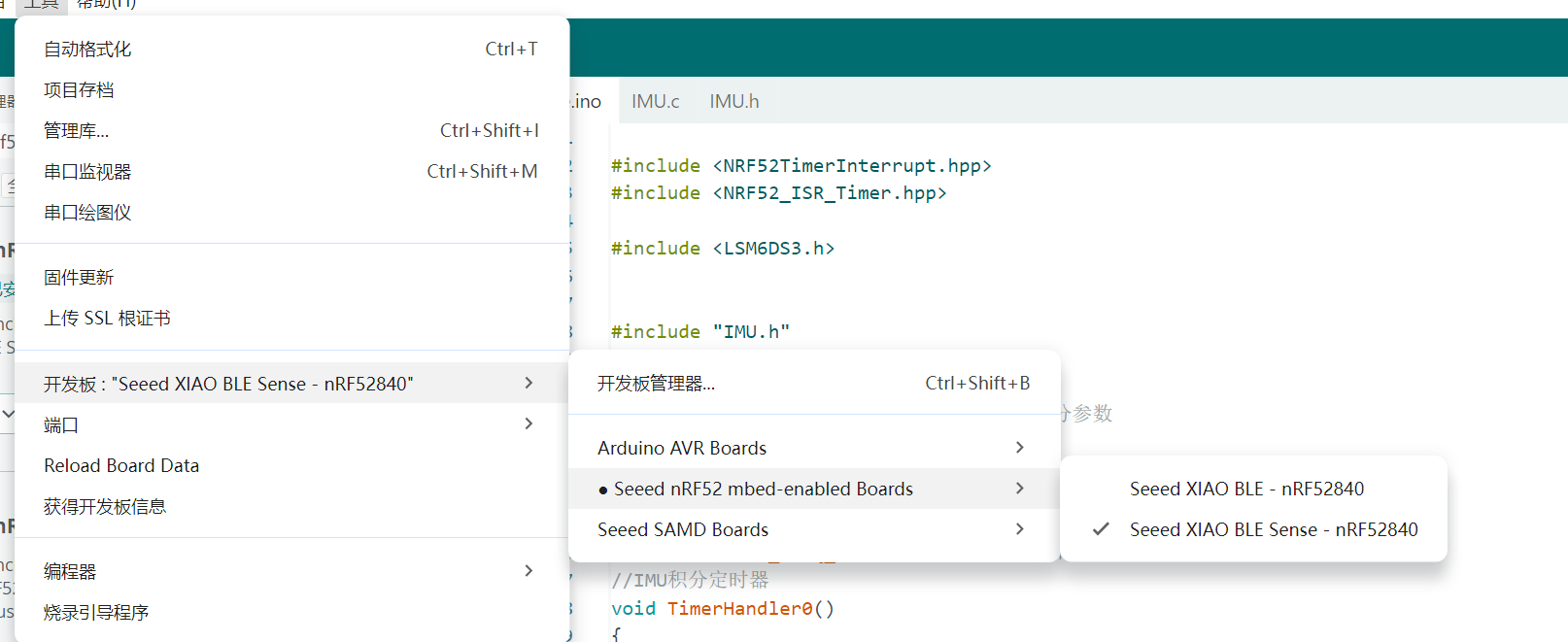
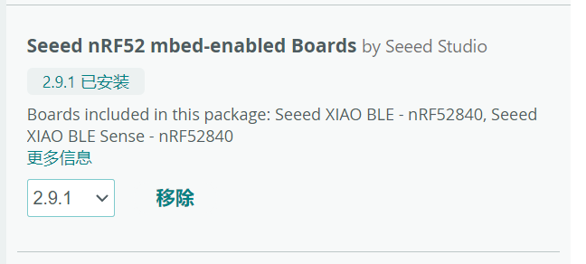
I haved used the board xiao mrf52840.But It brings bugs that weren’t there before:
In file included from D:\arduio doucument\hudie\IMU.c:1:0:
d:\arduio doucument\libraries\Seeed_Arduino_LSM6DS3/LSM6DS3.h:51:1: error: unknown type name 'class'
 class LSM6DS3Core {
 ^~~~~
d:\arduio doucument\libraries\Seeed_Arduino_LSM6DS3/LSM6DS3.h:51:19: error: expected '=', ',', ';', 'asm' or '__attribute__' before '{' token
 class LSM6DS3Core {
                   ^
d:\arduio doucument\libraries\Seeed_Arduino_LSM6DS3/LSM6DS3.h:92:3: error: expected specifier-qualifier-list before 'public'
   public:
   ^~~~~~
d:\arduio doucument\libraries\Seeed_Arduino_LSM6DS3/LSM6DS3.h:134:1: error: unknown type name 'class'
 class LSM6DS3 : public LSM6DS3Core {
 ^~~~~
d:\arduio doucument\libraries\Seeed_Arduino_LSM6DS3/LSM6DS3.h:134:15: error: expected '=', ',', ';', 'asm' or '__attribute__' before ':' token
 class LSM6DS3 : public LSM6DS3Core {
               ^
D:\arduio doucument\hudie\IMU.c:5:1: error: unknown type name 'LSM6DS3'
In file included from D:\arduio doucument\hudie\IMU.c:1:0:
d:\arduio doucument\libraries\Seeed_Arduino_LSM6DS3/LSM6DS3.h:32:18: error: expected declaration specifiers or '...' before numeric constant
 #define I2C_MODE 0
                  ^
D:\arduio doucument\hudie\IMU.c:5:15: note: in expansion of macro 'I2C_MODE'
D:\arduio doucument\hudie\IMU.c:5:25: error: expected declaration specifiers or '...' before numeric constant
D:\arduio doucument\hudie\IMU.c:8:0: warning: "M_PI" redefined
In file included from D:\arduio doucument\hudie\IMU.c:3:0:
c:\users\32494\appdata\local\arduino15\packages\seeeduino\tools\arm-none-eabi-gcc\7-2017q4\arm-none-eabi\include\math.h:617:0: note: this is the location of the previous definition
 #define M_PI  3.14159265358979323846

D:\arduio doucument\hudie\IMU.c: In function 'IMU_init':
D:\arduio doucument\hudie\IMU.c:23:4: error: 'myIMU' undeclared (first use in this function)
D:\arduio doucument\hudie\IMU.c:23:4: note: each undeclared identifier is reported only once for each function it appears in
D:\arduio doucument\hudie\IMU.c: In function 'bsp_IcmGetRawData':
D:\arduio doucument\hudie\IMU.c:116:24: error: 'myIMU' undeclared (first use in this function)
Using library Seeed Arduino LSM6DS3 at version 2.0.4 in folder: D:\arduio doucument\libraries\Seeed_Arduino_LSM6DS3
Using library NRF52_TimerInterrupt at version 1.4.2 in folder: D:\arduio doucument\libraries\NRF52_TimerInterrupt
Using library Adafruit TinyUSB Library at version 1.7.0 in folder: C:\Users\32494\AppData\Local\Arduino15\packages\Seeeduino\hardware\Seeed_nRF52_Boards\libraries\Adafruit_TinyUSB_Arduino
Using library Wire at version 1.0 in folder: C:\Users\32494\AppData\Local\Arduino15\packages\Seeeduino\hardware\Seeed_nRF52_Boards\libraries\Wire
Using library SPI at version 1.0 in folder: C:\Users\32494\AppData\Local\Arduino15\packages\Seeeduino\hardware\Seeed_nRF52_Boards\libraries\SPI
exit status 1

Compilation error: exit status 1
And this is my code of IMU.c
#include <LSM6DS3.h>

#include <math.h>

LSM6DS3 myIMU(I2C_MODE, 0x6A);    //I2C device address 0x6A

extern uint32_t nowtime;
#define MM_PI  (float)3.1415926535
float TTangles_gyro[6]; //彤彤滤波角度
volatile float exInt, eyInt, ezInt;  // 误差积分
volatile float q0, q1, q2, q3; // 全局四元数
static double Gyro_fill[3][300];
static double Gyro_total[3];
static double sqrGyro_total[3];
static int GyroinitFlag = 0;
static int GyroCount = 0;
volatile uint32_t lastUpdate, now; // 采样周期计数 单位 us
int imu660ra_acc_x,imu660ra_acc_y,imu660ra_acc_z;
int imu660ra_gyro_x,imu660ra_gyro_y,imu660ra_gyro_z;

void IMU_init(void)
{
   myIMU.settings.gyroEnabled = 1;  //Can be 0 or 1
  myIMU.settings.gyroRange = 1000;   //Max deg/s.  Can be: 125, 245, 500, 1000, 2000
  myIMU.settings.gyroSampleRate = 833;   //Hz.  Can be: 13, 26, 52, 104, 208, 416, 833, 1666
  myIMU.settings.gyroBandWidth = 200;  //Hz.  Can be: 50, 100, 200, 400;
  myIMU.settings.gyroFifoEnabled = 1;  //Set to include gyro in FIFO
  myIMU.settings.gyroFifoDecimation = 1;  //set 1 for on /1

  myIMU.settings.accelEnabled = 1;
  myIMU.settings.accelRange = 4;      //Max G force readable.  Can be: 2, 4, 8, 16
  myIMU.settings.accelSampleRate = 833;  //Hz.  Can be: 13, 26, 52, 104, 208, 416, 833, 1666, 3332, 6664, 13330
  myIMU.settings.accelBandWidth = 200;  //Hz.  Can be: 50, 100, 200, 400;
  myIMU.settings.accelFifoEnabled = 1;  //Set to include accelerometer in the FIFO
  myIMU.settings.accelFifoDecimation = 1;  //set 1 for on /1
  myIMU.settings.tempEnabled = 1;

  //Non-basic mode settings
  myIMU.settings.commMode = 1;


   myIMU.settings.fifoModeWord = 0;
  myIMU.begin();


  	q0 = 1.0f;
		q1 = 0.0f;
		q2 = 0.0f;
		q3 = 0.0f;
		exInt = 0.0;
		eyInt = 0.0;
		ezInt = 0.0;
		lastUpdate = nowtime;
		now = nowtime;
}
// 方差变形公式 S^2 = (X1^2 + X2^2 + X3^2 + ... +Xn^2)/n - X平均^2
// 函数名称: calVariance
// 功能描述: 计算方差
// 输入参数: data[] --- 参与计算方差的数据缓冲区
//           length --- 数据长度
// 输出参数:                                                                                      */
//           sqrResult[] --- 方差结果
//           avgResult[] --- 平均数

void calGyroVariance(float data[], int length, float sqrResult[], float avgResult[])
{
	int i;
	double tmplen;
	if (GyroinitFlag == 0)
	{
		for (i = 0; i< 3; i++)
		{
			Gyro_fill[i][GyroCount] = data[i];
			Gyro_total[i] += data[i];
			sqrGyro_total[i] += data[i] * data[i];
			sqrResult[i] = 100;
			avgResult[i] = 0;
		}
	}
	else
	{
		for (i = 0; i< 3; i++)
		{
			Gyro_total[i] -= Gyro_fill[i][GyroCount];
			sqrGyro_total[i] -= Gyro_fill[i][GyroCount] * Gyro_fill[i][GyroCount];
			Gyro_fill[i][GyroCount] = data[i];
			Gyro_total[i] += Gyro_fill[i][GyroCount];
			sqrGyro_total[i] += Gyro_fill[i][GyroCount] * Gyro_fill[i][GyroCount];
		}
	}
	GyroCount++;
	if (GyroCount >= length)
	{
		GyroCount = 0;
		GyroinitFlag = 1;
	}
	if (GyroinitFlag == 0)
	{
		return;
	}
	tmplen = length;
	for (i = 0; i< 3; i++)
	{
		avgResult[i] = (float)(Gyro_total[i] / tmplen);
		sqrResult[i] = (float)((sqrGyro_total[i] - Gyro_total[i] * Gyro_total[i] / tmplen) / tmplen);
	}
}

int bsp_IcmGetRawData(float accel_mg[3], float gyro_dps[3])
{


      imu660ra_acc_x = myIMU.readRawAccelX();
      imu660ra_acc_y = myIMU.readRawAccelY();
      imu660ra_acc_z = myIMU.readRawAccelZ();
      imu660ra_gyro_x = myIMU.readRawGyroX();
      imu660ra_gyro_y = myIMU.readRawGyroY();
      imu660ra_gyro_z = myIMU.readRawGyroZ();
	accel_mg[0] = (float)(imu660ra_acc_x* 4 /* mg */) / 32.768;
	accel_mg[1] = (float)(imu660ra_acc_y* 4 /* mg */) / 32.768;
	accel_mg[2] = (float)(imu660ra_acc_z* 4 /* mg */) / 32.768;
	gyro_dps[0] = (float)(imu660ra_gyro_x* 1000 /* dps */) / 32768.0;
	gyro_dps[1] = (float)(imu660ra_gyro_y* 1000 /* dps */) / 32768.0;
	gyro_dps[2] = (float)(imu660ra_gyro_z* 1000 /* dps */) / 32768.0;

	return 0;
}
float my_gyro_offset[3] = {0};
int CalCount = 0;
/**************************实现函数********************************************
*函数原型:	   void IMU_getValues(float * values)
*功  能:	 读取加速度 陀螺仪 磁力计 的当前值
输入参数: 将结果存放的数组首地址
输出参数:没有
*******************************************************************************/
void IMU_getValues(float * values) {
	float accgyroval[6];
//	icm42688RealData_t accval;
//	icm42688RealData_t gyroval;

	float sqrResult_gyro[3];
	float avgResult_gyro[3];
	//读取加速度和陀螺仪的当前ADC
	bsp_IcmGetRawData(accgyroval, &accgyroval[3]);
    TTangles_gyro[0] =  accgyroval[0];
    TTangles_gyro[1] =  accgyroval[1];
    TTangles_gyro[2] =  accgyroval[2];
	TTangles_gyro[3] =  accgyroval[3];
	TTangles_gyro[4] =  accgyroval[4];
	TTangles_gyro[5] =  accgyroval[5];


	calGyroVariance(&TTangles_gyro[3], 100, sqrResult_gyro, avgResult_gyro);
	if (sqrResult_gyro[0] < 0.02f && sqrResult_gyro[1] < 0.02f && sqrResult_gyro[2] < 0.02f && CalCount >= 99)
	{
		my_gyro_offset[0] = avgResult_gyro[0];
		my_gyro_offset[1] = avgResult_gyro[1];
		my_gyro_offset[2] = avgResult_gyro[2];
		exInt = 0;
		eyInt = 0;
		ezInt = 0;
		CalCount = 0;
	}
	else if (CalCount < 100)
	{
		CalCount++;
	}
    values[0] =  accgyroval[0];
    values[1] =  accgyroval[1];
    values[2] =  accgyroval[2];
	values[3] =  accgyroval[3] - my_gyro_offset[0];
	values[4] =  accgyroval[4] - my_gyro_offset[1];
	values[5] =  accgyroval[5] - my_gyro_offset[2];


		//这里已经将量程改成了 1000度每秒  32.8 对应 1度每秒
}
// Fast inverse square-root
/**************************实现函数********************************************
*函数原型:	   float invSqrt(float x)
*功  能:	   快速计算 1/Sqrt(x)
输入参数: 要计算的值
输出参数: 结果
*******************************************************************************/
float invSqrt1(float x) {
	float halfx = 0.5f * x;
	float y = x;
	long i = *(long*)&y;
	i = 0x5f3759df - (i>>1);
	y = *(float*)&i;
	y = y * (1.5f - (halfx * y * y));
	return y;
}

/**************************实现函数********************************************
*函数原型:	   void IMU_AHRSupdate
*功  能:	 更新AHRS 更新四元数
输入参数: 当前的测量值。
输出参数:没有
*******************************************************************************/
#define Kp 0.5f   // proportional gain governs rate of convergence to accelerometer/magnetometer
#define Ki 0.001f   // integral gain governs rate of convergence of gyroscope biases

void IMU_AHRSupdate(float gx, float gy, float gz, float ax, float ay, float az) {
  float norm;
  //float hx, hy, hz, bx, bz;
  float vx, vy, vz;//, wx, wy, wz;
  float ex, ey, ez,halfT;
  float tempq0,tempq1,tempq2,tempq3;

  // 先把这些用得到的值算好
  float q0q0 = q0*q0;
  float q0q1 = q0*q1;
  float q0q2 = q0*q2;
  float q0q3 = q0*q3;
  float q1q1 = q1*q1;
  float q1q2 = q1*q2;
  float q1q3 = q1*q3;
  float q2q2 = q2*q2;
  float q2q3 = q2*q3;
  float q3q3 = q3*q3;
////====================================================================================================================================
//	//20160323v0.4.6
//	//此处增加了一些机动检测使用的变量
//	//设置延迟启动机动检测的判据
//	static int s_InitTickCount=0;
//	float an[3]={0,0,0};
//	float Cb2n[3*3]={0};
//

////====================================================================================================================================
//

  now = nowtime;  //读取时间
  if(now<lastUpdate){ //定时器溢出过了。
  halfT =  ((float)(now + (0xffff- lastUpdate)) / 20000.0f);
  }
  else	{
  halfT =  ((float)(now - lastUpdate) / 20000.0f);
  }
  lastUpdate = now;	//更新时间

  norm = invSqrt1(ax*ax + ay*ay + az*az);
  ax = ax * norm;
  ay = ay * norm;
  az = az * norm;
  //把加计的三维向量转成单位向量。

//  norm = invSqrt1(mx*mx + my*my + mz*mz);
//  mx = mx * norm;
//  my = my * norm;
//  mz = mz * norm;

  /*
  这是把四元数换算成《方向余弦矩阵》中的第三列的三个元素。
根据余弦矩阵和欧拉角的定义,地理坐标系的重力向量,转到机体坐标系,正好是这三个元素。
所以这里的vx\y\z,其实就是当前的欧拉角(即四元数)的机体坐标参照系上,换算出来的重力单位向量。
  */
  // compute reference direction of flux
//  hx = 2*mx*(0.5f - q2q2 - q3q3) + 2*my*(q1q2 - q0q3) + 2*mz*(q1q3 + q0q2);
//  hy = 2*mx*(q1q2 + q0q3) + 2*my*(0.5f - q1q1 - q3q3) + 2*mz*(q2q3 - q0q1);
//  hz = 2*mx*(q1q3 - q0q2) + 2*my*(q2q3 + q0q1) + 2*mz*(0.5f - q1q1 - q2q2);
//  bx = sqrt((hx*hx) + (hy*hy));
//  bz = hz;

  // estimated direction of gravity and flux (v and w)
  vx = 2*(q1q3 - q0q2);
  vy = 2*(q0q1 + q2q3);
  vz = q0q0 - q1q1 - q2q2 + q3q3;

//  /* 加速度:由南向北方向的加速度在加速度计X分量 */
//	north.x = 1 - 2*(q3*q3 + q2*q2);
//	/* 加速度:由南向北方向的加速度在加速度计Y分量 */
//	north.y = 2* (-q0*q3 + q1*q2);
//	/* 加速度:由南向北方向的加速度在加速度计Z分量 */
//	north.z = 2* (+q0*q2  - q1*q3);
//	/* 加速度:由东向西方向的加速度在加速度计X分量 */
//	west.x = 2* (+q0*q3 + q1*q2);
//	/* 加速度:由东向西方向的加速度在加速度计Y分量 */
//	west.y = 1 - 2*(q3*q3 + q1*q1);
//	/* 加速度:由东向西方向的加速度在加速度计Z分量 */
//	west.z = 2* (-q0*q1 + q2*q3);
//  wx = 2*bx*(0.5 - q2q2 - q3q3) + 2*bz*(q1q3 - q0q2);
//  wy = 2*bx*(q1q2 - q0q3) + 2*bz*(q0q1 + q2q3);
//  wz = 2*bx*(q0q2 + q1q3) + 2*bz*(0.5 - q1q1 - q2q2);

  // error is sum of cross product between reference direction of fields and direction measured by sensors
  ex = (ay*vz - az*vy);// + (my*wz - mz*wy);
  ey = (az*vx - ax*vz);// + (mz*wx - mx*wz);
  ez = (ax*vy - ay*vx);// + (mx*wy - my*wx);
  /*
  axyz是机体坐标参照系上,加速度计测出来的重力向量,也就是实际测出来的重力向量。
axyz是测量得到的重力向量,vxyz是陀螺积分后的姿态来推算出的重力向量,它们都是机体坐标参照系上的重力向量。
那它们之间的误差向量,就是陀螺积分后的姿态和加计测出来的姿态之间的误差。
向量间的误差,可以用向量叉积(也叫向量外积、叉乘)来表示,exyz就是两个重力向量的叉积。
这个叉积向量仍旧是位于机体坐标系上的,而陀螺积分误差也是在机体坐标系,而且叉积的大小与陀螺积分误差成正比,正好拿来纠正陀螺。(你可以自己拿东西想象一下)由于陀螺是对机体直接积分,所以对陀螺的纠正量会直接体现在对机体坐标系的纠正。
  */
if(ex != 0.0f && ey != 0.0f && ez != 0.0f){
  exInt = exInt + ex * Ki * halfT;
  eyInt = eyInt + ey * Ki * halfT;
  ezInt = ezInt + ez * Ki * halfT;

  // 用叉积误差来做PI修正陀螺零偏
  gx = gx + Kp*ex + exInt;
  gy = gy + Kp*ey + eyInt;
  gz = gz + Kp*ez + ezInt;

  }

  // 四元数微分方程
  tempq0 = q0 + (-q1*gx - q2*gy - q3*gz)*halfT;
  tempq1 = q1 + (q0*gx + q2*gz - q3*gy)*halfT;
  tempq2 = q2 + (q0*gy - q1*gz + q3*gx)*halfT;
  tempq3 = q3 + (q0*gz + q1*gy - q2*gx)*halfT;

  // 四元数规范化
  norm = invSqrt1(tempq0*tempq0 + tempq1*tempq1 + tempq2*tempq2 + tempq3*tempq3);
  q0 = tempq0 * norm;
  q1 = tempq1 * norm;
  q2 = tempq2 * norm;
  q3 = tempq3 * norm;
}

/**************************实现函数********************************************
*函数原型:	   void IMU_getQ(float * q)
*功  能:	 更新四元数 返回当前的四元数组值
输入参数: 将要存放四元数的数组首地址
输出参数:没有
*******************************************************************************/
float mygetqval[6];	//用于存放传感器转换结果的数组
void IMU_getQ(float * q) {

  IMU_getValues(mygetqval);
  //将陀螺仪的测量值转成弧度每秒
  //加速度和磁力计保持 ADC值 不需要转换
 IMU_AHRSupdate(mygetqval[3] * MM_PI/180, mygetqval[4] * MM_PI/180, mygetqval[5] * MM_PI/180,
   mygetqval[0], mygetqval[1], mygetqval[2]);

  q[0] = q0; //返回当前值
  q[1] = q1;
  q[2] = q2;
  q[3] = q3;
}


/**************************实现函数********************************************
*函数原型:	   void IMU_getYawPitchRoll(float * angles)
*功  能:	 更新四元数 返回当前解算后的姿态数据
输入参数: 将要存放姿态角的数组首地址
输出参数:没有
*******************************************************************************/
void IMU_getYawPitchRoll(float * angles) {
  float q[4]; // 四元数
  volatile float gx=0.0, gy=0.0, gz=0.0; //估计重力方向
  IMU_getQ(q); //更新全局四元数

  angles[0] = -atan2(2 * q[1] * q[2] + 2 * q[0] * q[3], -2 * q[2]*q[2] - 2 * q[3] * q[3] + 1)* 180/MM_PI; // yaw
  angles[1] = -asin(-2 * q[1] * q[3] + 2 * q[0] * q[2])* 180/MM_PI; // pitch
  angles[2] = atan2(2 * q[2] * q[3] + 2 * q[0] * q[1], -2 * q[1] * q[1] - 2 * q[2] * q[2] + 1)* 180/MM_PI; // roll
 // if(angles[0]<0)angles[0]+=360.0f;  //将 -+180度  转成0-360度
}

/*******************************************************************************************************************/
````预先格式化的文本`
And this is my code of IMU.h:
#ifndef IMU_NEW_H

#define IMU_NEW_H

extern float q0, q1, q2, q3; // 全局四元数

extern float exInt, eyInt, ezInt; // 误差积分

extern uint32_t lastUpdate, now; // 采样周期计数 单位 us

void IMU_getYawPitchRoll(float * angles);

void IMU_init(void);

#endif
Can you tell me why?