Is the original STLink properly connected to the LoRa-E5-mini?
My understanding is that the target device, the LoRa-E5-mini, needs to be powered via USB. Additionally, the STLink must be informed that the target voltage is 3.3V. I believe four wires need to be connected; please tell me where each one connects.
stlink lora e5 mini
swclk –> clk
swdio –> dio
gnd –> gnd
3.3v –> 3.3v
and i am also having a doubt if you used arduino ide in lora e5 mini will the at frimware will be gone in mini or not because out of 3 board i think i lost 1 board because of this method
The target device, the LoRa-E5-mini, needs to be powered via USB.
Is the STLink’s 3.3V pin an input pin? Or is it an output pin that supplies 3.3V to the target?
3.3 v is a output pin but i also tried via usb also but no respond from either method. and i tried in under reset method also what actually i did is i just followed the tutorial from seeed studion for wio e5 min after the customisation of the frimware they said go to cube programmer and change the rdp level from 1 to level 0 i changed accordingly after changes the board is not able to connect
tutorial link : Wio-E5 mini | Seeed Studio Wiki
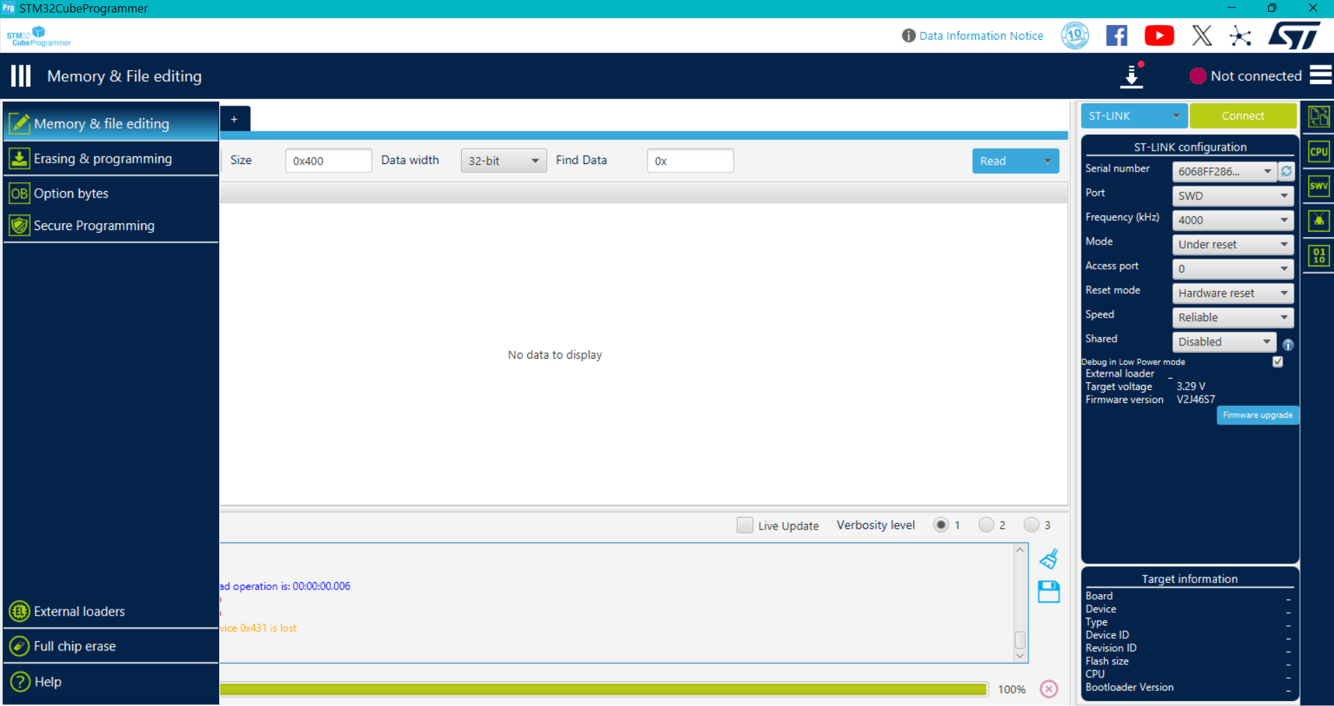
What are the device settings?
My STM32CubeProgrammer does not show the “Registers” tab like in your screenshot.
I only have the standard memory/file interface, and the device is not detected, so the registers view never appears.
Because the STM32WLE5 is not connecting over SWD, CubeProgrammer cannot load the device description and therefore does not display any register list.
actually my board is not connected if it is connected only i can see option bytes right and other stuff in my research i found that the sda pin has been bricked to unbrick that we need boot0 but e5 mini has not routed boot0 pin thats why the sda pin is not responding or can you say me if i use a new lora e5 mini with arduino ide and uploaded the code will the frimware in lora e5 mini will be gone why i am asking this because i cannot risk another board
I erased the AT firmware on three LoRa-E5-mini devices and wrote a sketch using STLink, but no particular issues arose.
1 Like
can you say how you erased the frimware i just changed the rdp level from 1 to 0 whcih cause the mass erase have you any other method
Have you ever connected to stlink before?
Is there a problem with the connection wires?
Can you post a photo showing the connection status?
Changing the RDP means you were able to connect to stlink at least once, right?
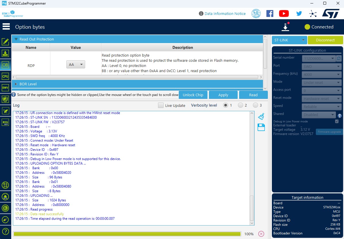
Yes, I was able to connect to the ST-Link once.
I successfully accessed the Option Bytes and changed the RDP level from 0xBB to 0xAA.
After that single successful connection, the board never connected again.
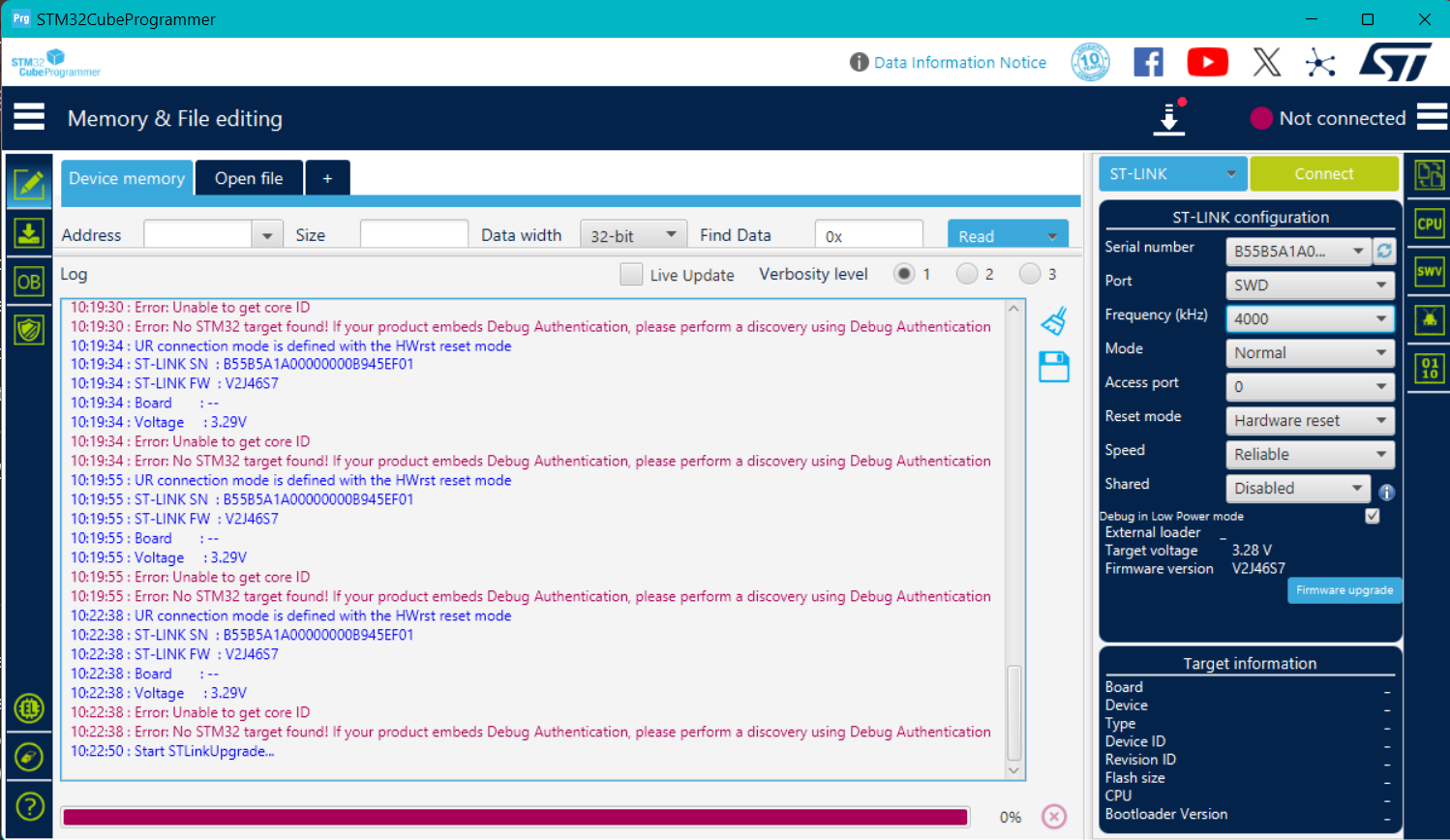
Now CubeProgrammer always shows:
“No STM32 target found” / “Error: Unable to get core ID”.
The wiring is correct (SWDIO → DIO, SWCLK → CLK, GND → GND, USB for power).
I have also tested the same ST-Link with other STM32 boards and it works normally.
So the problem seems specific to this Wio-E5 Mini module, not the programmer or wiring.
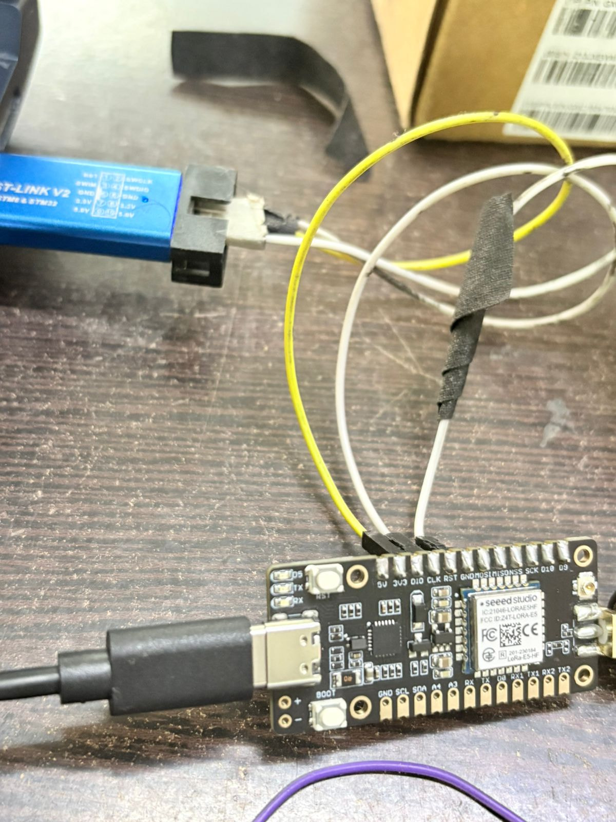
It’s hard to tell from this photo whether the wiring and connectors are reliable,
but if you have another board, why not try connecting it to see if it works?
Just be sure to thoroughly check the wiring’s reliability beforehand,
and avoid supplying power from both the STLink and USB simultaneously.
can you give me the procedure to do a p2p in lora e5 mini like wire connection and how to upload via arduino ide in simple words my goal is that both master and salve board should be auto configured it should not be changed after reset thats all but i cant use any external mcu
can you say how you erased the frimware in lora e5 mini
Please refer to this link.
After compiling in ArduinoIDE, upload to LoRa-E5-mini using STLink. You cannot upload via USB.
I believe AT firmware was erased using STLink. I don’t think I referred to anything other than the Wiki.
i aslo follwed the same method in wikki i am having a doubt can you explain how you erased the frimware using stlink in cube prgrmmer in simple words i changed the rdp level from 1 to level0 it caused the erase how did you did it then and i attached some image when i took after rdp changed from level 1 to level 0
this board is waste or it cannot been used again
thank you for everything so far it was so helpful
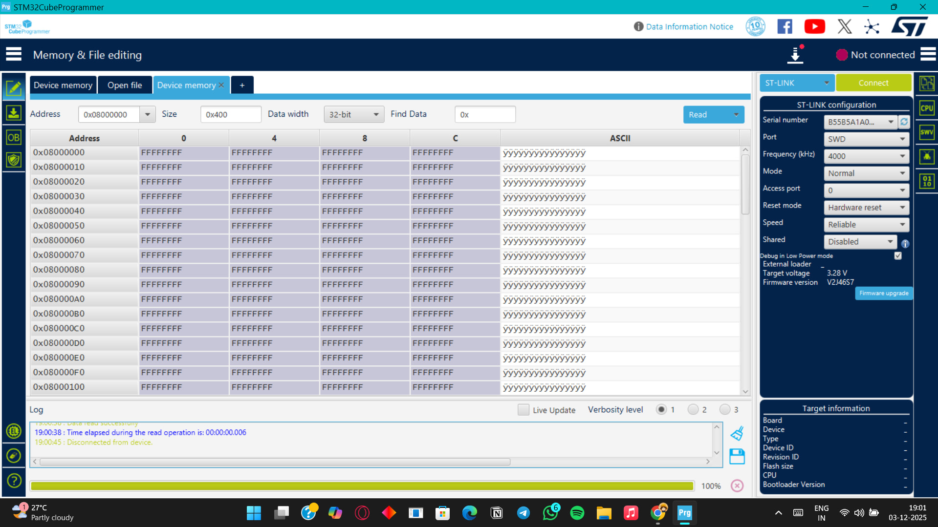

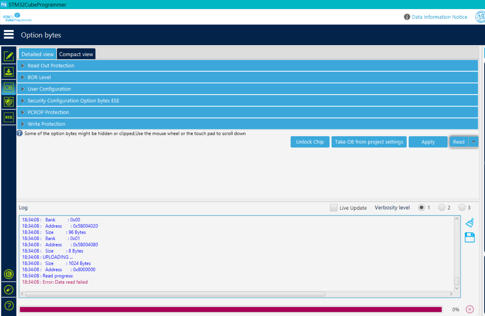

Looking at the screenshot, it appears stlink is running but unable to read data.
Is RDP set to AA or BB?
When powering the LoRa-E5 from USB, is the board’s 3V3 pin at 3.3V?
Can you try it on another LoRa-E5 board?
actually the stlink is connecting with other board it is fine but the stlink is undable to connect when i changed the rdp level from BB to AA after the changing and i clicked apply then after that the board disconnected that is the first and last time i connected the board after that i couldnt connect it
no i didnt powered via 3.3v while powering via usb
@msfujino can you say how you erased the frimware using stlink because i need to not make same mistake again
Have you tried this method?
It might require some trial and error, and the timing of the reset could be key, but it might work.
- Set the Programmer’s Mode to Under_reset,
- Set the Reset_Mode to Hardware_reset,
- While holding down the LoRa-E5-mini’s reset button,
- Click Connect on the Programmer,
- Release the LoRa-E5-mini’s reset button.
The reason I wanted to know the voltage on the 3V3 pin was to verify there were no issues with the LoRa-E5’s power supply system.
I have never actively erased the firmware using stlink; I have only overwritten it with new firmware.
Currently, is the RDP an AA or a BB? Please check the actual device.