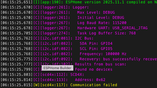
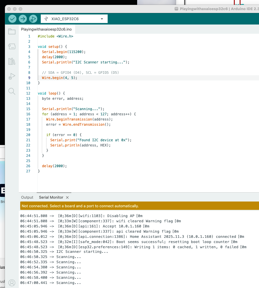
Hi all — I’m trying to connect the Seeed Studio XIAO ESP32-C6 to the Adafruit SCD41 (SCD4x) sensor, and the board flashes fine, but I²C scan shows no devices.
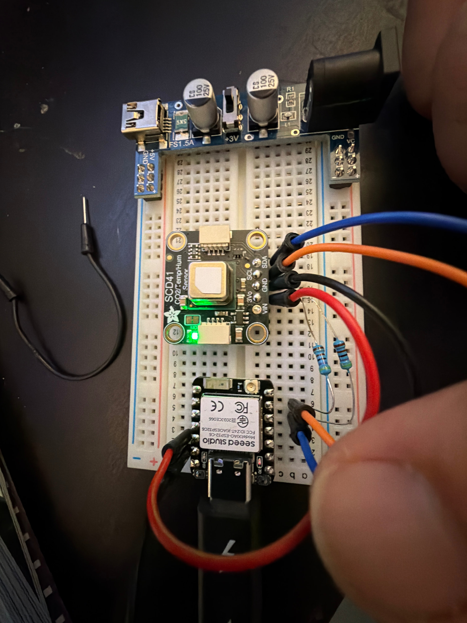
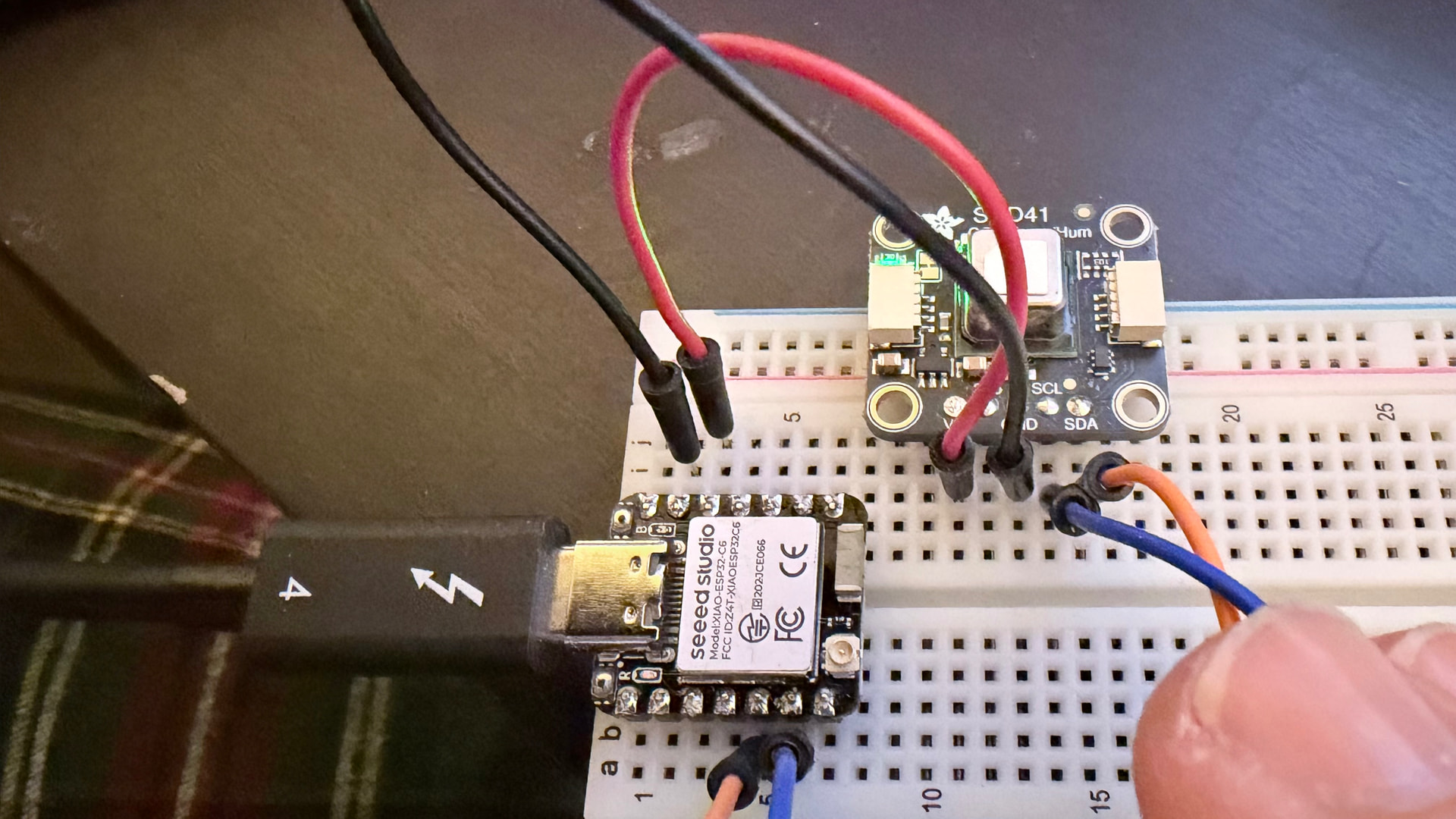
Can someone confirm the correct wiring?
Here’s what I think the correct connections are:
SCD41 VIN → 3V3 on the XIAO
SCD41 GND → GND
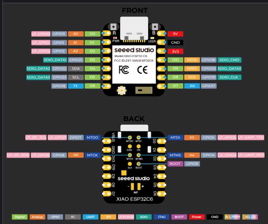
SCD41 SDA → D4 (GPIO4)
SCD41 SCL → D5 (GPIO5)
In yaml code:
i2c:
sda: GPIO4
scl: GPIO5
scan: true
I tested the same scd41 with a raspberry pi pico 2 w, and it works fine - so the sensor is good.
I just can’t get teh xiaoesp32c6 to detect the adafruit scd41
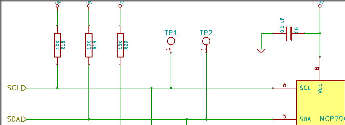
So , OK… You will need to start here and read through this… The Xiao is the same requires Pull-UP res. if your device doesn’t already have them.
More or less . I2C requires two pull-up resistors, one each for the SDA (data) and SCL (clock) lines, to pull the signals to a high state when the bus is not being actively driven low. These resistors are typically in the
2kΩ2 k ohm
to 10kΩ10 k cap ohm
range, with
4.7kΩ4.7 kohm
4.7𝑘Ω
and
10kΩ10 kohm
10𝑘Ω
being common values, and should be connected to the same voltage supply as the devices’ logic level. Many I2C breakout boards have these resistors built-in.
Role of pull-up resistors in I2C
Default state: The I2C bus uses open-drain or open-collector configurations, meaning devices can pull the line low but not high. Pull-up resistors provide a default high state for the bus lines.
Bus operation: When a device is not transmitting, the pull-up resistor pulls the signal line high. When a device wants to send a low bit, it connects the line to ground, overriding the pull-up resistor.
Multiple devices: Using pull-up resistors ensures that only one device can actively pull the line low at a time. If every device had an integrated pull-up resistor, the driving device would have to handle the current from all of them.
I made sure the resistor were what you specified. What I found out was other I2C sensors did not play nice with this chip either.
I bought 3 of these, one was broke out of the box and the other 2 chips act similarly. So at this stage all fingers point to this chip. I wish it worked but I need to move to other esp32 that I know work.
Thanks again, I learned a lot.
Honestly, I had high hopes for using the heck out of this.
On the ESP32C6, D4 = GPIO22 and D5 = GPIO23.
If you post a photo of the SCD41 and XIAO connection and the I2C scan sketch you tried, we might be able to figure something out.
VIN - This is the power pin. To power the board, give it the same power as the logic level of your microcontroller - e.g. for a 3V microcontroller like a Feather M4, use 3V, or for a 5V microcontroller like Arduino, use 5V.
3Vo - This is the output from the onboard 3.3V regulator. If you have a need for a clean 3.3V output, you can use this! It can provide at least 100mA output.
GND - This is common ground for power and logic.
The 3Vo pin is a 3.3V output terminal. Connect 3.3V to the VIN pin.
Any other microprocessor works fine. I am not spending any more time on this. I need to make progress and not spin my wheels. Let me know if someone else figures this out.