How can I charge the battery faster than 150 mA on the Xiao RA4M1?

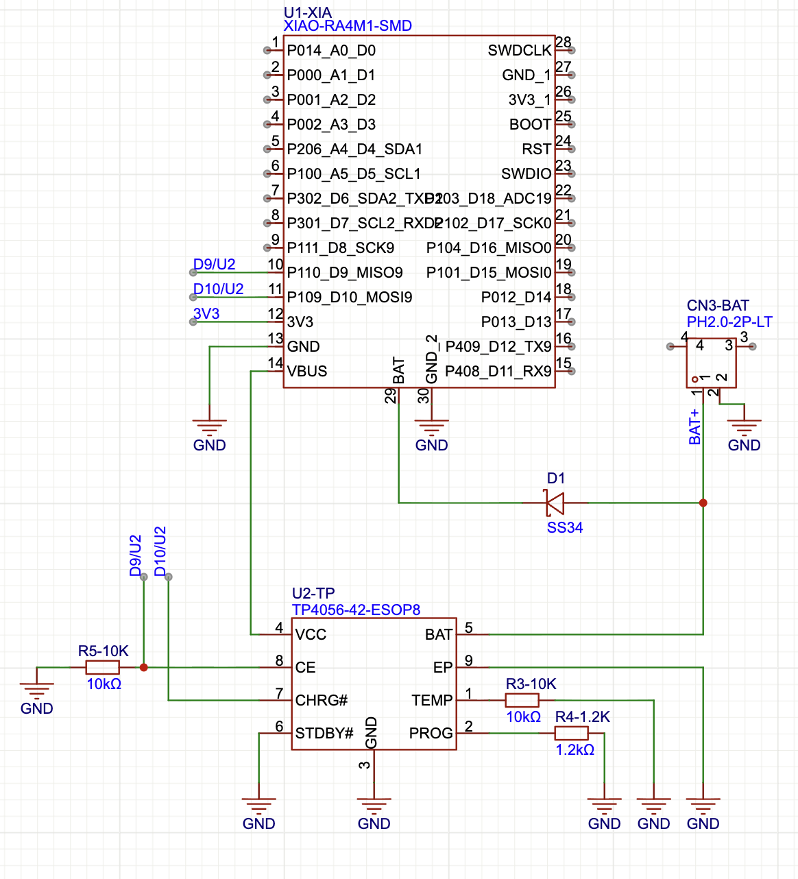
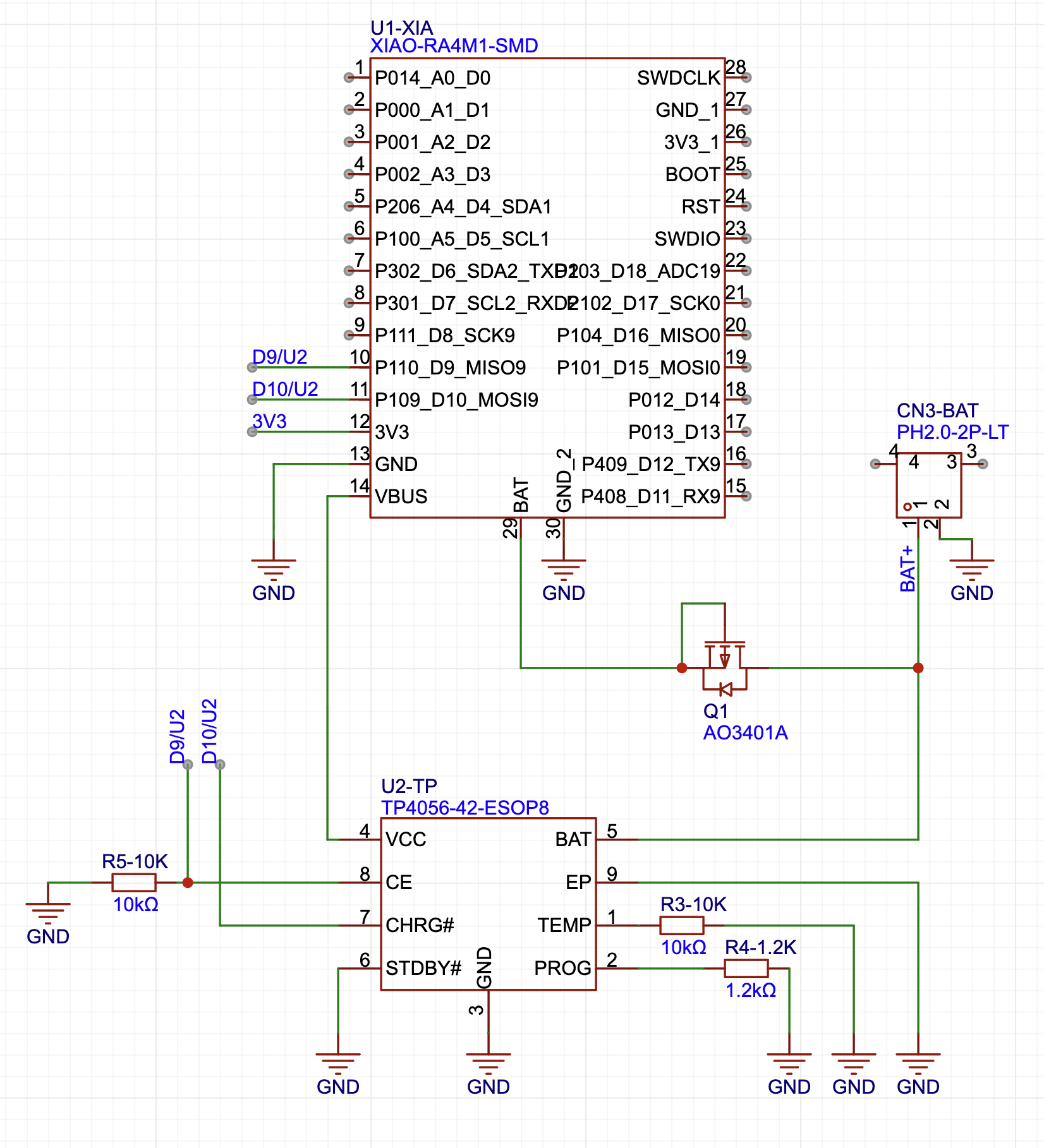
I have a Xiao RA4M1 connected to a 5000 mAh battery via the BAT+ and BAT- pins. It works great and charges the battery when I connect the USBC. The problem is that it is unbearably slow, 150 mA. I need to charge at least at 1A. What is the simplest way to make this happen? The only requisite is that it must be charged using the USBC port of the Xiao board.

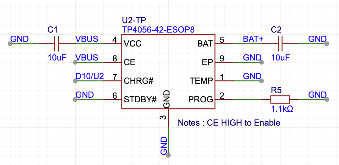
Maybe a TP4056 could fix my issues, but I don’t know how to make it all work together. Can I simply connect the battery to both the BAT pins of the Xiao so that it powers it, and also to the BAT pin of the TP4056 so basically I have two chargers at the same time (150 mA + 1A) or will this make things explode?

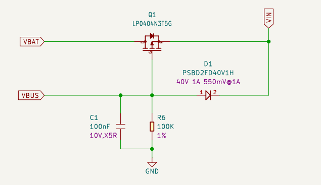
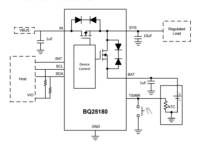
What’s the recommended way to power the Xiao with a big battery that also needs to be charged via the USBC of the Xiao?

Connecting two chargers to the battery is dangerous.

https://www.aliexpress.us/item/3256808606364019.html

Not to disagree with my friend…MF and with saying that dealing with battery is dangerious and dont use this with production, I will say this

It appears the “Charging” circuit of the XIAO is not that sophisticated… its basicly a 4.7v voltage regulator/gate 4.7v←>4.7v

so i would say try the unit you discribed… according to the link above, schematic, i would say

2 options power thru XIAO USB or Power thru TP USB

try hook the XIAO bottom to the Load Side, provide 18650 and power the device via TP unit

or connect 5V pin and GND of XIAO to USB Power IN on the TP

I was going to draw a schematic… but i couldnt scrape the image from the internet

I have not done any testing, so please report back your findings, but my basic opinion is the under battery pins can equally be used to power the XIAO, and this is the better way to do so, rather than using the 5V pin, or the (needs regulated) 3v3 which many people have had problems with.

also be awair without a diode, you could backfeed your USB, so do not connect to a computer or sensitive device… if using data, disconect the power at pin 5v for maximum safety for upstream devices. you dont want a high current backfeed.

I assume you are powering with a fast usb charger, do not leave the experiment unattended watch for fire or heat.

The TP4056 I want to use is just the IC without any USB port, so there is no “LOAD” pins, it only charges the battery, check datasheet.

I created this schematic. The relevant part is the battery connector (CN3-BAT) on the right, which connects the battery (BAT+) to both the BAT pin of the Xiao and the BAT pin of the TP4056 1A linear charger. I also added a D1 Schottky diode (SS34) to prevent the integrated Xiao charger to charge the batter at the same time. But I don’t know if this is better or worse. Should this work? Is it safer with D1?

I can also control when the TP4056 charges via software by setting CE high, and know if it is currently charging by checking CHRG# (D9 and D10 pins of the Xiao), in case it is useful.

yes this looks interesting… the diode in that case is keeping the XIAO from backfeeding the battery directly… I might say test with a diode/switch or a transistor that can switch either way

I think worse case the xiao will screw up the voltage readings the IC is seeing and cause it to not charge correctly…. i mean the battery will discharge and the voltage output will drop… the xiao will suppliment the voltage drop and bring it back up to 4.5V and charge the battery, but this voltage rebound may trick the IC that charging is complete.. and you are doing this for high amp charging

so the point is the voltage feedback loop i am thinking

So you mean that when the Xiao tries to charge the battery, the TP4056 will see that 4.5v and think that the battery is already charged? I don’t understand this, shouldn’t the TP4056 always see the same voltage of the battery itself, so essentially everything that is connected to the Battery + pin will always be whatever voltage the battery has?

Hi there,

So I waiting for the " Diode " :grin: guy again… LOL
“We don’t need no stinking badges” :+1: but it’s NOT friday!

NO, would be the Answer. :crossed_fingers:

But hay, YOLO

HTH
GL :slight_smile: PJ :v:

Talking about diodes, I was told I could replace the SS34 diode with an AO3401A mosfet that should act as an “ideal diode” and thus prevent a voltage drop. But I don’t understand how to do that as a mosfet has 3 pins and I only have one wire.

I replaced Schottky diode SS34 with a AO3401A mosfet:

I’m not sure if my orientation of S, G, D is correct. Does this work the same as with the diode but without the voltage drop caused by the Schottky diode?

so you would have to test, i am not an expert, but yes this is what I am expecting

because the XIAO charger, based on user reaction appears to act as basicly a 4.7v

voltage regulator so when you power on the XAIO it will begin to try to “charge the battery” by generating the 4.7 on the bat line.

if the battery, lets say is at 3v3 it will start taking some of that voltage.. lets say half so the battery is showing 4v

so the charger is looking downstream it will either see the 4.7v from the XAIO

and think the battery is near overcharge or it will see the 4v but the battery will actually be a 3v3….

the diode would have prevented this, by being a one way vlave

as you can see i am not an expert, but you want it configured so the source side is the battery side and the drain side is the XIAO side I think you are going to want to tap to the gate on the battery side

I do this and it works fine. I’m using a BQ device though.

a BQ25180 maybe? And are you using a diode or “idea diode/mosfet”? It would be great if you could share the schematic to fully understand your method.

Basically it’s the same as the XIAO charging design. VBus turns off the VBat.

Edit> Since the BQ25180 has an integrated mosfet to isolate the battery from the SYS voltage, your approach should work fine, ie SYS voltage into the VBat on the XIAO base via a reverse biased diode (to prevent the XIAO’s charger from disrupting your charger - although I’d do some tests on whether that is an issue or not).

It looked promising, but I ended up deciding NOT to use the BAT pins of the Xiao. Thus I decided to connect the battery to an 3.3v LDO (an XC6227C331PR-G), and this to the Xiao’s 3V3 pin directly. Then the TP4056 will charge the battery from the VBUS as before.

These are the schematics. I still have not tried it, do you guys think it makes sense at least?

LDO:


Charger:

VBUS and 3V3 are the pins of the Xiao. BAT+ is the positive contact of the battery. The LDO should stop working when the Xiao is connected to the USBC, as this means the Xiao will already output 3V3.

2 Likes