The problem with the feedbacksensors is solved too. Now the device is 100% working.
I you want to know how i solved it, then look at the code. You can download the sourcecode at http://www.mechanicape.nl/hercules-4wd and http://www.mechanicape.nl/sites/default/files/hercules-131011a.zip
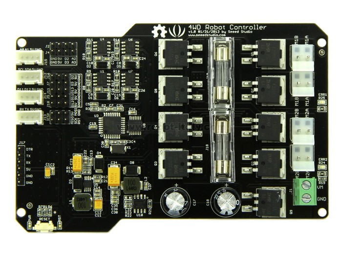
//MECHANICAPE.NL FIRMWARE FOR SEEEDSTUDIO HERCULES 4WD CONTROLLER
//Copyright By Rein Velt / http://mechanicape.nl
//May be used under the terms and conditions of Create Commons CC-BY-SA
//=====================================================================
// The device is controlled by serial commands. The command is send
// to the controllerboard. The controllerboard performs the
// requested action and sends a response message
// back to the requestor.
// The commands, descriptions and responses are:
//  CMD     DESCRIPTION                     RESPONSE
//  M0      Motor OFF                      -returns M0,speedL,speedR\n
//  M1      Motor Forward                  -returns M1,speedL,speedR\n
//  M2      Motor Reverse                  -returns M2,speedL,speedR\n
//  M3      Motor Turn Left (ccw)          -returns M3,speedL,speedR\n
//  M4      Motor Turn Right (cw)          -returns M4,speedL,speedR\n
//  MT      Motor Test (test motors)       -returns MT,speedL,speedR\n
//  S0..S9  Speed (0=stop,.., 9=fast)      -returns S*,speedL,speedR\n
//  B?      Query battery voltage          -returns B?,millivolts\n
//
//  the comma is used to separate commands when more are following
//  the newline is used to terminate one or more commands
//  eg:
//      M1\n
//      S5,M1,M1,S3,M2,M3,M0\n
//====================================================================

#include <avr/wdt.h>

// pin ctrl
#define PINRX           0           // receive serial data
#define PINTX           1           // send serial data
#define PININT0         2           // interrupt 0
#define PININT1         3           // interrupt 1
#define PINCS           6           // all motors cs
#define PINM1F          4           // motor 1 forward
#define PINM1R          5           // motor 1 reverse
#define PINM2F          7           // motor 2 forward
#define PINM2R          8           // motor 2 reverse
#define PINPWMA         9           // PWM channel A (motor A speed)
#define PINPWMB         10          // PWM channel B (motor B speed)
#define PINVS           A6          // voltage/battery sensor


//global vars
volatile int leftFeedback = 0;
volatile int rightFeedback = 0;
int motorSpeed=0;


void setup()
{
  //initialize pins (make them output)
  pinMode(PINCS, OUTPUT);
  pinMode(PINM1F, OUTPUT);
  pinMode(PINM1R, OUTPUT);
  pinMode(PINM2F, OUTPUT);
  pinMode(PINM2R, OUTPUT);
  pinMode(PINVS,  INPUT);

  //initialize motors
  motorStop();

  //initialize interrupts
  attachInterrupt(0, leftInterruptHandler, CHANGE);
  attachInterrupt(1, rightInterruptHandler, CHANGE);

  //initialize serial port
  Serial.begin(19200);
  Serial.println("//MECHANIC APE HERCULES 4WD ROBOTFIRMWARE V1.0");
  Serial.print("//Battery=");
  Serial.print(getBatteryVoltage());
  Serial.print("mV");
  Serial.println();
  Serial.println("OK");

  //initialize watch dog timer and set it to 2 seconds
  wdt_enable(WDTO_2S);
}


void loop()
{
  wdt_reset();  //reset watch dog timer
  processSerialData(); //read data from serial and send it to the motors
  resetFeedback();  //reset speed sensors
}


//**** INTERRUPT HANDLER ******************************************************************************


void leftInterruptHandler()
{
  leftFeedback++;
}


void rightInterruptHandler()
{
  rightFeedback++;
}


void resetFeedback()
{
  leftFeedback=0;
  rightFeedback=0;
}


//**** MOTOR CONTROLLER *******************************************************************************


void motorSetSpeed(int power)
{
  motorSpeed=power;
  analogWrite(PINPWMA,motorSpeed);
  analogWrite(PINPWMB,motorSpeed);
}


void motorStop()
{
  digitalWrite(PINCS,LOW);
  digitalWrite(PINM1R,LOW);
  digitalWrite(PINM1F,LOW);
  digitalWrite(PINM2F,LOW);
  digitalWrite(PINM2R,LOW);
}


void motorForward()
{
  digitalWrite(PINM1R,HIGH);
  digitalWrite(PINM1F,LOW);
  digitalWrite(PINM2F,HIGH);
  digitalWrite(PINM2R,LOW);
  digitalWrite(PINCS,HIGH);
}

void motorReverse()
{
  digitalWrite(PINM1R,LOW);
  digitalWrite(PINM1F,HIGH);
  digitalWrite(PINM2F,LOW);
  digitalWrite(PINM2R,HIGH);
  digitalWrite(PINCS,HIGH);
}


void motorTurnLeft()
{
  digitalWrite(PINM1R,LOW);
  digitalWrite(PINM1F,HIGH);
  digitalWrite(PINM2F,HIGH);
  digitalWrite(PINM2R,LOW);
  digitalWrite(PINCS,HIGH);
}


void motorTurnRight()
{
  digitalWrite(PINM1R,HIGH);
  digitalWrite(PINM1F,LOW);
  digitalWrite(PINM2F,LOW);
  digitalWrite(PINM2R,HIGH);
  digitalWrite(PINCS,HIGH);

}


//**** MESSAGE HANDLING ******************************************************************************


void processSerialData()
{
  if (Serial.available()>2)
  {
    int commandByte= Serial.read();
    int valueByte  = Serial.read();
    int endofline  = Serial.read();
    //a message has 3 bytes
    //this first byte is always M (Motor) or S (Speed)
    //the second byte is a number (0|1|2|3|4|..|9)
    //the third byte is a comma or a newline (,|\n)


    //handle the motor request
    if (commandByte==77 && (endofline==10 || endofline==44)) //M
    {
      //incoming data is correct and conform specs
      motorSetSpeed(motorSpeed);
      switch (valueByte)
      {
        //control the motors
      case 48+0:
        motorStop();
        break;       //M0\n
      case 48+1:
        motorForward();
        break;      //M1\n
      case 48+2:
        motorReverse();
        break;      //M2\n
      case 48+3:
        motorTurnLeft();
        break;     //M3\n
      case 48+4:
        motorTurnRight();
        break;     //M4\n
      case 84:
        motorTest(); //MT\n
        break;
      default:
        motorStop();
        break;    //fail safe
      } //end-switch

      //confirm the serial request by sending a response
      Serial.print(char(commandByte));
      Serial.print(char(valueByte));
      Serial.print(char(44));
      Serial.print(leftFeedback);
      Serial.print(char(44));
      Serial.print(rightFeedback);
      Serial.println();
    }

    //handle the motorspeed request
    if (commandByte==83 && (endofline==10 || endofline==44)) //S
    {
      //incoming data is correct and conform specs
      if (valueByte>47 && valueByte<59)
      {
        //set the motorspeed
        int motorNewSpeed=(valueByte-48)*26;
        motorSetSpeed(motorNewSpeed);

      }
      //confirm the serial request by sending a response
      Serial.print(char(commandByte));
      Serial.println(char(valueByte));
    }

    //handle the battery voltage request
    if (commandByte==66 && (endofline==10 || endofline==44)) //B
    {

      int millivolt=getBatteryVoltage();
      //confirm the serial request by sending a response
      Serial.print(char(commandByte));
      Serial.print(char(valueByte));
      Serial.print(char(44));
      Serial.print(millivolt);
      Serial.println();
    }

  }
  else
  {
    //no data
    motorStop();  //fail safe

  }
  delay(100); //this delay can be tweaked or omitted to adjust accuracy. keep it low!
}


//***** SENSOR HANDLING ******************************************************************************

int getBatteryVoltage()
{

  int value=analogRead(PINVS);
  int millivolt=round((float)(value)/0.037479); //guess
  return millivolt;
}
//***** SYSTEM TEST **********************************************************************************

void motorTest()
{
  for (int i=0;i<255;i++)
  {
    wdt_reset();
    motorSetSpeed(i);
    motorTurnRight();
    delay(50) ;
  }
  for (int i=255;i>-1;i--)
  {
    wdt_reset();
    motorSetSpeed(i);
    motorTurnRight();
    delay(50) ;
  }
  motorStop();
}
//*****************************************************************************************************
// * END FILE
// *****************************************************************************************************