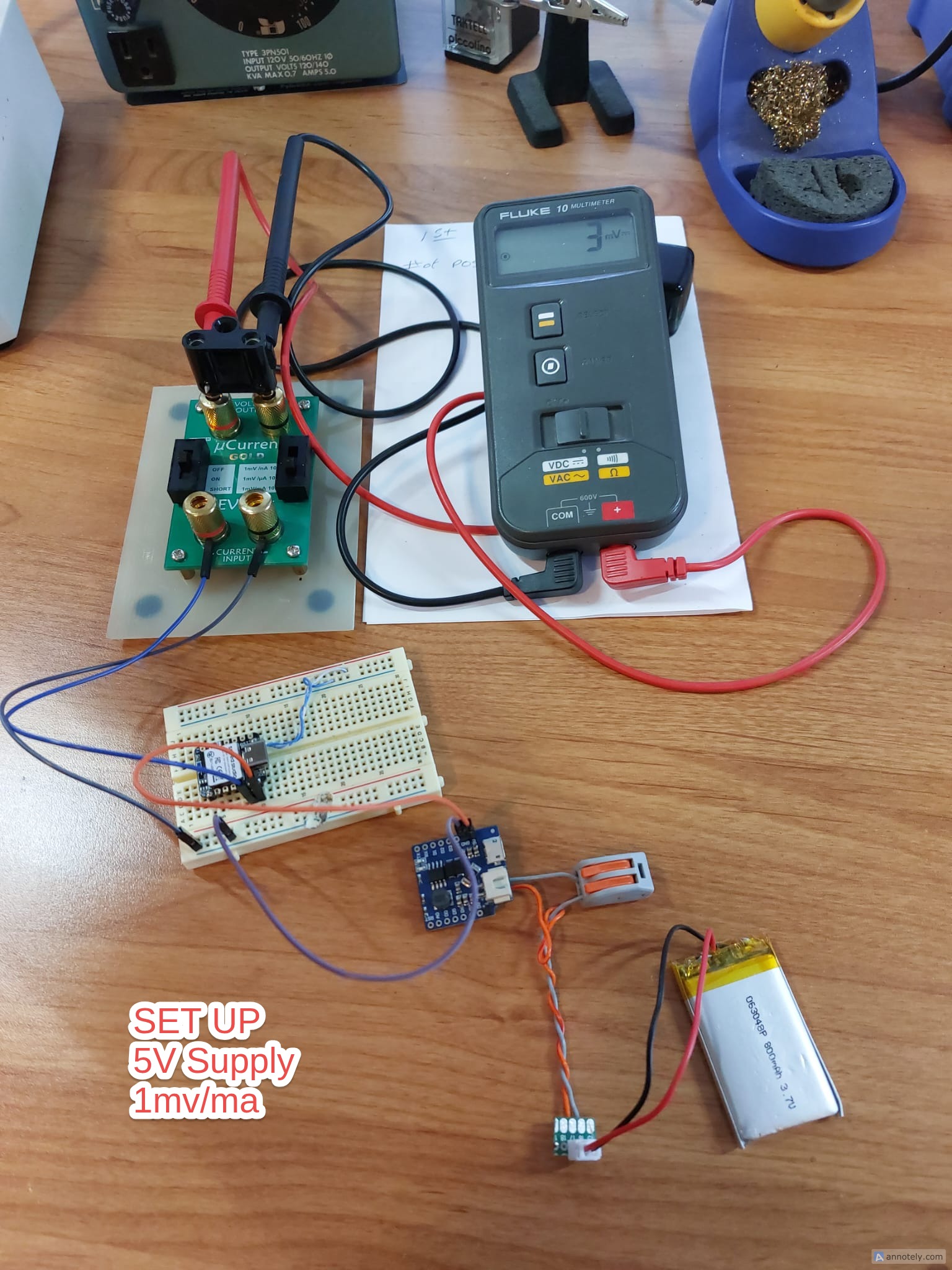
I’m new to the XIAO nrf52840 but not low power design. I am using a XIAO nrf52850 plain (non-sense) board as a BLE beacon. I’m powering it using a 5V supply to the board (not via USB). I am measuring current from the supply using a uCurrent Gold.
With the board powered from the 5V supply, its uses a minimum of 3ma of current. This is odd since I would have assumed the LDO on the board would be super efficient. If I put the SOC into power-down mode deep sleep, it still draws 1ma from the 5V supply.
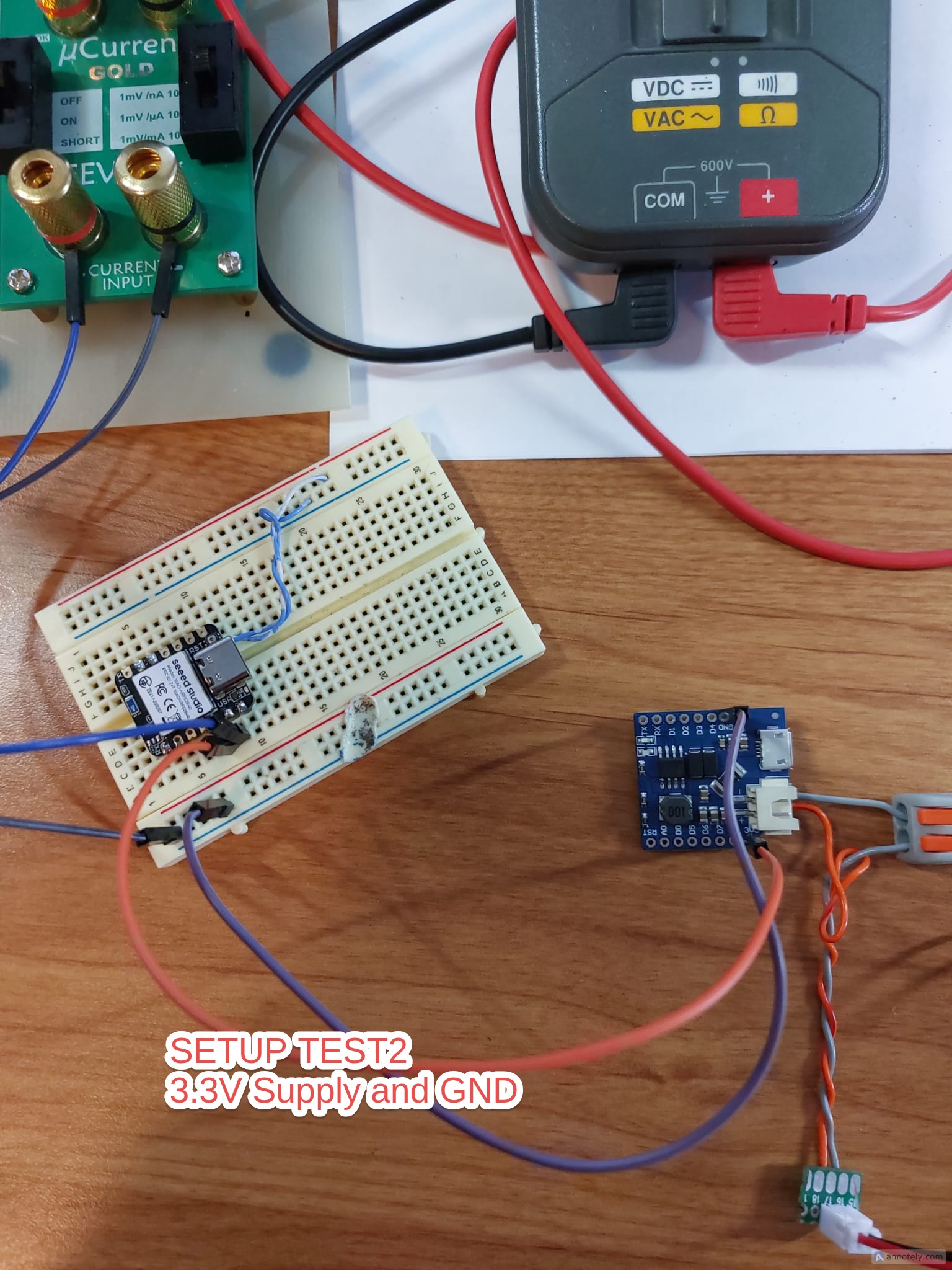
If I instead bypass the on-board LDO and supply 3.3V to the board, it draws only 4 uA when idle and about 25 uA from the 3.3V supply when it sends out the beacon. This is what I would expect from the board.
The schematic shows U6 as the 3.3V LDO without any part information. I find it hard to believe that this part would consume so much power.
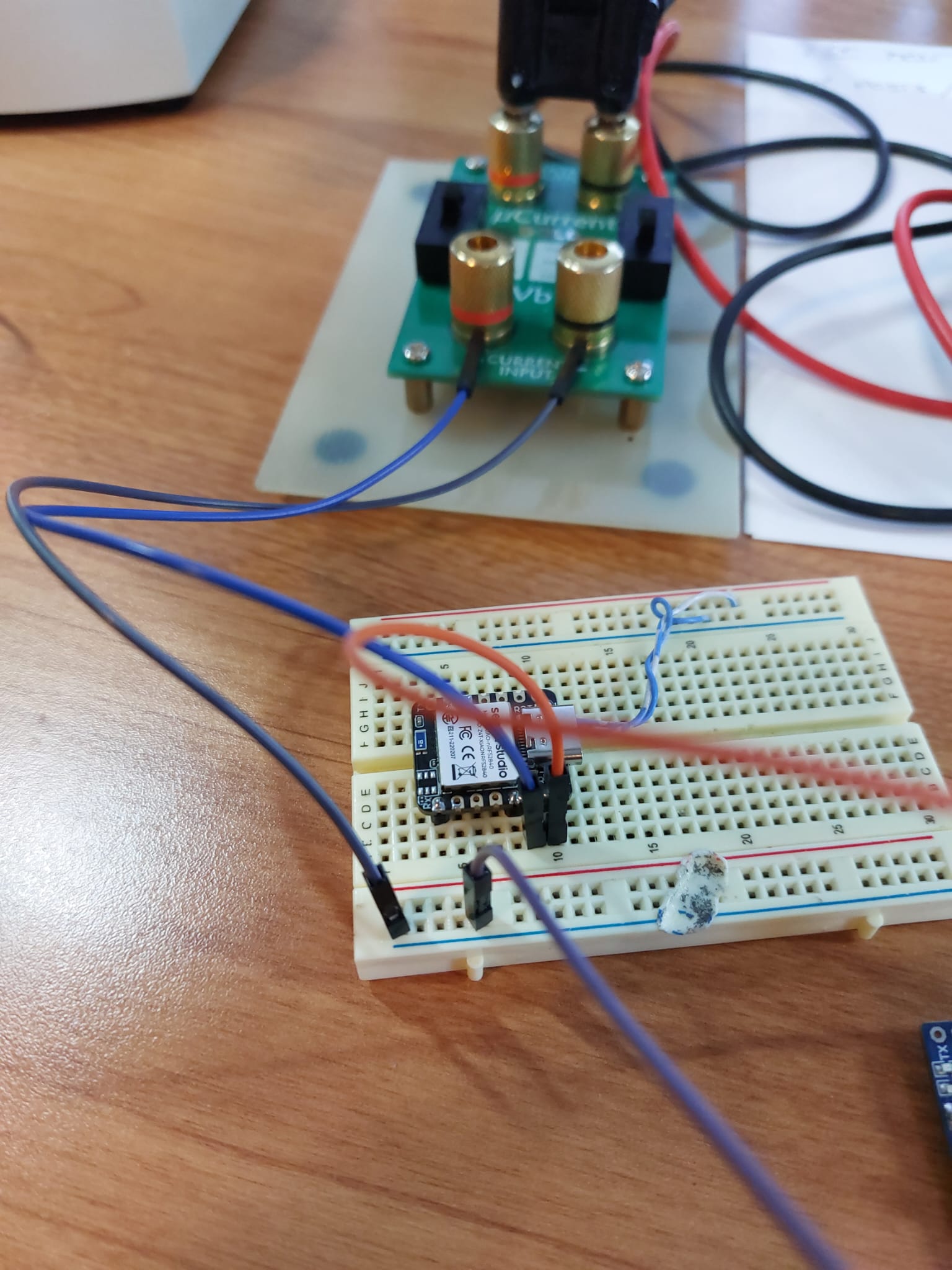
Can you post a pic , how you have it connected. WHich BSP are you compiling with ? and IDE? We have used the PPK2 for most if not all the measurements. You right in there on it with 3.3v
are you using a coin cell battery ? Which one?
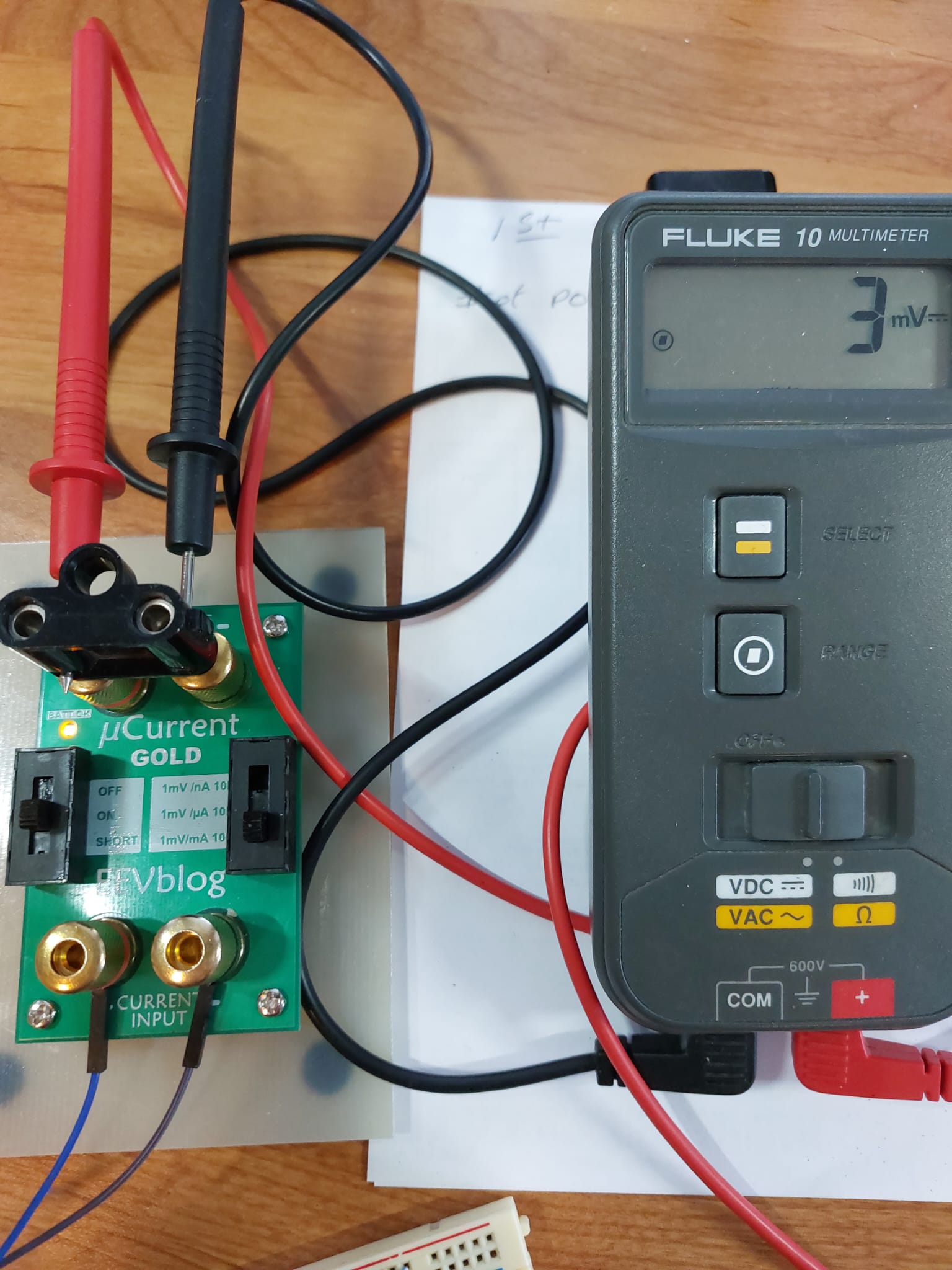
5V is connected and GND with the uCurrent Gold set connected and set to 1mv/ma. The board is running code that does nothing. It simply sleeps. The board is drawing 3ma when powered on the 5V pin.
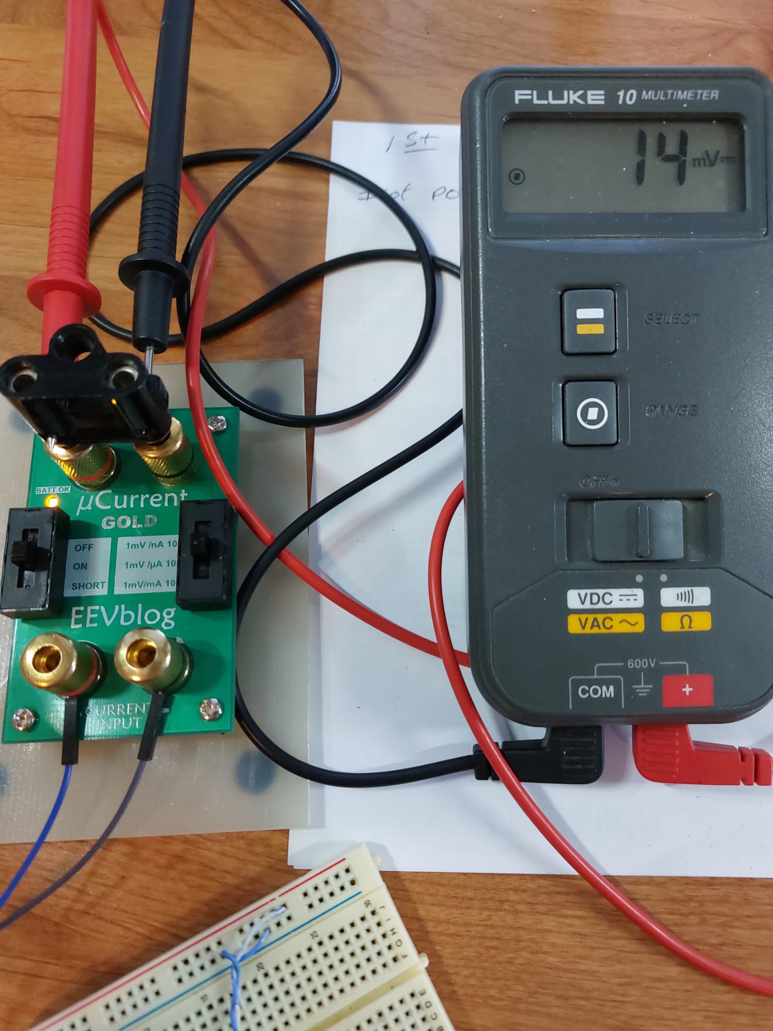
In the second test, the board is connected to 3.3V pin and GND. The uCurrent Gold is set to read 1mv/uA. The board is drawing between 14/15 uA when powered on the 3.3V pin.
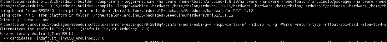
Code is compiled using gcc, arduino IDE level 0 (release) .
1 ma is still not great, but in my case, I’m seeing 3ma on the 5V supply and that translates into more like a 5ma load on the battery which is driving a small boost converter.
I was hoping to be able to power with just 5V as I have other components in the design that require the 5V rail.
So Have you tried to Roll back the BSP to the 1.1.1 variety and test again?
more to rule out the softdevice and also I believe it’s not the TI part anymore but I may be wrong? this was an earlier conversation years ago, but SMH
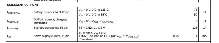
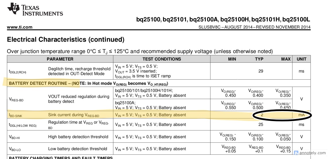
Took a closer look at the TI datasheet and indeed, the battery detection algorithm does use 2ma when the chip tries to detect the presence of a battery.
This coupled with the other 1ma quiescent current usage adds up to the 3ma I’m seeing.