Help with spi with spi conection

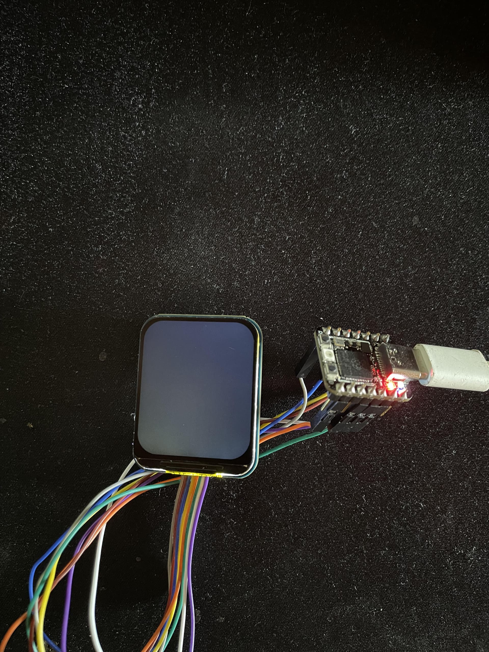
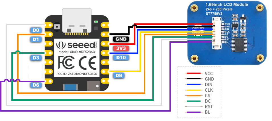
I have a problem, I am using the Xiao rp2040 board to run a waveshares 1.69 inch screen that uses spi but I am using a very similar code that I found on the speedstudio page but it is the xiao nrf52840. I attach the diagram that I study using

This is a part of the programming of the screen releases that I imagine initializes it. But it caught my attention that it declares some pins and I don’t know if the rp2040 chip is located in a different way than most likely yes.

///////////////////////////////////////////////////////
#ifndef ST7789V2_H

#define ST7789V2_H

#include <Arduino.h>

#include “stdio.h”

#include “fonts.h”

#include <SPI.h>

#if defined(ARDUINO_SEEED_XIAO_NRF52840_SENSE) || defined(ARDUINO_SEEED_XIAO_NRF52840)

#include <avr/dtostrf.h>

#endif

#define RST_PIN D0

#define DC_PIN D3

#define BL_PIN D6

#define CS_PIN D1

#define LCD_WIDTH 240 //LCD width

#define LCD_HEIGHT 280 //LCD height

#define DEV_DEBUG 1

#if DEV_DEBUG

#define Debug(__info,…) printf("Debug : " __info,##VA_ARGS)

#else

#define DEBUG(__info,…)

#endif

/**

  • The size of the point

**/

typedef enum {

DOT_PIXEL_1X1  = 1,   // 1 x 1

DOT_PIXEL_2X2  ,    // 2 X 2

DOT_PIXEL_3X3  ,    // 3 X 3

DOT_PIXEL_4X4  ,    // 4 X 4

DOT_PIXEL_5X5  ,    // 5 X 5

DOT_PIXEL_6X6  ,    // 6 X 6

DOT_PIXEL_7X7  ,    // 7 X 7

DOT_PIXEL_8X8  ,    // 8 X 8

} DOT_PIXEL;

#define DOT_PIXEL_DFT DOT_PIXEL_1X1 //Default dot pilex

/**

  • Point size fill style

**/

typedef enum {

DOT_FILL_AROUND  = 1,   // dot pixel 1 x 1

DOT_FILL_RIGHTUP  ,     // dot pixel 2 X 2

} DOT_STYLE;

#define DOT_STYLE_DFT DOT_FILL_AROUND //Default dot pilex

/**

  • Line style, solid or dashed

**/

typedef enum {

LINE_STYLE_SOLID = 0,

LINE_STYLE_DOTTED,

} LINE_STYLE;

/**

  • Whether the graphic is filled

**/

typedef enum {

DRAW_FILL_EMPTY = 0,

DRAW_FILL_FULL,

} DRAW_FILL;

/**

  • image color

**/

#define WHITE 0xFFFF

#define BLACK 0x0000

#define BLUE 0x001F

#define BRED 0XF81F

#define GRED 0XFFE0

#define GBLUE 0X07FF

#define RED 0xF800

#define MAGENTA 0xF81F

#define GREEN 0x07E0

#define CYAN 0x7FFF

#define YELLOW 0xFFE0

#define BROWN 0XBC40

#define BRRED 0XFC07

#define GRAY 0X8430

#define DARKBLUE 0X01CF

#define LIGHTBLUE 0X7D7C

#define GRAYBLUE 0X5458

#define LIGHTGREEN 0X841F

#define LGRAY 0XC618

#define LGRAYBLUE 0XA651

#define LBBLUE 0X2B12

/**

  • Display rotate

**/

#define ROTATE_0 0

#define ROTATE_90 90

#define ROTATE_180 180

#define ROTATE_270 270

#define MIRROR_NONE 0x00

#define MIRROR_HORIZONTAL 0x01

#define MIRROR_VERTICAL 0x02

#define MIRROR_ORIGIN 0x03

class st7789v2{

protected:

    uint8_t spi_cs, spi_dc, spi_rst, spi_bl;

    uint16_t ROTA = ROTATE_0, MIRR = MIRROR_NONE;

private:

    void WriteReg(uint8_t data);

    void WriteData_Byte(uint8_t data);

    void WriteData_Word(uint16_t data);

    void DrawChar(int16_t Xpoint, int16_t Ypoint, const char Acsii_Char, sFONT* Font, int16_t Color_Background, int16_t Color_Foreground);

public:

    // bool horizontal = false;

    uint8_t mirror = MIRROR_NONE;

    void Init(uint8_t cs = CS_PIN, uint8_t dc = DC_PIN, uint8_t rst = RST_PIN, uint8_t bl = BL_PIN);

    void SetBacklight(uint16_t Value);

    void Reset(void);

    void SetCursor(uint16_t Xstart, uint16_t Ystart, uint16_t Xend, uint16_t Yend);

    void Clear(uint16_t Color);

    void ClearWindow(uint16_t Xstart, uint16_t Ystart, uint16_t Xend, uint16_t Yend, uint16_t color);

    void SetWindowColor(uint16_t Xstart, uint16_t Ystart, uint16_t Xend, uint16_t Yend, uint16_t Color);

    void SetUWORD(uint16_t x, uint16_t y, uint16_t Color);

    void SetRotate(uint16_t Rotate);

    void SetMirroring(uint8_t mirror);

    void SetPixel(uint16_t Xpoint, uint16_t Ypoint, uint16_t Color);

    void DrawPoint( uint16_t Xpoint, uint16_t Ypoint, uint16_t Color, DOT_PIXEL Dot_Pixel, DOT_STYLE Dot_FillWay);

    void DrawLine(uint16_t Xstart, uint16_t Ystart, uint16_t Xend, uint16_t Yend, uint16_t Color, DOT_PIXEL Line_width, LINE_STYLE Line_Style);

    void DrawRectangle(uint16_t Xstart, uint16_t Ystart, uint16_t Xend, uint16_t Yend, uint16_t Color, DOT_PIXEL Line_width, DRAW_FILL Filled);

    void DrawCircle(uint16_t X_Center, uint16_t Y_Center, uint16_t Radius, uint16_t Color, DOT_PIXEL Line_width, DRAW_FILL Draw_Fill);

    void DrawString_EN(int16_t Xstart, int16_t Ystart, const char * pString, sFONT* Font, int16_t Color_Background, int16_t Color_Foreground);

    void DrawNum(int16_t Xpoint, int16_t Ypoint, int32_t Nummber, sFONT* Font, int16_t Color_Background, int16_t Color_Foreground);

    void DrawFloatNum(int16_t Xpoint, int16_t Ypoint, double Nummber,  int8_t Decimal_Point, sFONT* Font, int16_t Color_Background, int16_t Color_Foreground);

    void DrawImage(const unsigned char *image, int16_t xStart, int16_t yStart, int16_t W_Image, int16_t H_Image);

};

//////////////////////////////////////////////////
Please help, I need to know and get the screen to work but I don’t know why it doesn’t work. I don’t know if it’s the code or the hardware or both.

Its the pin numbers… follow this link

It’s not working, I don’t know why I used the same connection as the schematic and I did what you said but still nothing. OMG I have never had so many problems with SPI

Hi there,
You sound a little tightly wound , Relax it’s only code…
Which BSP are you using?
first point is post it properly using the code tags above (</>) paste it in there. I went ahead and did that for you, also I see a NuMMBER of spelling errors are those intentionally?
second,
It’s SPI so there are a number of basic rules and methods to test and verify your assumptions.
add this to your code,

//Find the default SPI pins for your board
//Make sure you have the right board selected in Tools > Boards
void setup() {
  // put your setup code here, to run once:
  Serial.begin(115200);
  Serial.print("MOSI: ");
  Serial.println(MOSI);
  Serial.print("MISO: ");
  Serial.println(MISO);
  Serial.print("SCK: ");
  Serial.println(SCK);
  Serial.print("SS: ");
  Serial.println(SS);  
}

Posting a snippet isn’t good enough , you need the complete code, beware if you are just being a Cut&Paste Jockey and copying from the internet, some of the characters are not ANSI spec, i.e. " quote marks for example. watch out for that.

///////////////////////////////////////////////////////
#ifndef ST7789V2_H
#define ST7789V2_H
#include <Arduino.h>
#include “stdio.h”
#include “fonts.h”

#include <SPI.h>

#if defined(ARDUINO_SEEED_XIAO_NRF52840_SENSE) || defined(ARDUINO_SEEED_XIAO_NRF52840)
#include <avr/dtostrf.h>
#endif
#define RST_PIN D0
#define DC_PIN D3
#define BL_PIN D6

#define CS_PIN D1

#define LCD_WIDTH 240 //LCD width
#define LCD_HEIGHT 280 //LCD height
#define DEV_DEBUG 1
#if DEV_DEBUG
#define Debug(__info,…) printf("Debug : " __info,##VA_ARGS)
#else
#define DEBUG(__info,…)
#endif
/**
The size of the point
**/
typedef enum {
DOT_PIXEL_1X1  = 1,   // 1 x 1
DOT_PIXEL_2X2  ,    // 2 X 2
DOT_PIXEL_3X3  ,    // 3 X 3
DOT_PIXEL_4X4  ,    // 4 X 4
DOT_PIXEL_5X5  ,    // 5 X 5
DOT_PIXEL_6X6  ,    // 6 X 6
DOT_PIXEL_7X7  ,    // 7 X 7
DOT_PIXEL_8X8  ,    // 8 X 8
} DOT_PIXEL;
#define DOT_PIXEL_DFT DOT_PIXEL_1X1 //Default dot pilex
/**
Point size fill style
**/
typedef enum {
DOT_FILL_AROUND  = 1,   // dot pixel 1 x 1
DOT_FILL_RIGHTUP  ,     // dot pixel 2 X 2
} DOT_STYLE;
#define DOT_STYLE_DFT DOT_FILL_AROUND //Default dot pilex
/**
Line style, solid or dashed
**/
typedef enum {
LINE_STYLE_SOLID = 0,
LINE_STYLE_DOTTED,
} LINE_STYLE;
/**
Whether the graphic is filled
**/
typedef enum {
DRAW_FILL_EMPTY = 0,
DRAW_FILL_FULL,
} DRAW_FILL;
/**
image color
**/
#define WHITE 0xFFFF
#define BLACK 0x0000
#define BLUE 0x001F
#define BRED 0XF81F
#define GRED 0XFFE0
#define GBLUE 0X07FF
#define RED 0xF800
#define MAGENTA 0xF81F
#define GREEN 0x07E0
#define CYAN 0x7FFF
#define YELLOW 0xFFE0
#define BROWN 0XBC40
#define BRRED 0XFC07
#define GRAY 0X8430
#define DARKBLUE 0X01CF
#define LIGHTBLUE 0X7D7C
#define GRAYBLUE 0X5458
#define LIGHTGREEN 0X841F
#define LGRAY 0XC618
#define LGRAYBLUE 0XA651
#define LBBLUE 0X2B12
/**
Display rotate
**/
#define ROTATE_0 0
#define ROTATE_90 90
#define ROTATE_180 180
#define ROTATE_270 270
#define MIRROR_NONE 0x00
#define MIRROR_HORIZONTAL 0x01
#define MIRROR_VERTICAL 0x02
#define MIRROR_ORIGIN 0x03
class st7789v2{
protected:
    uint8_t spi_cs, spi_dc, spi_rst, spi_bl;
    uint16_t ROTA = ROTATE_0, MIRR = MIRROR_NONE;
private:
    void WriteReg(uint8_t data);
    void WriteData_Byte(uint8_t data);
    void WriteData_Word(uint16_t data);
    void DrawChar(int16_t Xpoint, int16_t Ypoint, const char Acsii_Char, sFONT* Font, int16_t Color_Background, int16_t Color_Foreground);
public:
    // bool horizontal = false;
    uint8_t mirror = MIRROR_NONE;
    void Init(uint8_t cs = CS_PIN, uint8_t dc = DC_PIN, uint8_t rst = RST_PIN, uint8_t bl = BL_PIN);
    void SetBacklight(uint16_t Value);
    void Reset(void);
    void SetCursor(uint16_t Xstart, uint16_t Ystart, uint16_t Xend, uint16_t Yend);
    void Clear(uint16_t Color);
    void ClearWindow(uint16_t Xstart, uint16_t Ystart, uint16_t Xend, uint16_t Yend, uint16_t color);
    void SetWindowColor(uint16_t Xstart, uint16_t Ystart, uint16_t Xend, uint16_t Yend, uint16_t Color);
    void SetUWORD(uint16_t x, uint16_t y, uint16_t Color);
    void SetRotate(uint16_t Rotate);
    void SetMirroring(uint8_t mirror);
    void SetPixel(uint16_t Xpoint, uint16_t Ypoint, uint16_t Color);
    void DrawPoint( uint16_t Xpoint, uint16_t Ypoint, uint16_t Color, DOT_PIXEL Dot_Pixel, DOT_STYLE Dot_FillWay);
    void DrawLine(uint16_t Xstart, uint16_t Ystart, uint16_t Xend, uint16_t Yend, uint16_t Color, DOT_PIXEL Line_width, LINE_STYLE Line_Style);
    void DrawRectangle(uint16_t Xstart, uint16_t Ystart, uint16_t Xend, uint16_t Yend, uint16_t Color, DOT_PIXEL Line_width, DRAW_FILL Filled);
    void DrawCircle(uint16_t X_Center, uint16_t Y_Center, uint16_t Radius, uint16_t Color, DOT_PIXEL Line_width, DRAW_FILL Draw_Fill);
    void DrawString_EN(int16_t Xstart, int16_t Ystart, const char * pString, sFONT* Font, int16_t Color_Background, int16_t Color_Foreground);
    void DrawNum(int16_t Xpoint, int16_t Ypoint, int32_t Nummber, sFONT* Font, int16_t Color_Background, int16_t Color_Foreground);
    void DrawFloatNum(int16_t Xpoint, int16_t Ypoint, double Nummber,  int8_t Decimal_Point, sFONT* Font, int16_t Color_Background, int16_t Color_Foreground);
    void DrawImage(const unsigned char *image, int16_t xStart, int16_t yStart, int16_t W_Image, int16_t H_Image);
};

Start with this and go again. Lots of smart folks on here to help, and a second set of eyes.
It would be good also to say what it is your trying to accomplish. The most people who get help and find success are those who give more complete information. ie. what they have tried and what the errors were. I don’t see anything but a messy post with "here’s my junk , Fix it " Please.
That display and Xiao work very well.BTW
HTH
GL :slight_smile: PJ
:v:

Ok I’ll try to be much more specific. I’m trying to put a red background on this screen that uses the ST7789 driver but when I enter the code it just doesn’t do anything. I suspect they are the pins since the CS pin is located on D7 but the driver code puts it on D0. I don’t know if at the hardware level the D0 pin is also CS. The screen is functional because if I connect it to an Arduino it works but when using it on this xiaorp2040 board it doesn’t work. I attach the code, maybe I have an error and I don’t realize it.
RED COLOR CODE IN THE BACKGROUND

#include <st7789v2.h>
#include "SPI.h"

st7789v2 lcd;

void setup() {
  Serial.begin(115200);
  Serial.print("MOSI: ");
  Serial.println(MOSI);
  Serial.print("MISO: ");
  Serial.println(MISO);
  Serial.print("SCK: ");
  Serial.println(SCK);
  Serial.print("SS: ");
  Serial.println(SS); 
  // put your setup code here, to run once:
  lcd.Init();
  lcd.SetBacklight(100);
  lcd.Clear(RED);
}

void loop() {
  // put your main code here, to run repeatedly:
  
}

STVST7789 CODE

#ifndef __ST7789V2_H__
#define __ST7789V2_H__

#include <Arduino.h>
#include "stdio.h"
#include "fonts.h"
#include <SPI.h>

#if defined(ARDUINO_SEEED_XIAO_NRF52840_SENSE) || defined(ARDUINO_SEEED_XIAO_NRF52840)
#include <avr/dtostrf.h>
#endif

#define RST_PIN D0
#define DC_PIN  D3
#define BL_PIN  D6
#define CS_PIN  D1

#define LCD_WIDTH   240 //LCD width
#define LCD_HEIGHT  280 //LCD height

#define DEV_DEBUG 1
#if DEV_DEBUG
  #define Debug(__info,...) printf("Debug : " __info,##__VA_ARGS__)
#else
  #define DEBUG(__info,...)  
#endif

/**
 * The size of the point
**/
typedef enum {
    DOT_PIXEL_1X1  = 1,   // 1 x 1
    DOT_PIXEL_2X2  ,    // 2 X 2
    DOT_PIXEL_3X3  ,    // 3 X 3
    DOT_PIXEL_4X4  ,    // 4 X 4
    DOT_PIXEL_5X5  ,    // 5 X 5
    DOT_PIXEL_6X6  ,    // 6 X 6
    DOT_PIXEL_7X7  ,    // 7 X 7
    DOT_PIXEL_8X8  ,    // 8 X 8
} DOT_PIXEL;
#define DOT_PIXEL_DFT  DOT_PIXEL_1X1  //Default dot pilex

/**
 * Point size fill style
**/
typedef enum {
    DOT_FILL_AROUND  = 1,   // dot pixel 1 x 1
    DOT_FILL_RIGHTUP  ,     // dot pixel 2 X 2
} DOT_STYLE;
#define DOT_STYLE_DFT  DOT_FILL_AROUND  //Default dot pilex

/**
 * Line style, solid or dashed
**/
typedef enum {
    LINE_STYLE_SOLID = 0,
    LINE_STYLE_DOTTED,
} LINE_STYLE;

/**
 * Whether the graphic is filled
**/
typedef enum {
    DRAW_FILL_EMPTY = 0,
    DRAW_FILL_FULL,
} DRAW_FILL;

/**
 * image color
**/
#define WHITE         0xFFFF
#define BLACK         0x0000    
#define BLUE          0x001F  
#define BRED          0XF81F
#define GRED          0XFFE0
#define GBLUE         0X07FF
#define RED           0xF800
#define MAGENTA       0xF81F
#define GREEN         0x07E0
#define CYAN          0x7FFF
#define YELLOW        0xFFE0
#define BROWN         0XBC40 
#define BRRED         0XFC07 
#define GRAY          0X8430 
#define DARKBLUE      0X01CF  
#define LIGHTBLUE     0X7D7C   
#define GRAYBLUE      0X5458 
#define LIGHTGREEN    0X841F 
#define LGRAY         0XC618 
#define LGRAYBLUE     0XA651
#define LBBLUE        0X2B12

/**
 * Display rotate
**/
#define ROTATE_0            0
#define ROTATE_90           90
#define ROTATE_180          180
#define ROTATE_270          270

#define MIRROR_NONE        0x00
#define MIRROR_HORIZONTAL  0x01
#define MIRROR_VERTICAL    0x02
#define MIRROR_ORIGIN      0x03

class st7789v2{
    protected:
        uint8_t spi_cs, spi_dc, spi_rst, spi_bl;
        uint16_t ROTA = ROTATE_0, MIRR = MIRROR_NONE;
    private:
        void WriteReg(uint8_t data);
        void WriteData_Byte(uint8_t data);
        void WriteData_Word(uint16_t data);
        void DrawChar(int16_t Xpoint, int16_t Ypoint, const char Acsii_Char, sFONT* Font, int16_t Color_Background, int16_t Color_Foreground);


    public:
        // bool horizontal = false;
        uint8_t mirror = MIRROR_NONE;
        void Init(uint8_t cs = CS_PIN, uint8_t dc = DC_PIN, uint8_t rst = RST_PIN, uint8_t bl = BL_PIN);
        void SetBacklight(uint16_t Value);
        void Reset(void);
        void SetCursor(uint16_t Xstart, uint16_t Ystart, uint16_t Xend, uint16_t Yend);
        void Clear(uint16_t Color);
        void ClearWindow(uint16_t Xstart, uint16_t Ystart, uint16_t Xend, uint16_t Yend, uint16_t color);
        void SetWindowColor(uint16_t Xstart, uint16_t Ystart, uint16_t Xend, uint16_t Yend, uint16_t Color);
        void SetUWORD(uint16_t x, uint16_t y, uint16_t Color);
        void SetRotate(uint16_t Rotate);
        void SetMirroring(uint8_t mirror);
        void SetPixel(uint16_t Xpoint, uint16_t Ypoint, uint16_t Color);
        void DrawPoint( uint16_t Xpoint, uint16_t Ypoint, uint16_t Color, DOT_PIXEL Dot_Pixel, DOT_STYLE Dot_FillWay);
        void DrawLine(uint16_t Xstart, uint16_t Ystart, uint16_t Xend, uint16_t Yend, uint16_t Color, DOT_PIXEL Line_width, LINE_STYLE Line_Style);
        void DrawRectangle(uint16_t Xstart, uint16_t Ystart, uint16_t Xend, uint16_t Yend, uint16_t Color, DOT_PIXEL Line_width, DRAW_FILL Filled);
        void DrawCircle(uint16_t X_Center, uint16_t Y_Center, uint16_t Radius, uint16_t Color, DOT_PIXEL Line_width, DRAW_FILL Draw_Fill);
        void DrawString_EN(int16_t Xstart, int16_t Ystart, const char * pString, sFONT* Font, int16_t Color_Background, int16_t Color_Foreground);
        void DrawNum(int16_t Xpoint, int16_t Ypoint, int32_t Nummber, sFONT* Font, int16_t Color_Background, int16_t Color_Foreground);
        void DrawFloatNum(int16_t Xpoint, int16_t Ypoint, double Nummber,  int8_t Decimal_Point, sFONT* Font, int16_t Color_Background, int16_t Color_Foreground);
        void DrawImage(const unsigned char *image, int16_t xStart, int16_t yStart, int16_t W_Image, int16_t H_Image);
};


#endif

I would appreciate your help or maybe you have code that works because it doesn’t seem to work.
Screen image


Connection diagram i use. This diagram is for an NRF52840 board, maybe that’s where my problems come from.

are you pulling the reset line in the correct direction?

Hi Engenier09,
Although not exactly the same, the following sketch is working. Please refer to it.

#include <Adafruit_GFX.h>    // Core graphics library
#include <Adafruit_ST7735.h> // Hardware-specific library for ST7735
#include "Fonts/FreeSans9pt7b.h"
#include "Fonts/FreeSerif9pt7b.h"
#include <SPI.h>

#define TFT_CS        D7  // Chip Select
#define TFT_RST       D3  // Or set to -1 and connect to Arduino RESET pin
#define TFT_DC        D2  // Data/Command
#define TFT_MOSI      D10 // Data out
#define TFT_SCLK      D8  // Clock out
#define PIN_LED       17  // RED

// For ST7735-based displays, we will use this call
Adafruit_ST7735 tft = Adafruit_ST7735(TFT_CS, TFT_DC, TFT_MOSI, TFT_SCLK, TFT_RST);

void setup() {
  Serial.begin(115200);
//  while (!Serial) { ; }

  //LEDの設定
  pinMode(PIN_LED, OUTPUT);
  digitalWrite(PIN_LED, HIGH);

  Serial.println(F("Hello! ST7735 TFT Test"));

  // use this initializer (uncomment) if using a 0.96" 160x80 TFT:
  tft.initR(INITR_MINI160x80);  // Init ST7735S mini display

  // SPI speed defaults to SPI_DEFAULT_FREQ(32MHz) defined in the library, you can override it here
  // Note that speed allowable depends on chip and quality of wiring, if you go too fast, you
  // may end up with a black screen some times, or all the time.
  tft.setSPISpeed(12000000UL); //Adafruit_SPITFT.cpp

  Serial.println(F("Initialized"));

  tft.setCursor(0, 15);
  tft.fillScreen(ST77XX_BLACK);
  tft.setTextColor(ST77XX_WHITE);
  tft.setFont(&FreeSans9pt7b);  
  tft.setRotation(3);
  tft.setTextColor(ST77XX_RED);
  tft.println("Hello....");
  tft.setTextColor(ST77XX_BLUE);
  tft.println("....1234567890");

  delay(2000);

  
}

void loop() {
  tft.fillScreen(ST77XX_BLACK);    
  tft.setCursor(0, 15);
  tft.setTextColor(ST77XX_WHITE);
  tft.print(millis());
  tft.setTextColor(ST77XX_GREEN);
  tft.println("  mS"); 
  tft.setCursor(0, 31);
  tft.setTextColor(ST77XX_WHITE);    
  tft.print(micros());
  tft.setTextColor(ST77XX_GREEN);  
  tft.println("  uS");
}
2 Likes

OMG, WORKS THANKS!
Now I can use de LCD.