Hi all, I have a Grove Voltage Divider that I’m using to measure the battery percentage of a 3s LiPo battery but I’m receiving readings that are both inconsistent with my voltmeter (showing 12V+ input when it should be 11-12V) and unstable (frequent wild outliers plus a weird “cliff” where the voltage readings drop by ~1V for some period of time then go back up again). Voltage divider setting is 10 as when I had it on 3 it kept tripping the over-voltage red light, claiming that the voltage was 13.2V+ (voltmeter claimed it was 12.4V, exactly as the balance charger said as well).
This data comes from a simple Python script very similar to the example:
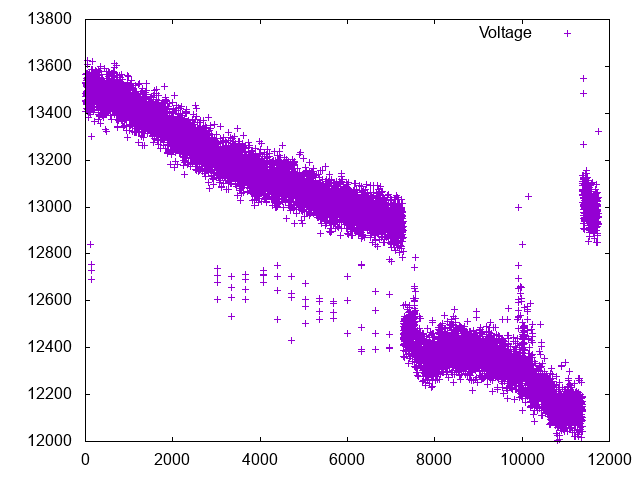
The 3s LiPo battery began fully charged at 12.4V (so immediately the first set of readings are not plausible), and ran continuously drawing current into a motor for a few hours, depleting down to 11.2V toward the last samples in the dataset.
Any insights here or anything I could try to repair these readings? Especially the strange cliff is going to be very difficult to work around as I won’t be able to know if I’m experiencing one of those cliffs or whether I should adjust the result up or down.
We have described on the wiki interface that this product is not supported by the Raspberry Pi, to prove that it is not a problem with the program, do you have an Arduino platform that you can re-run to test it?
I do not have an Arduino to test, although I read the wiki page more along the lines of saying that the software wasn’t necessarily fully supported and test, but I assumed hardware wise there wouldn’t be any reason why the Grove HAT for the Pi would work differently for analog reads than the Arduino. That might be naive though, perhaps you have more insight into what exactly might be different and why that would affect this component?
I couldn’t say really, my experiment set-up was pretty simple and I didn’t detect any other interference anywhere. The basic configuration was a single LiPo 3S battery charged to full @ 12.4V, connected to a 40A ESC driving a powerful brushless motor at high (but not full) throttle, then just passively collecting data by running the script while I was off doing something else. The connections to everything appeared to be strong and stable, and the motor was being held in place in such a way that wouldn’t be physically interacting with the electronics / voltage divider.
Probably a stretch, but I did keep getting low voltage warnings on the Raspberry Pi because at the time I was using a USB battery pack that couldn’t provide stable 5V. I swapped that out and resumed the test with data I didn’t publish and strangely saw the cliff show up for only a few seconds then return to the normal linear voltage drop. In theory this could’ve affected the timing of when I was reading the voltage divider values resulting in noise, but this wouldn’t explain the cliff.
I can set-up another experiment and re-run soon just to see if I get consistent results. Though one of the things that gives me pause is why the voltage divider would think I’m getting 13V+ in the first place when two separate reliable measurement devices (my balance charger and voltmeter) both say it is exactly 12.4V. I also can’t understand why the readings are so sporadic even when things are working normally (e.g. around t=3000 a bunch of samples start randomly showing up in the 12.4-12.8V range even though the majority of samples are around 13.0-13.4V).
Am I allowed to ask why? Reading through the thread the maximum voltage you are trying to measure is 12.4 volts so I could you just use two resistors in series as a potential divider with the middle point connected to an analog input. For example, a 10K resistor in series with a 3K3 resistor would give you about 3.08V at the centre tap - nice to have a bit of headroom. I don’t know the resistance looking into the I/O lines but whatever it is, the 3.08V will be a little lower. If it’s high enough you may be fine with 100K and 33K drawing less current for the same job.
Sorry if I’ve completely misunderstood your post - won’t be the first time…