Grove rotary encoder incorrect readings

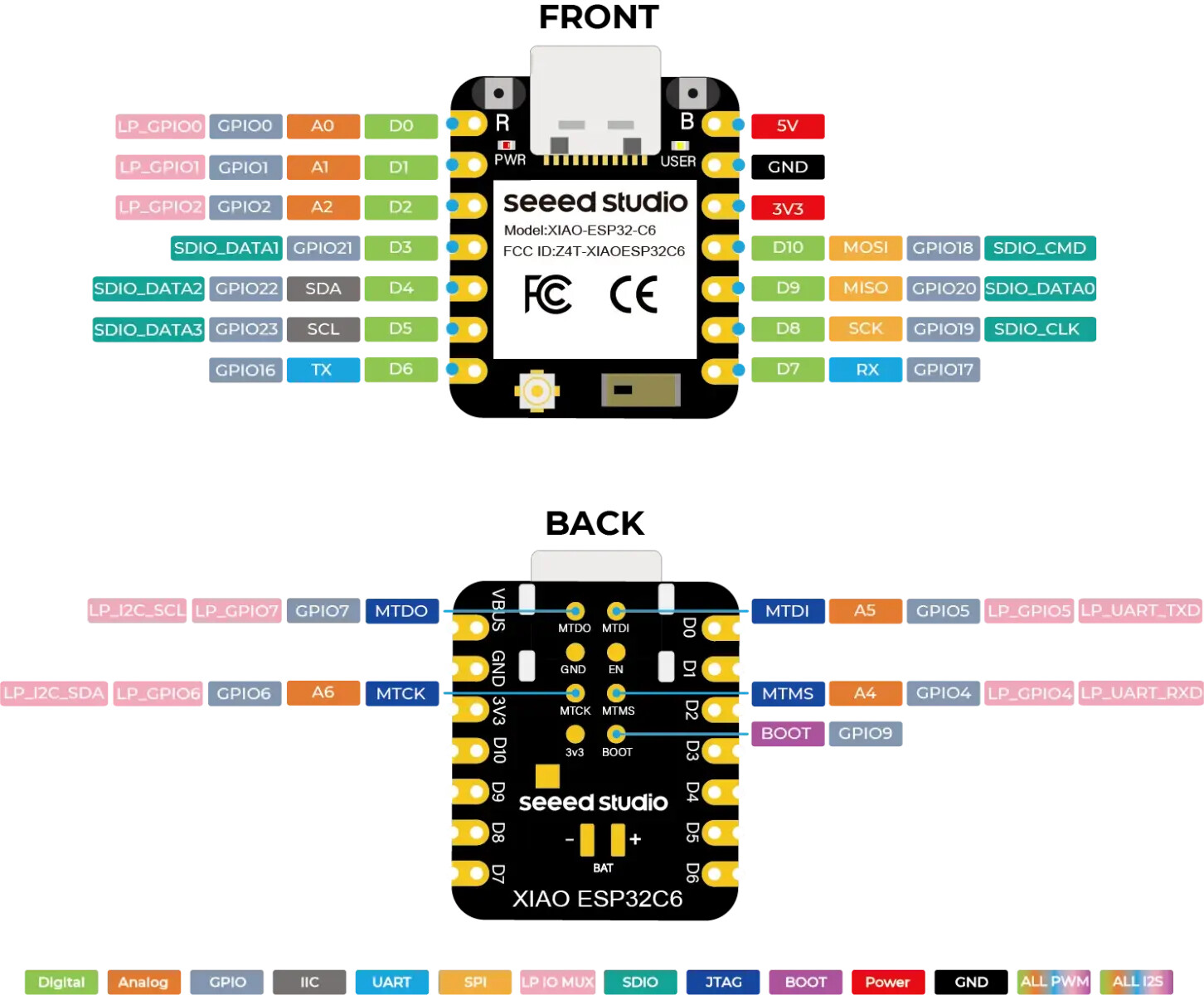
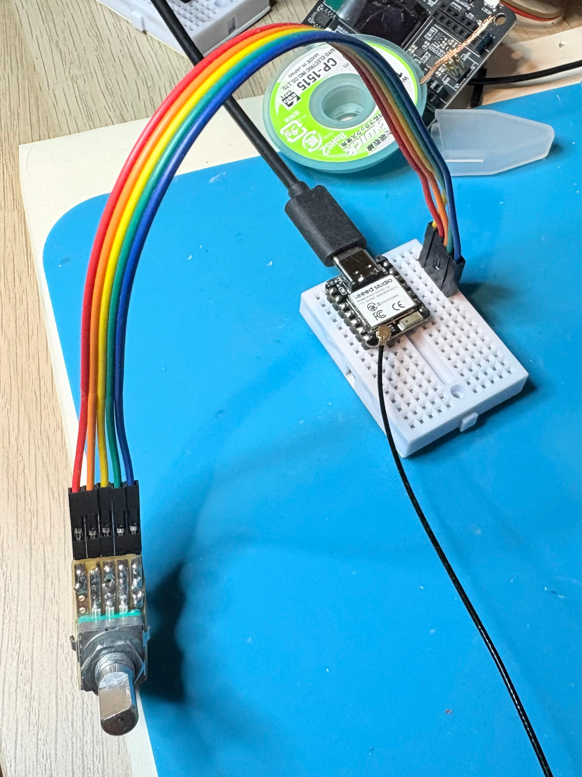
I am using the Grove rotary encoder with a Xiao ESP32C6 sitting on a XIAO Expansion Board.

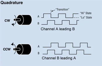
It mostly works, but I get an erroneous reading about 15% of the time (i.e. if I’m rotating solely up, I’ll get a number of erroneous down readings). They’re not extra readings, I still get one reading per detent.

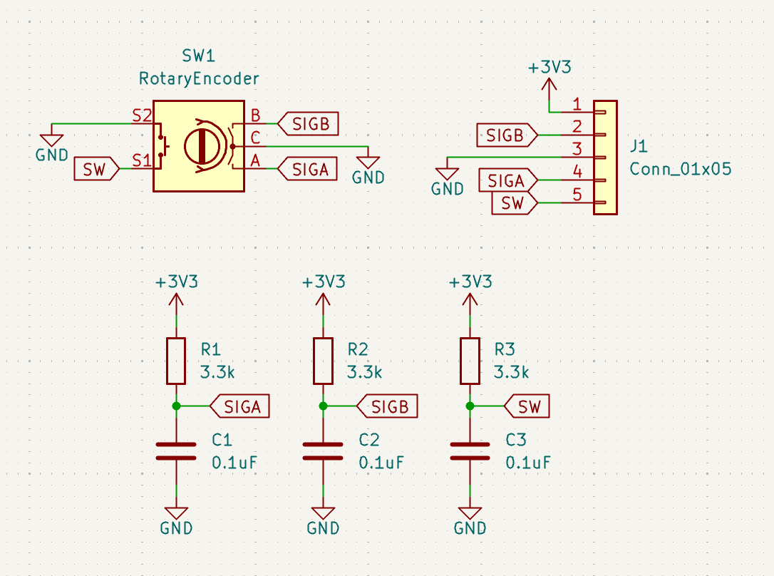
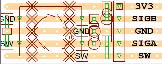
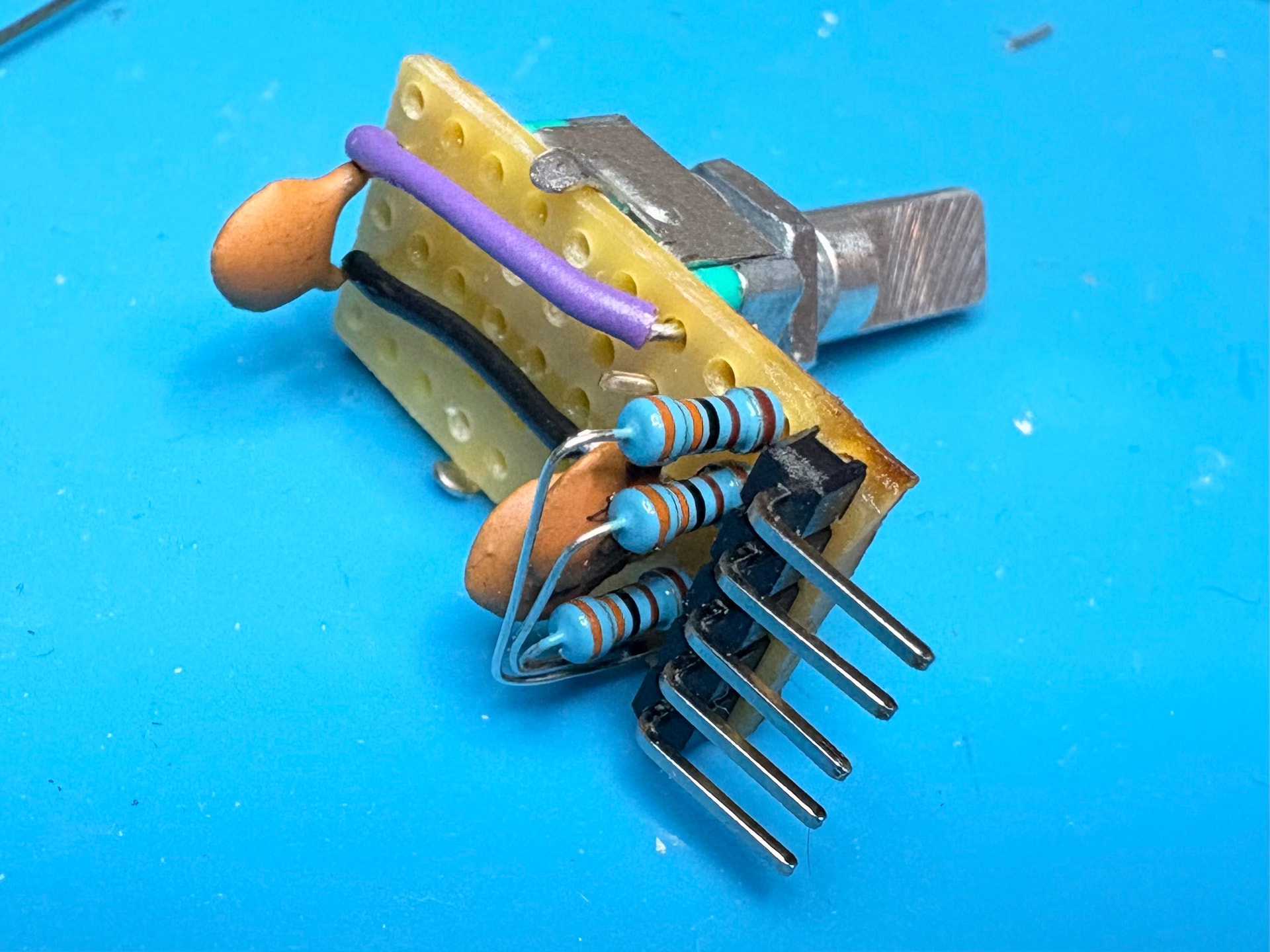
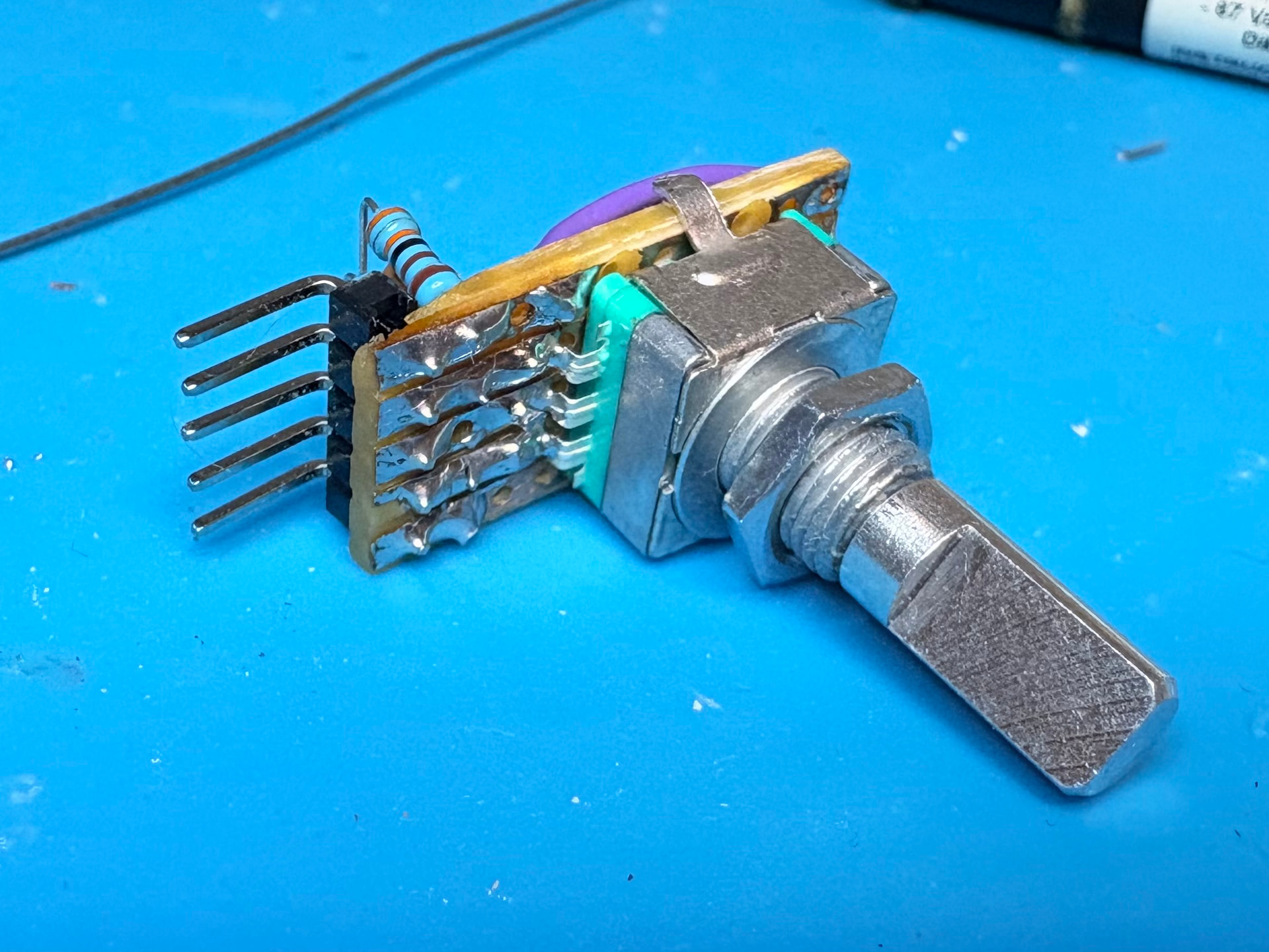
I’m wondering if I’m doing something wrong or if this is caused by the missing capacitors referenced in this post?

Wiring

As the expansion board only has one(!) digital pin on a Grove header, I’ve repurposed the Grove Serial port, which according to the schematic is connected to Xiao pins 7 (TX) and 8 (RX) and nothing else (besides the servo header that I’m not using).

TX is the 3rd pin on the grove connector and corresponds to SIGB on the encoder board.

RX is the 4th pin on the grove connector and corresponds to SIGA on the encoder board.

On the ESP32C6 module itself, pin 7 is indeed TX but is also GPIO16. Pin 8 is RX and is also GPIO17.

So I think it’s wired correctly:

Encoder SIGB→Grove pin 3→TX→GPIO16
Encoder SIGA→Grove pin 4→RX→GPIO17

Code

I’ve stripped it down to a simple test case that does nothing else, besides use a FreeRTOS queue to minimise the time spent in the ISR.

I’ve used INPUT and not INPUT_PULLUP as the encoder board has built-in pullups.

#include <Arduino.h>
#include <Wire.h>

#define PIN_ROTARY_A 17
#define PIN_ROTARY_B 16

#define ENCODER_DOWN 0
#define ENCODER_UP 1

QueueHandle_t encoderQueue;

volatile unsigned long lastEncoderChange = 0;

void setup(void)
{
  Serial.begin();
  Serial.print("started\n");

  pinMode(PIN_ROTARY_A, INPUT);
  pinMode(PIN_ROTARY_B, INPUT);

  if ((encoderQueue = xQueueCreate(500, 1)) == NULL) {
    Serial.println("unable to create queue");
    while (1) delay(1000);
  }

  attachInterrupt(digitalPinToInterrupt(PIN_ROTARY_A), encoderChange, RISING);
}

void ARDUINO_ISR_ATTR encoderChange()
{
  if ((millis() - lastEncoderChange) < 50)  // debounce time is 50ms
    return;

  // if (!digitalRead(PIN_ROTARY_A)) return;

  uint8_t direction;

  if (digitalRead(PIN_ROTARY_B) == HIGH) {
    direction = ENCODER_DOWN;
  }
  else {
    direction = ENCODER_UP;
  }

  if (xQueueSendToBackFromISR(encoderQueue, &direction, NULL) != pdPASS) {
    Serial.println("queue full");
    while (1) delay(1000);
  }
  lastEncoderChange = millis();
}

void loop()
{
  uint8_t direction;
  while (xQueueReceive(encoderQueue, &direction, 0) == pdPASS) {
    if (direction == ENCODER_DOWN) {
      Serial.println("down");
    }
    else {
      Serial.println("up");
    }
  }
}

I’ve tried swapping A and B and swapping RISING to FALLING and both. I’ve also tried using random other pin numbers to make sure my mapping above is correct (with other pins it either doesn’t react because the interrupt never triggers, or it always shows one direction, so I think I’m correct).

Thanks!

-davidc

You got thru the first part, that the expansion board bottom left grove connector only has one data pin, so you cant use it for this sensor

You could use this unit

Or this unit

to connect to this unit

to connect to this unit

You are gonna be on 6&7, but the GPIO will be 16&17 in the XIAO ESP32-C6

UART Port

GND 3V3 TX-6(16) RX-7(17)

GND 3V3 SIG-B-6(16) SIG-A RX-7(17)

Try also the IIC port

GND 3V3 SDA-4(22) SCL-5(23)

GND 3V3 SIG-B-4(22) SIG-A RX-5(23)

Make sure you have the BSP Board Support Package for the XIAO unit

HI there,

So ,I would offer a couple things here, They Don’t recommend to use the UART pins for Encoders, It’s documented they are noisey. “Don’t use UART0 pins for an encoder (if you can avoid it)”

On XIAO ESP32C6 those pins are literally the UART TX/RX pins (GPIO16/17).
They can work, but if you have any serial/UART configuration oddities, it’s one more variable.

If the expansion board forces you onto that Grove UART header, I’d suggest repurposing other headers (servo header pins, etc.), or run short jumpers from free GPIO pads instead.

Why not Best-in-class: use PCNT / encoder library
It is taylor made for it.
ESP32C6 has PCNT and it can decode quadrature in hardware.
Two easy Arduino routes:

  • ESP32Encoder (PCNT-based)
  • FastInterruptEncoder (also PCNT-based)

That typically makes these problems disappear completely.

I see in the code Doing millis() in an ISR and a 50 ms gate is… not great. :face_with_peeking_eye: It won’t fix direction errors anyway; it just hides bounce. The Gray-code/state-table approach bellow rejects bounce correctly by ignoring invalid transitions.

You’re doing the common “interrupt on A, read B to decide direction” trick. That can work on clean encoders, but with a mechanical Grove encoder you’ll occasionally sample B in the wrong state because:

  • Contact bounce means A’s “RISING” isn’t a single clean event.
  • B may not be stable at the instant you read it (especially right at the detent where both contacts transition close together).
  • Using only one edge on one channel gives you the least margin.

And yes: adding small caps can help, but the “real fix” is to decode both channels properly (state machine) or use the ESP32’s hardware pulse counter (PCNT) as a quadrature decoder. ESP-IDF explicitly notes PCNT can act as a quadrature decoder by combining edge + level signals.
here

Stop using the “read B once” method,
Use an interrupt on CHANGE (on at least A), keep the last 2-bit state, and do a 4-state Gray-code decode. This eliminates the “sample B at the wrong instant” problem.

Here’s a minimal, solid decoder (no long debounce; bounce gets rejected by invalid transitions):

#include <Arduino.h>

#define PIN_A 17
#define PIN_B 16

volatile int32_t encoderCount = 0;
volatile uint8_t lastState = 0;

void ARDUINO_ISR_ATTR isrEnc() {
  uint8_t a = digitalRead(PIN_A);
  uint8_t b = digitalRead(PIN_B);
  uint8_t state = (a << 1) | b;

  // transition table (from lastState -> state)
  // +1 for CW, -1 for CCW, 0 for invalid/bounce
  static const int8_t table[16] = {
     0, -1, +1,  0,
    +1,  0,  0, -1,
    -1,  0,  0, +1,
     0, +1, -1,  0
  };

  encoderCount += table[(lastState << 2) | state];
  lastState = state;
}

void setup() {
  Serial.begin(115200);

  pinMode(PIN_A, INPUT_PULLUP);   // even if board has pullups, this often improves noise margin
  pinMode(PIN_B, INPUT_PULLUP);

  lastState = (digitalRead(PIN_A) << 1) | digitalRead(PIN_B);

  attachInterrupt(digitalPinToInterrupt(PIN_A), isrEnc, CHANGE);
  attachInterrupt(digitalPinToInterrupt(PIN_B), isrEnc, CHANGE);
}

void loop() {
  static int32_t last = 0;
  noInterrupts();
  int32_t v = encoderCount;
  interrupts();

  if (v != last) {
    Serial.println(v);
    last = v;
  }
}

If it’s still flaky, add:

  • 0.01 µF to 0.1 µF from SIGA to GND and SIGB to GND, physically close to the encoder
  • Keep wires short, share a solid ground

HTH
GL :slight_smile: PJ :v:

keep us posted of you results :+1:

2 Likes

Thanks both of you. I used the breakout board just to test it out, I didn’t realise the serial pins were noisy, I’ve moved it to a breadboard now and switched to GPIO18+20.

@PJ_Glasso thank you so much for the explanation! I did find all sorts of types of code out there, including some with state machines, others that were timing the micros() between interrupts, but none of them gave an explanation like you did as to why, so in the end I went with the simplest solution when I was seeing that it was supposed to work like this:

Your reply helps me understand better why sampling on A’s transition isn’t the way to do it, thanks! Also, it’s probably about time I got myself an oscilloscope.

I switched the code (merged with previous to use queues, below) and started getting multiple random readings per detent. Moved it to the breadboard and changed GPIOs, same result. Added 0,1uF caps on the breadboard between the GPIOs and ground and now I’m getting the result correct 95% of the time, although I’m still getting multiple readings per detent (4 per detent showing the correct reading if I twist quickly, 5-6 per detent with some misreadings if I twist slowly).

I guess soldering the caps directly to the encoder board may solve the 5% incorrect results, I’ll try this tomorrow. Should I solder them to SIGA/SIGB as you suggest or directly to the encoder’s SA/SB as per this post - there’s a resistor in between - or doesn’t it matter? [the latter would be easiest as I can solder surface-mount ones directly to pins 1-2 and 2-3 on the encoder].

I’ll compare to the code to other versions on the internet now and look at the libraries you suggest to see why I’m getting multiple readings per detent.

I did note that the product page says that it works at 4.5-5.5V but I assume this is incorrect and the encoder doesn’t care, being mechanical? As I wanted to avoid level shifting.

Current code. I did have to swap A and B to make your state table work in the direction expected. I believe the xQueue* functions are intended to be interrupt safe so I removed the noInterrupts() call.

#include <Arduino.h>

#define PIN_ROTARY_A 18
#define PIN_ROTARY_B 20

QueueHandle_t encoderQueue;
volatile uint8_t encoderLastState = 0;

void setup(void)
{
  Serial.begin();
  Serial.print("started\n");

  pinMode(PIN_ROTARY_A, INPUT_PULLUP);  // even if board has pullups, this often improves noise margin
  pinMode(PIN_ROTARY_B, INPUT_PULLUP);

  if ((encoderQueue = xQueueCreate(500, sizeof(int8_t))) == NULL) {
    Serial.println("unable to create queue");
    while (1) delay(1000);
  }

  attachInterrupt(digitalPinToInterrupt(PIN_ROTARY_A), encoderChange, CHANGE);
  attachInterrupt(digitalPinToInterrupt(PIN_ROTARY_B), encoderChange, CHANGE);
}

void ARDUINO_ISR_ATTR encoderChange()
{
  uint8_t a = digitalRead(PIN_ROTARY_A);
  uint8_t b = digitalRead(PIN_ROTARY_B);
  uint8_t state = (a << 1) | b;

  // transition table (from lastState -> state)
  // +1 for CW, -1 for CCW, 0 for invalid/bounce
  static const int8_t table[16] = {
    0, -1, +1, 0,
    +1, 0, 0, -1,
    -1, 0, 0, +1,
    0, +1, -1, 0
  };

  int8_t direction = table[(encoderLastState << 2) | state];
  encoderLastState = state;

  if (direction) {
    if (xQueueSendToBackFromISR(encoderQueue, &direction, NULL) != pdPASS) {
      Serial.println("queue full");
      while (1) delay(1000);
    }
  }
}

void loop()
{
  int8_t direction;
  while (xQueueReceive(encoderQueue, &direction, 0) == pdPASS) {
    if (direction == -1) {
      Serial.println("down");
    }
    else if (direction == +1) {
      Serial.println("up");
    }
  }
}

also… hilarious
image

1 Like

thanks for the photo!

It def seems like a switch debouncing issue…

I might sudgest slowing down the sample speed in your code or some type of error checking routine

sample 3 or 5 and average and if the average >.5 then =1

pullups.downs on your data pins also may help IMO

I tried FastInterruptEncoder first, I needed to hack it a bit to compile on a ESP32C6.

It’s not very well documented (or at all). When I set the switch type to SINGLE, it increments or decrements by 1-2 per detent. HALFQUAD or FULLQUAD, the number is incremented or decremented by exactly 4 per detent, even with glitch filter set to 250 (ns?). Sometimes those are a bit slow and cross the 300ms printout, so I might see it go from 60 to 63 and then 64, with one detent, but it always ends up being 4. I wonder if this encoder simply has 4 encodings per detent?

As my end-goal is not to maintain an internal numeric state that is incremented or decremented by the encoder, but to send up/down messages to a remote Zigbee device, I wonder how useful it is to use the hardware counter. Of course I could then hack this by checking if the number has incremented or decremented in a loop, but that seems backwards and I’d have to deal with integer overruns, rather than just have up/down events in the first place. Maybe I should go back to the interrupt method and figure out why that’s giving 4-6 readings per detent.

#include <Arduino.h>
#include "FastInterruptEncoder.h"

#define PIN_ROTARY_A 18
#define PIN_ROTARY_B 20

#define ENCODER_READ_DELAY 300

volatile uint8_t encoderLastState = 0;

Encoder enc(PIN_ROTARY_A, PIN_ROTARY_B, SINGLE /* or HALFQUAD or FULLQUAD */, 250 /* Noise and Debounce Filter (default 0) */);
unsigned long encodertimer = 0;

/* create a hardware timer */
hw_timer_t* timer = NULL;

void IRAM_ATTR Update_IT_callback()
{
  enc.loop();
}

void setup(void)
{
  Serial.begin();
  Serial.print("started\n");

  if (!enc.init()) {
    Serial.println("Encoder Initialization Failed");
    while (1)
      ;
  }

  if ((timer = timerBegin(1000000)) == NULL) {
    Serial.println("Timer setup failed");
    while (1)
      ;
  }
  /* Attach onTimer function to our timer */
  timerAttachInterrupt(timer, &Update_IT_callback);
  /* Set alarm to call onTimer function every 100 ms -> 100 Hz */
  timerAlarm(timer, 100000, true, 0);
}

void loop()
{
  if ((unsigned long)ENCODER_READ_DELAY < (unsigned long)(millis() - encodertimer)) {
    Serial.println(enc.getTicks());
    encodertimer = millis();
  }
}

Had to amend their timer example to work on the esp32c6 but it seems to fire okay. Also had to change the library code for esp32c6.

1 Like

The Grove encoder board has pullups built in and I’m now also enabling INPUT_PULLUP on the chip per earlier suggestions.

1 Like

ps Thanks for your detailed information… it helps us from pulling all our hair out! lol

I may try to find my encoder… but i know it is something in the software or XIAO chip model because i got it to work on the old SAMD no problem… so i doubt it is a hardware issue with the grove sensor… something in the interfacing…