Hello,
I am working with the A607 carrier board for the Nvidia Orin NX. I have been trying to get GPIO pin on the 20 pin header (pin 18) to output. I have not had any luck. I can set the pin to be an input and supply voltage from 3.3V off of pin 10 (3.3V power) and get the value of the pin to read 1 or high, and then when I ground the pin with pin 19 (ground) I read the value of 0 or low. That confirms that I am on the correct pin. However when I try to set the direction of the pin to output and change the value to high, the voltage never changes from 0.
The process I am going through to get to the pin and change direction and value is as follows:
“$ cd /sys/class/gpio”
“$ sudo su”
“$ echo 446 > export”
“$ cd PP.06”
“cat direction” to see if configured as input or output pin
“cat value” to see the value the pin is set too
“echo out > direction” to change to output
“echo 1 > value” to set the value high
After changing the value when in output mode the voltage never changes from 0. Even after allowing up to 10 seconds for any delay and switching from 1 to 0 and back (with some delay and some switching with no delay). Again when testing it as input everything works as intended.
I have seen that this could be a hardware issue but I have multiple A607 carrier boards that all behave the same regardless. Any clue on how to get the GPIO pin 18 on the 20 header to output voltage?
1 Like
Hay Yo, RoboRoman and Welcome.
What about a internal pull up or down resistor variable for the pin. No load ?
also is PIN 17 on (W18) the same GPIO2 ?on (W8) maybe the ground pin for that port needs connected also? Double check those port numbers something seems Off to me?
HTH
GL  PJ
PJ
Hey PJ_Glasso,
Yes my test were done with no load. How would you recommend putting in a pull up or down resistor?
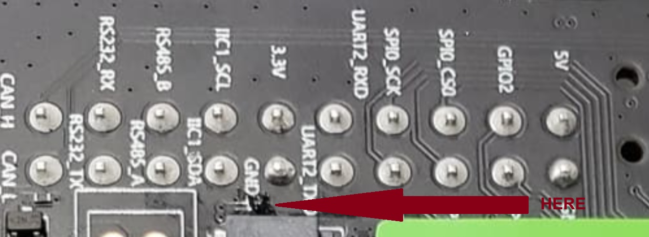
As for the port numbers they seemed off to me as well and through some trail and error I was able to find what I believe to be the correct pin. When looking at the pdf for W8 connector it says that the port is PH.06 but when looking at nvidia’s dsti (excel sheet see image attached or https://developer.nvidia.com/downloads/jetson-orin-nx-and-orin-nano-series-pinmux-config-template) you get pin 18 corresponding to pin# 124 is on port PP.06. When trying to run PH.06 I got no feedback from pin as input and no output change. PP.06 has correct input behavior but no change on output. I think that that is a typo in documentation. 
TY Roman 
Hi there, Idunno I would try to find out for sure the pins and ports involved. run some test sketches toggling thru the output ports to be sure. Input wise maybe the logic is inverted like Xiao ,input pullup a good link is here → https://roboticsbackend.com/arduino-input_pullup-pinmode/
also not sure if it’s relevant but check the firmware and update if need be.
HTH
GL PJ
I have confirmed that I am on the correct pins, and that the logic is not reversed. I have also tried with the pull up and down resistors and still no luck. I have tested a few other pins (non-gpio) and they work as intended. It is just the GPIO pin that is not working, which is weird. I have access to a Nvidia Orin AGX and the GPIO pins on that work correctly when doing the same as I have done on the Nvidia Orin NX. I won’t have access to the AGX for much longer and will need to use the NX and cannot seem to figure out why it is not outputting as intended.
 Roman
Roman
WoW Roman,
I would say you have done the proper checking, Time to send Seeed an Email, YMMV
My only last shot would be any Firmware involved, is a roll-back possible? Wouldn’t be the first time and update put out hastily wrecks other stable functions. So look there too.
You have a picture of the setup?
HTH
GL PJ
A roll back is not possible as far as I know. This setup is the first time the board was setup, I will upload a picture of the setup when I get back into the office on Monday. I will be traveling this weekend. I will also reach out to Seeed Monday. Thank you for your responses, they have been helpful!
Roman
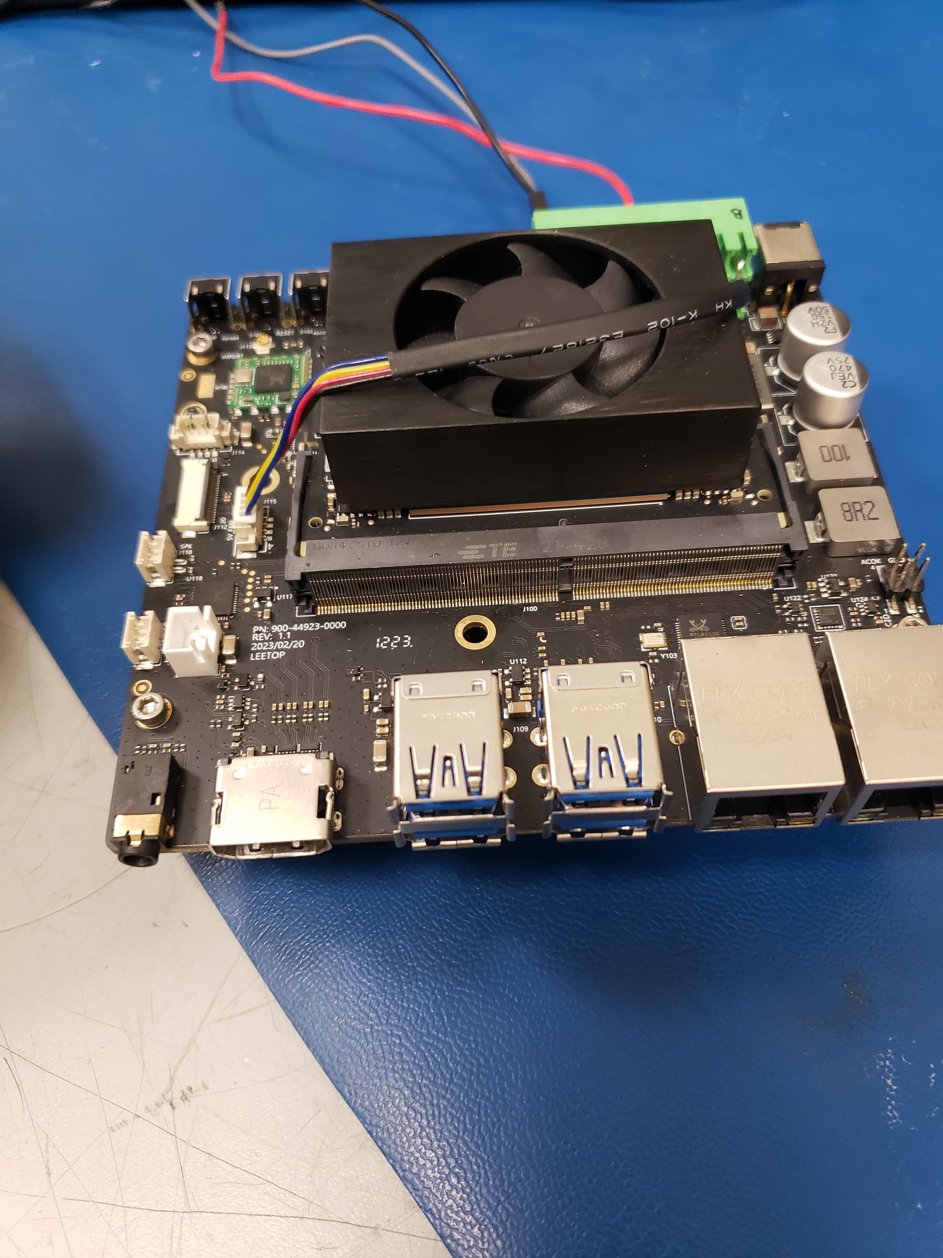
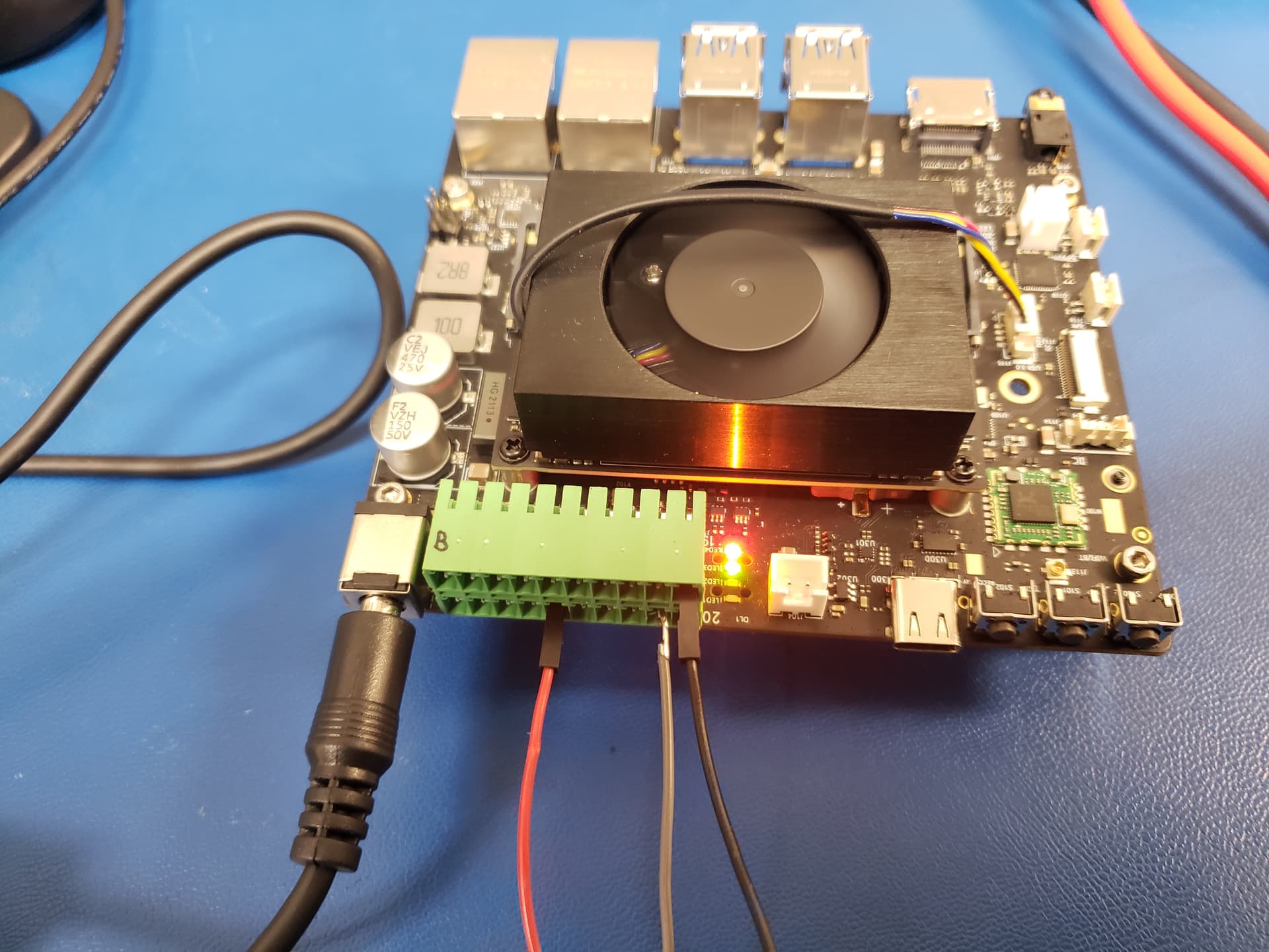
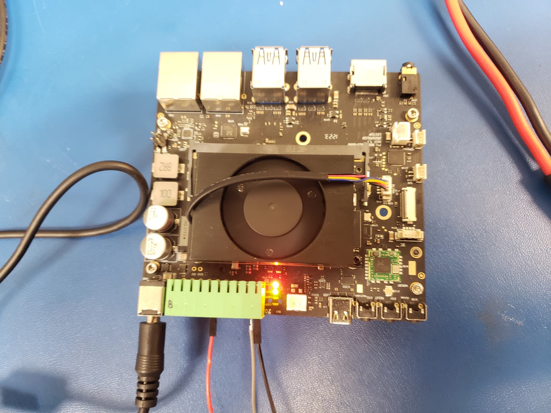
This is pics of the board I have been using. The black wire is ground, red is 3.3V power, and grey is the GPIO I want to control that has not bee outputting voltage but has been able to read it. I am emailing Seeed Studio directly to try to resolve my issue. I will post the solution to my problem in case someone runs into anything similar.
Thanks all,
-Roman 
Hi there,
Can you try to switch the GND’s to the other one , just for grins, and what is in the picture is it just dirt?
HTH
GL
PJ
That was just dirt. I have wiped it away. Its all clean now  . I have tried the other ground and the same result each time. I have tested it on both A607 boards I have and they are both behaving in the same manner. I have also reimaged one of my boards today with a fresh build…and alas nothing has changed
  .
.
Roman
OK I’m looking at an A205E board that’s the part number on the bottom of your picture.
PN: 900-44923-0000
I’m looking at this PDF also.
https://files.seeedstudio.com/products/102110774_A205E%20carrier%20board/A205E%20carrier%20board%20Datasheet.pdf
Wacky?
just throwing it out there.
GL
I agree that it should be working…also I forgot to attach it earlier but here is the pdf of the board I am using: https://files.seeedstudio.com/products/NVIDIA/A607-Carrier-Board-for-Jetsson-Orin-NX-Nano-Datasheet.pdf
Thx
Hello,
Perhaps you can try the following two methods to see if they can solve your problem:
Method 1: Execute this command:
busybox devmem 0x02430030 32 0x00000000
Please note that this is only a temporary solution.
Method 2: Change the pinmux, you will need to flash the device. Here are the steps to flash:
nvidia,io-high-voltage = <TEGRA_PIN_DISABLE>.
sudo ./flash.sh --no-systemimg -c bootloader/t186ref/cfg/flash_t234_qspi.xml jetson-orin-nano-devkit mmcblk0p1.
I hope it will be helpful.
Hello,
1st thing I tried is Method 1. It caused the pin to work in what I think is a “floating” state. It was able to output current but it does not go to the correct levels. I only have my multi-meter hooked up (no load).
I run (inside the /sys/class/gpio/PP.06 as su):
“$busybox devmem 0x02430030 32 0x00000000”
“$echo out > direction”
“$echo 0 > value” voltage value is 0V as expected
“$echo 1 > value” voltage value becomes 1.7V instead of 3.3V value goes to 3.3V after removing and reattaching positive lead of multimeter
“echo 0 > value” voltage value becomes 1.4V from 3.3V instead of 0V, similarly when I remove the positive lead of my multimeter and reattach it, it goes to 0V
I have seen this issue before when the pin can only handle a tiny amount of current. I am curious how much current is pin 18 on the W8 20pin header rated for? I have not been able to find this information. Ideally I would like to have the pin capable of handling at least 1mA.
I am currently working on Method 2 and will update as I progress.
Thank you for your help so far (things are starting to progress again)!
–Roman
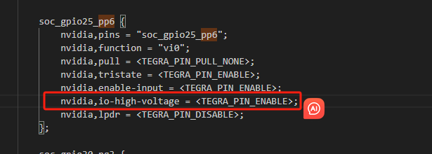
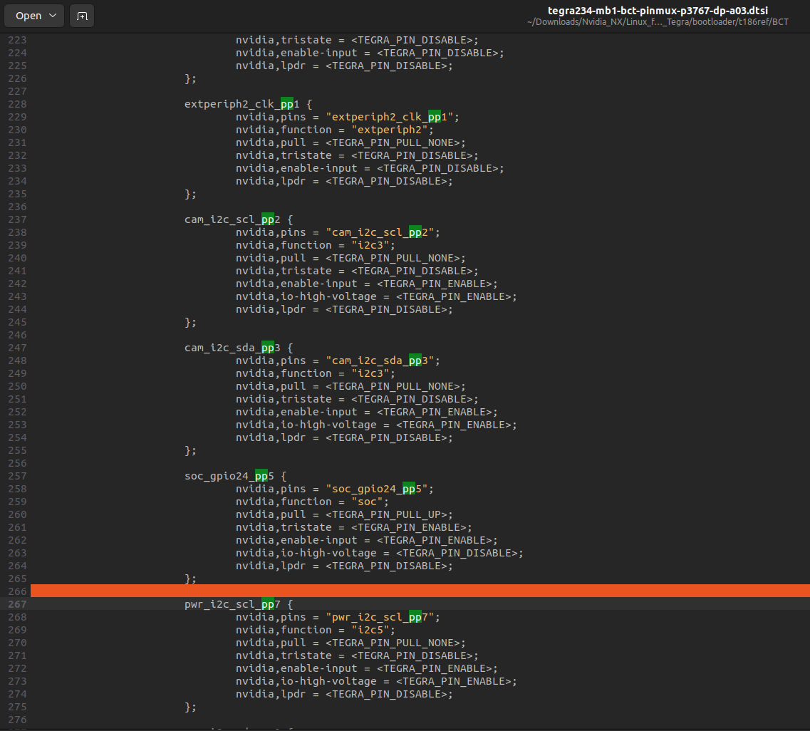
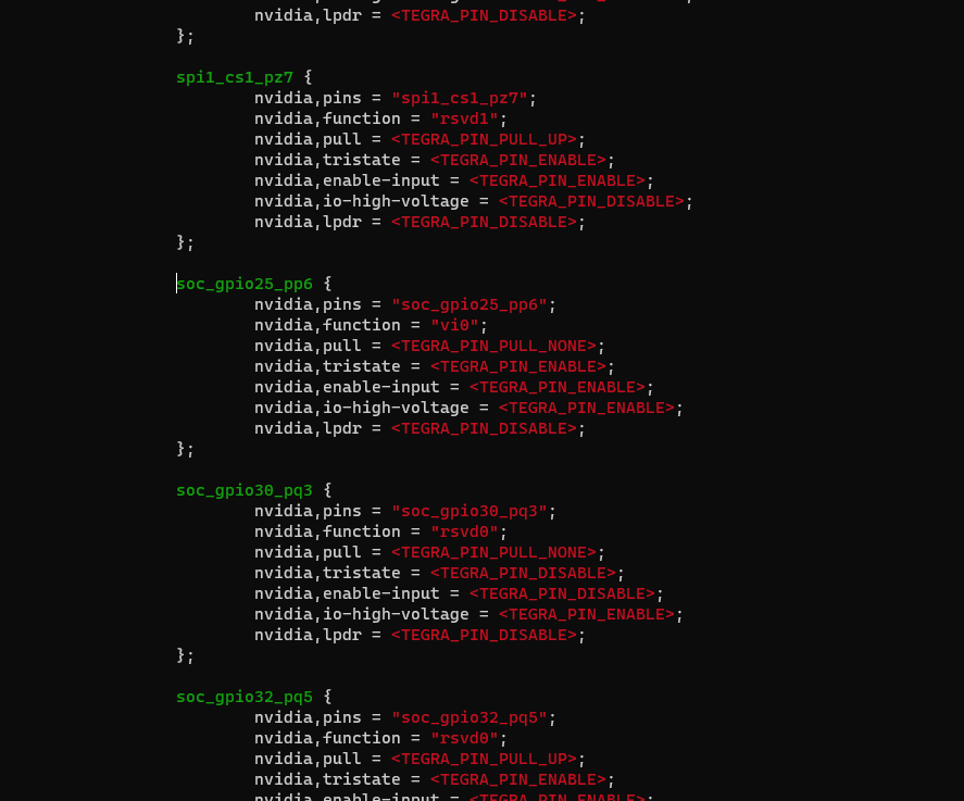
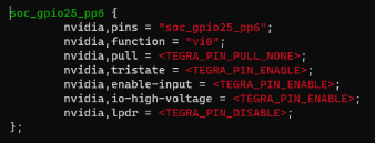
When trying to locate that directory and soc_gpio25_pp6 I cannot find it. In my bootloader\t186ref\BCT\tegra234-mb1-bct-pinmux-p3767-dp-a03.dtsi I have3 the following:
I originally flashed following A607 Carrier Board | Seeed Studio Wiki
If I use PP.05 instead of PP.06 with Method 1 I get the same results as with PP.06. That is pin 18 of the W8 20 pin header behaves the same whether I change the value in /sys/class/gpio/PP.06 or /sys/class/gpio/PP.05. Is this expected? I feel like this should not be the case.
To continue Method 2 do I add the soc_gpio25_pp6{…}; to my bootloader\t186ref\BCT\tegra234-mb1-bct-pinmux-p3767-dp-a03.dtsi? Or do I simply change the values of my version soc_gpio24_pp5{…};?
–Roman
I was able to find soc_gpio25_pp6. It seems like I overlooked it yesterday in my haste, my apologies.
Also, thank you for the information on the pin’s current limit.
I will continue to try Method 2 and keep you updated.
Thanks,
–Roman
I looked at my bootloader\t186ref\BCT\tegra234-mb1-bct-pinmux-p3767-dp-a03.dtsi file and set my values to match
exactly. I have flashed and it behaves the same until I reapply Method 1. That is the pin does not drive any voltage until I run “busybox devmem 0x02430030 32 0x00000000” then it enters the weird “floating” state.
Side Note: I believe the “floating” state is from the pin only being able to output 60 μA. Also is there some example of someone using this pin to drive an LED somewhere? If so can I get an electrical diagram of that or some example with this pin driving something?
Sorry, we do not have an example circuit diagram for this