Hi there,
AND Welcome Here…
So, To answer your questions:
-
What are the half-circle holes? Those are called castellated holes (or castellated mounting pads). They are standard plated through-holes that get cut in half during PCB panel milling, leaving exposed, plated copper edges on the sides and bottom.
-
Why have both? Flexibility.
-
The full round holes are standard 2.54 mm (0.1") pitch through-holes for standard pin headers or socket strips—perfect for breadboarding and prototyping.
-
The castellated edges let the XIAO be used like a surface-mount module (SMD). You can lay the XIAO flat directly onto a custom PCB carrier without any through-hole pins sticking through the bottom, soldering the edges directly down like a stamp. This keeps vertical clearance practically flush.
-
-
The unexpected advantage: Beyond surface mounting, those castellated notches give you positive mechanical alignment. In fact, I designed a 3D-printed socket here on the forum that takes advantage of the XIAO’s exterior dimensions and those castellations to pressure-fit / snap the board firmly into place without needing permanent solder or extra fasteners. It makes swapping modules quick and holds everything secure.
-
Pin spacing & boards: Yes, the spacing between the two 7-pin rows is 0.6 inches (15.24 mm), making it a standard DIP-14 width. It fits standard breadboards (spanning the center groove) and any standard 0.6" wide proto-board layout. Seeed also makes the Seeed Studio Expansion Board for XIAO (and several third-party breakout boards) that already include pre-soldered female sockets, Grove connectors, and power circuitry out of the box.
HTH
GL  PJ

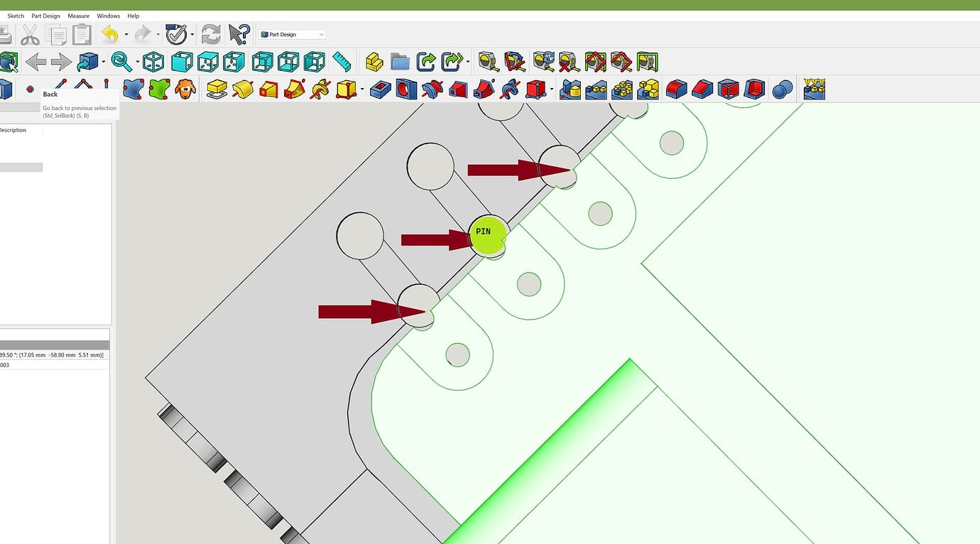
I used the geometry to bite into the pins.


https://forum.seeedstudio.com/t/another-xiao-socket-adapter-revision-iii/266872?u=pj_glasso