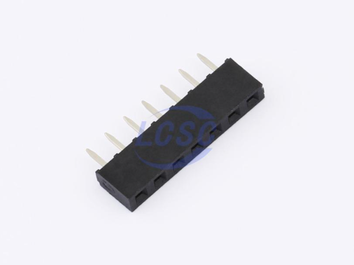
It looks like I’m going to have to make a custom board to finish my project, but I’m having great difficulty tracking down the correct female headers. The Grove shield has 2 x 7 socket, 4mm high female headers so I presume Seeed must be sourcing them from somewhere. Where that “somewhere” is is proving impossible to find. Does anyone know the manufacturer and part numbers for these?
I can find 8mm high sockets and 1.27mm high sockets but both of these cause other problems with finding pogo pins of the correct lengths and in fitting the board into the case. On the Grove shield, the base of the Xiao board sits 8mm above the shield PCB and I want to replicate that spacing.
P.S, I am lousy at soldering so I plan to have the boards built for me. I would struggle badly to solder in my own headers.
I tend to stick with the standard height 2.54mm Pin Header (Female). I found the shorter connectors to be unreliable, especially those on the XIAO Expansion Board (with Pogo Pins).
If you want good quality use round pins and receptacles, preferably gold plated.
Re sources. It depends where you’re planning to have the board/s assembled.
Re assembly. As you’re having the board/s assembled, and want to use the underside pads on the XIAO, I’d recommend going “surface mount”. Pogo’s are really useful for testing, not sure on long term use.
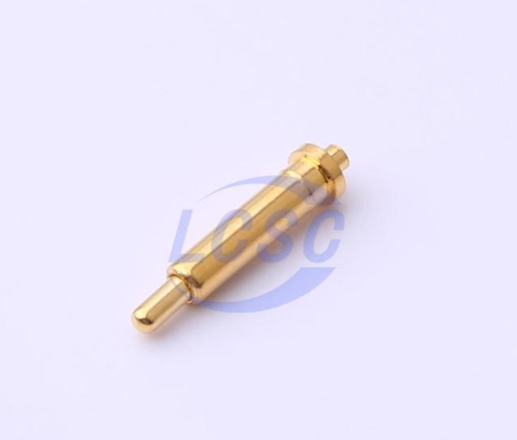
Thanks for the response, The board I need is incredibly simple. It just consists of a Grove connector, a battery connector, a socket for a Xiao nRF54LM20A and two pogo pings to reach the Xiao’s power pads. I only need it because, as I finally discovered, the Grove shield that I was using and the nRF54 aren’t compatible when it comes to power management: the shield’s power management is flaky, and the nRF54’s built in chip needs power fed directly to the pads. I think surface mounting would be overkill, plus it wouldn’t reuse the existing components that I have. This is a hobby project, so pogo pins will be absolutely fine.
You can see several PCB I had made on here in some other threads, For the Battery Soldering IS the most reliable, The Socket works well and is still working on the prototype I made that uses it, biggest issue is “Moving” the Pads’ Seeed
HTH
GL PJ
You can see how the sockets are made, and Add pins where you need. there is a video of it on here.
Nice! Unfortunately I don’t have a 3D printer. (This is the subject of ongoing domestic negotiations.) In fact, I don’t even have a workbench, just a desk. My plan was to build my project Lego-style as much as possible so as to avoid the need to solder. I think I may have to bite the bullet and use taller sockets with longer pogos. This will mean sacrificing the case that cost me a small fortune because, again, I don’t have a 3D printer.
PS> The trick that worked for me re the 3D printer was showing and then printing the wife things she could use, eg phone holder for desk and car, plant trellises, kitchen “helpers”, drawer organisers
Well, Ok. @grobasoz has you covered on the hardware angle and partial on the other.
I admit it, I salted the deck at my house, I was playing a lot of youtube 3D printing video’s back when the 3D printers really started to come to makers, one at home was “WHAT” ? WHY ?
Somehow, an Ender 3Pro showed up for my Bday one year, and the FitBit holder (hers)I printed, I already know how far it is, and then the “SPICE Rack” brackets and HF mag-strip, printed next, HERE"S the VIDEO btw.. for the dates, 5-6 years at least ? sealed the deal. Yea 5 printers later…I see color so.
Keep trying ,eHmm’ a.k.a.(negotiating)
Small Plasma cutter table coming up same way. for metal parts though…
One thing worth checking is the required mating height, not just the 7-pin count and pitch. On the XIAO, the available clearance can make otherwise compatible headers unsuitable. You have to compare the header height against the board, any attached expansion board, and the intended mating connector before ordering. Has anyone found a specific part that fits the XIAO while maintaining the required clearance?
Yes, and discovered the hard way. My pogo pins came up 0.5mm too short. My bodged but working solution is a blob of solder on each of the battery pads on the bottom of the chip.
(There’s a l-o-n-g and continuing story about my attempts to make my first PCB. I will write up at a later date.)
That 0.5 mm difference can make a surprisingly big difference with pogo pins. The solder blobs are a clever workaround, especially for getting the prototype working.
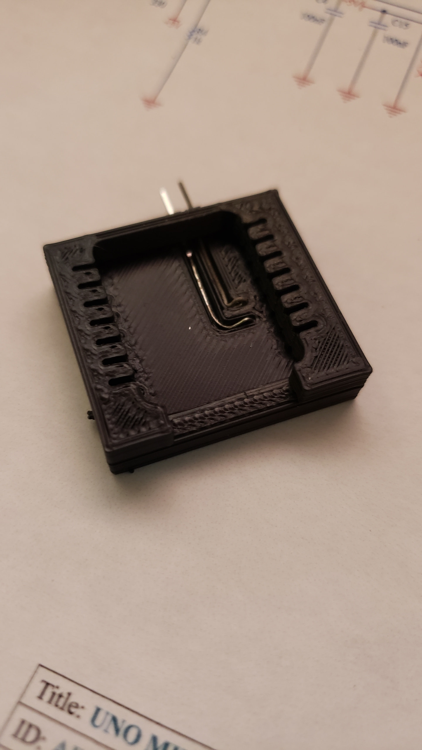
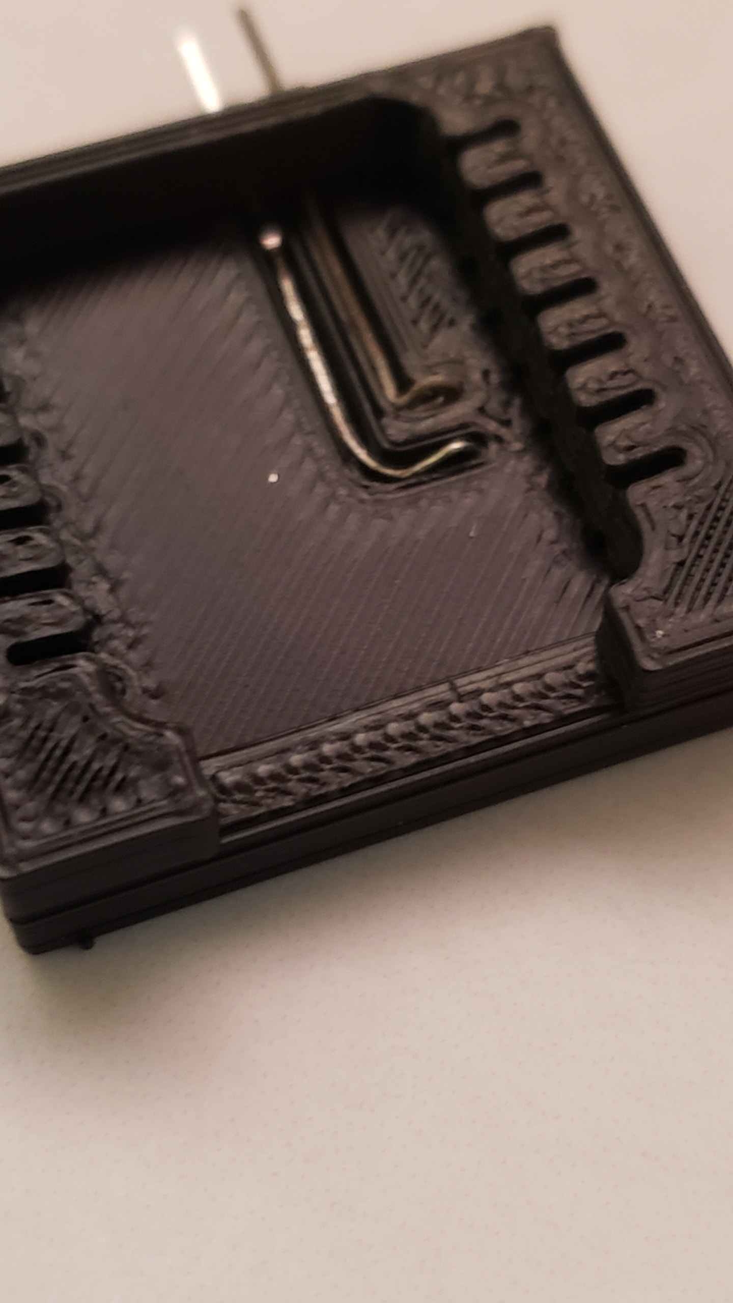
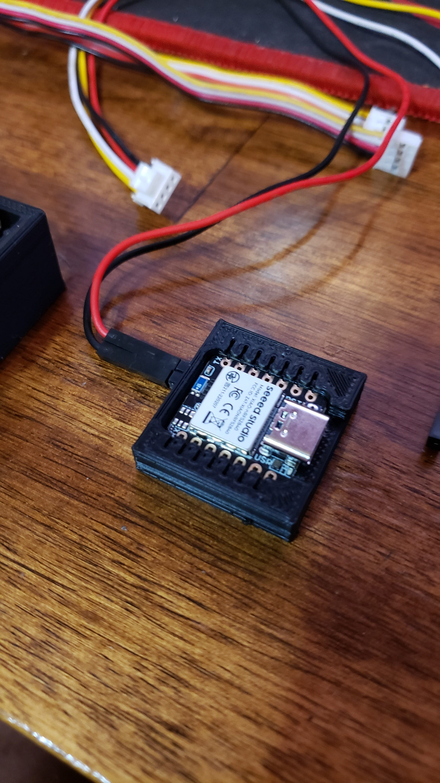
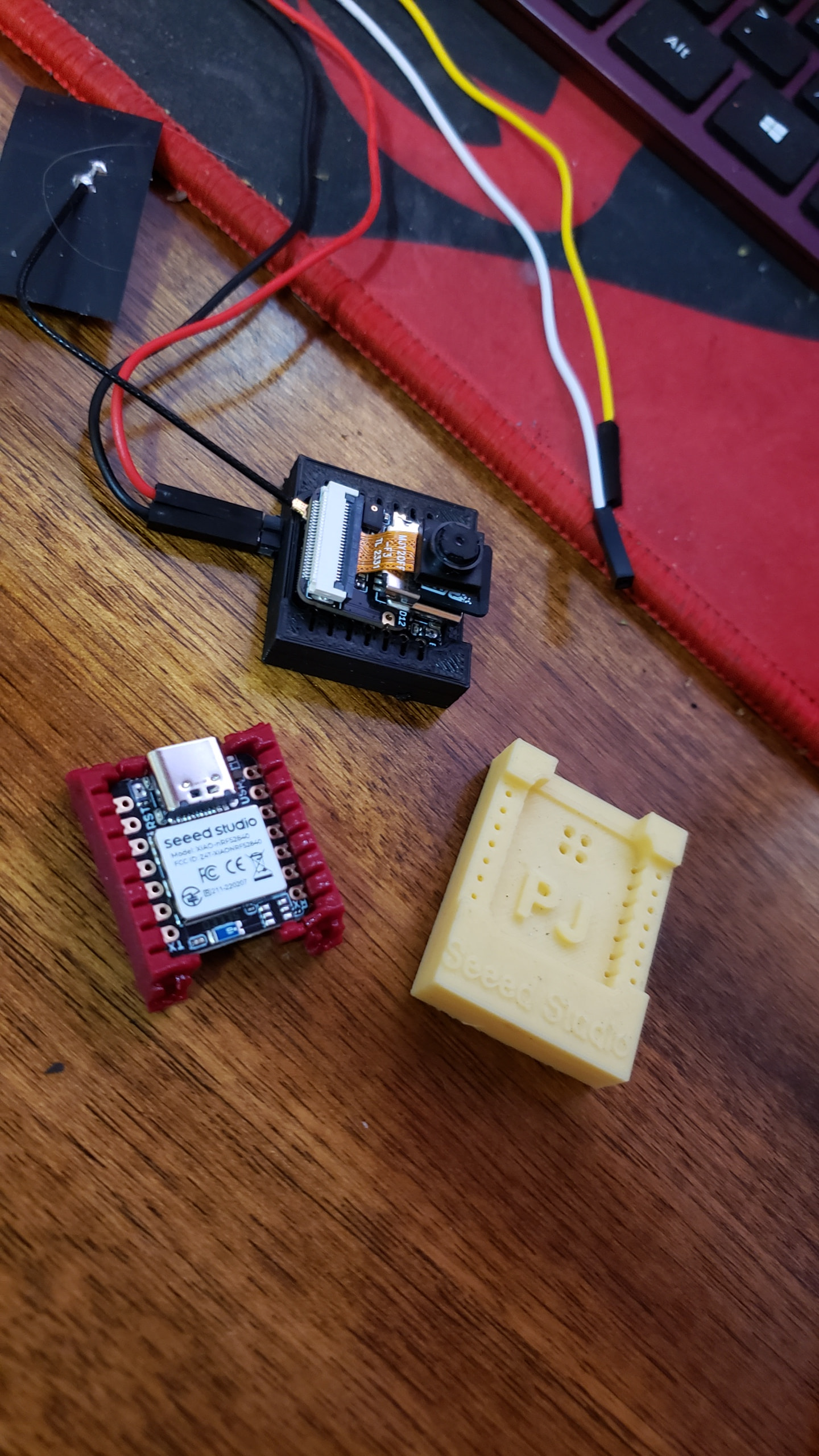


 PJ
PJ 



 Yea 5 printers later…I see color so.