I would study Gary’s example code. It gives you a lot of control over several pins. However, I can’t think of a way immediately that would wake-up with one pin going HIGH or another going LOW.
Hi there,
And Welcome here… after a few posts you can post code and pics and other stuff so reply if you can. First Start with the Basics, NO Kitchen Sink approaches here.
Do you have a wakeup working on GPIO4 going low? that’s the lowest hanging fruit (easiest) first.
Start there.
Note : it’s wise to Post up a Picture of how it’s connected if it’s more than just a button on the pin 3 or D2 logically. KNOW this… sometimes the libraries or BSP file used to compile the code with(BSP=pins for what MCU, etc & MACROS) wants the pins as GPIO nomenclature others and some of the LIB’s have PIN macros , so the Logical pin names will work.
If you get stuck, always try that switch up.
Post up the code you have tried, use the code tags above “</>” paste it in there. ![]()
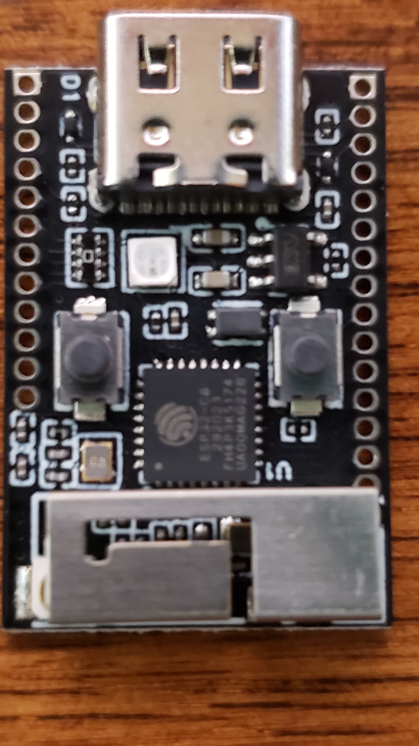
Be aware, The C3 is Different than the REST of the esp32 family. in the SPI, UARTS, and GPIO’s especially. You can see from previous posts, that assumptions on how it works will lead you the wrong way ![]() and waste your time. If your using a dev kit (a true one like pictured) don’t expect everything to translate to a Xiao’s or AFruit, or SparksRfun or Robot guy’s Hardware offering’s FYI
and waste your time. If your using a dev kit (a true one like pictured) don’t expect everything to translate to a Xiao’s or AFruit, or SparksRfun or Robot guy’s Hardware offering’s FYI ![]()
a real C3 is pictured.
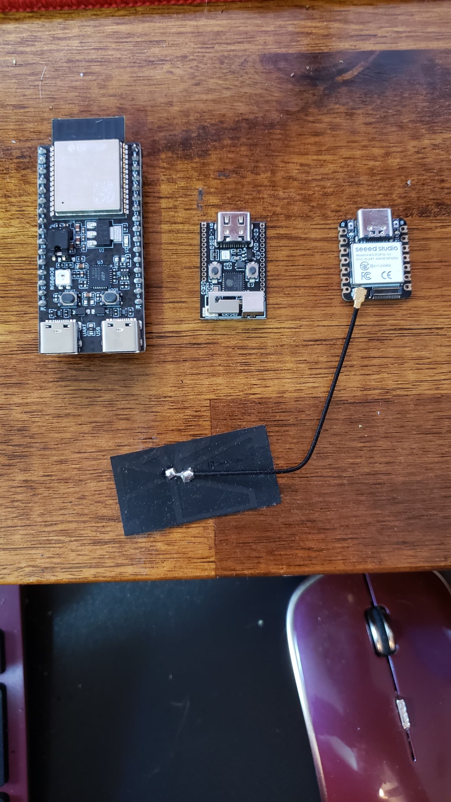
Some choices…

A real C6 dev board… BTW
Random C6 offering. (older antenna)
HTH
GL ![]() PJ
PJ ![]()
IMO, there certainly IS a software way to approach it, but walk before you run. (spoiler alert) checking the Serial port connected is a way to tell if it’s USB is plugged in too!, Keep in mind the C3 can get esp_sleep_get_wakeup_cause() in code too! not Ideal in every case this method detects if the device was woken up by USB power after a deep sleep. While not a direct detection, it’s useful for some power management applications.
Hi there,
So Leg up ![]() Here is one I used in December , tested now works good you can start with that! if you don’t have anything yet.
Here is one I used in December , tested now works good you can start with that! if you don’t have anything yet.
There’s probably a video of it in action too!
code as tested…
// Xiao ESP32C3 Sleep and Wake Up demo...
// Blinks LED on PIN D10 - 10 times then Sleeps , Outputs Blink and sleep on Serial port too!
// Keeps track of the Boot count. (I use this to do different sub functions)
// BSP 3.0.1 was used .
// Pressing button connected to D1 wakes Up the MCU
// The Wake up reason is Also printed.
// Tested AOK , by PJG 3/23/24 and 12/30/23


#define LED 10  // or use LED_BUILTIN for on-board LED
#define INTERRUPT_PIN 2 // I used a push button connected to Vcc and Pin 1
RTC_DATA_ATTR int bootCount = 0;

void setup() {
  Serial.begin(115200);
  delay(1000);
 Serial.println("Xiao C3 Sleep/Wake Demo - Power ON - " __DATE__ " at " __TIME__);
  pinMode(LED, OUTPUT);
  digitalWrite(LED, LOW);

  ++bootCount;
  Serial.println("Boot number: " + String(bootCount));

  print_wakeup_reason();

  Serial.println("Going to blink the LED 10 times");
  blink(10);  // Allow time for wakeup
  Serial.println("Going to sleep now");
  delay (250);
 // esp_sleep_enable_bt_wakeup(void)
  esp_deep_sleep_enable_gpio_wakeup(1 << INTERRUPT_PIN, ESP_GPIO_WAKEUP_GPIO_HIGH);
    delay (250);
  esp_deep_sleep_start();

  Serial.println("This will never be printed");
}

void loop() { }

void blink(int times) {
  for (int i = 0; i < times; i++) {
    digitalWrite(LED, HIGH);
    delay(1000);

    digitalWrite(LED, LOW);
    delay(1000);
    Serial.print("Blink ");
    Serial.println(i + 1);
  }
}

void print_wakeup_reason() {
  esp_sleep_wakeup_cause_t wakeup_reason;

  wakeup_reason = esp_sleep_get_wakeup_cause();

  switch (wakeup_reason) {
    case ESP_SLEEP_WAKEUP_EXT0:
      Serial.println("Wakeup caused by external signal using RTC_IO");
      break;
    case ESP_SLEEP_WAKEUP_EXT1:
      Serial.println("Wakeup caused by external signal using RTC_CNTL");
      break;
    case ESP_SLEEP_WAKEUP_TIMER:
      Serial.println("Wakeup caused by timer");
      break;
    case ESP_SLEEP_WAKEUP_TOUCHPAD:
      Serial.println("Wakeup caused by touchpad");
      break;
    case ESP_SLEEP_WAKEUP_ULP:
      Serial.println("Wakeup caused by ULP program");
      break;
    default:
      Serial.printf("Wakeup was not caused by deep sleep: %d\n", wakeup_reason);
      break;
  }
}
Serial output ;
Xiao C3 Sleep/Wake Demo - Power ON - Mar 23 2025 at 14:10:16
Boot number: 1
Wakeup was not caused by deep sleep: 0
Going to blink the LED 10 times
Blink 1
Blink 2
Blink 3
Blink 4
Blink 5
Blink 6
Blink 7
Blink 8
Blink 9
Blink 10
Going to sleep now
Xiao C3 Sleep/Wake Demo - Power ON - Mar 23 2025 at 14:10:16
Boot number: 2
Wakeup was not caused by deep sleep: 7
Going to blink the LED 10 times
Blink 1
Blink 2
Blink 3
Blink 4
Blink 5
Blink 6
Blink 7
Blink 8
Blink 9
Blink 10
Going to sleep now
Xiao C3 Sleep/Wake Demo - Power ON - Mar 23 2025 at 14:10:16
Boot number: 3
Wakeup was not caused by deep sleep: 7
Going to blink the LED 10 times
Blink 1
Blink 2
Blink 3
Blink 4
Blink 5
Blink 6
Blink 7
Blink 8
Blink 9
Blink 10
Going to sleep now
HTH
GL ![]() PJ
PJ ![]()
@aaronhughelectron - Just call the ext wake twice, once for each level.
Each of the 5 wake sources can be set to wake on one of 5 settings…
0: disable wakeup by RTC GPIO
1: wake up the chip upon the rising edge
2: wake up the chip upon the failing edge
3: wake up the chip upon the rising edge or the failing edge
4: wake up the chip upon low level
5: wake up the chip upon high level
But only Low and High are supported (Arduino).
  if (esp_deep_sleep_enable_gpio_wakeup(WAKE_PIN_LOW_MASK, ESP_GPIO_WAKEUP_GPIO_LOW) == ESP_OK) {
    Serial.println("Wake Low Enabled, Mask = " + String(WAKE_PIN_LOW_MASK));
  } else {
    Serial.println("Wake Low Error");
    noSleep = true;
  }

  if (esp_deep_sleep_enable_gpio_wakeup(WAKE_PIN_HIGH_MASK, ESP_GPIO_WAKEUP_GPIO_HIGH) == ESP_OK) {
    Serial.println("Wake High Enabled, Mask = " + String(WAKE_PIN_HIGH_MASK));
  } else {
    Serial.println("Wake High Error");
    noSleep = true;
  }
Edit> Mask set accordingly… for example…
#define WAKE_PIN_0 GPIO_NUM_2  // D0
#define WAKE_PIN_1 GPIO_NUM_3  // D1
#define WAKE_PIN_2 GPIO_NUM_5  // D3

#define WAKE_PIN_LOW_MASK ((1 << WAKE_PIN_0) + (1 << WAKE_PIN_2))
#define WAKE_PIN_HIGH_MASK (1 << WAKE_PIN_1)
Hi there,
Have you tried this suggestion /Code on a XIAO C3 ?
I’m betting NO!
GL ![]() PJ
PJ ![]()
Hi there,
Yep , that’s a C3 ![]() Good Job… LOL
Good Job… LOL ![]()
![]()
this is the GOLD.
" if (esp_deep_sleep_enable_gpio_wakeup(WAKE_PIN_LOW_MASK, ESP_GPIO_WAKEUP_GPIO_LOW) == ESP_OK) {"
GL ![]() PJ
PJ ![]()
Which BSP did you use , If I may ask?
Hi @PJ_Glasso, a big thank you for all the information! I need some time to go through it first. For your last question, I am using Arduino IDE with ESP32 package on a MacbookPro. (Good morning from the UK!)
1 Like
And for the previous discussion on ESP32 variants, I have some other background information for the project I have been working that you might find useful also FYI…
This circuit I am testing is later to be used on designing a PCB that will be installed on a personal physical device. That being said, I am afraid there is a constraint to both the size and cost for the MCU dev board. If it is too big, like in some of your pictures, it wouldn’t be able to fit in the device (it is such a pity as they are well-known to be great dev boards)! ![]() XIAO ESP32C3 board is thought to be the best option so far balancing size and functionality (battery charging, BLE/WiFi, etc.).
XIAO ESP32C3 board is thought to be the best option so far balancing size and functionality (battery charging, BLE/WiFi, etc.).
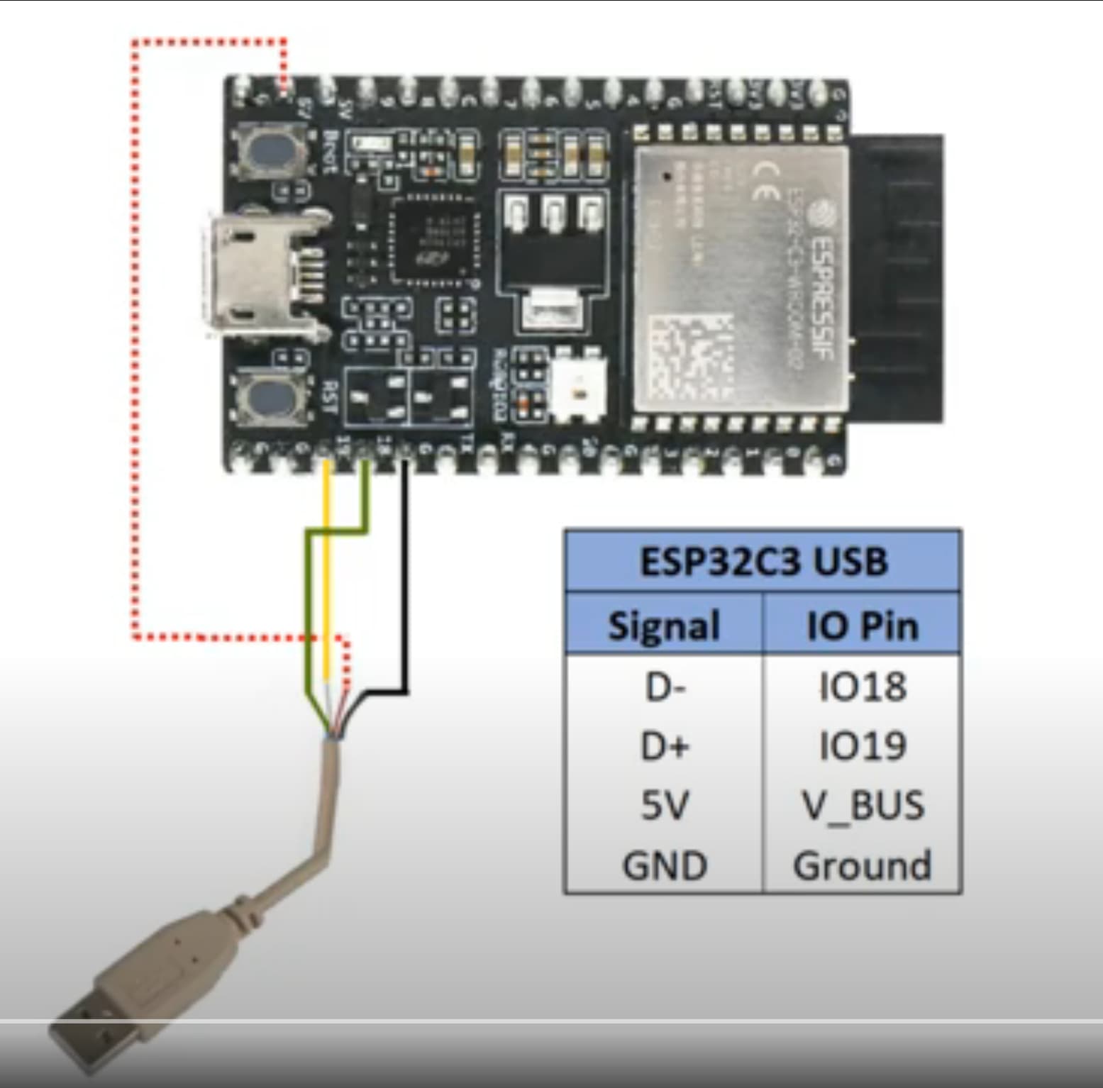
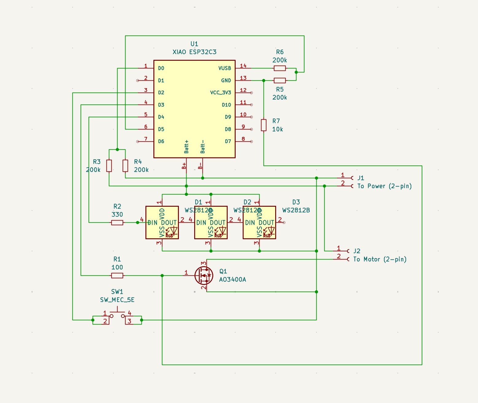
So the plan is to eventually make a PCB where I install all the components including XIAO ESP32C3 board on it. Would you say this is how I should go about for the PCB?
Below is the schematic of my full circuit (so far):
NOW I HAVE TRIED IT, THIS IS REALLY GOOD THANK YOU SO MUCH!! ![]()
And thank you for your advice on:
If your using a dev kit (a true one like pictured) don’t expect everything to translate to a Xiao’s or AFruit, or SparksRfun or Robot guy’s Hardware offering’s FYI
Turns out that I can put more than one esp_deep_sleep_enable_gpio_wakeup() in my code with the correct calling order (like how you did in your example), like LOW first then HIGH. But it saves so much of my time and avoided extra components like diodes and no need to do OR circuit anymore yay!! Thanks PJ!
1 Like
Hey, thanks for sharing your experience!
Yeah, dealing with external deep sleep on the Xiao ESP32C3 can be tricky, especially with GPIO wakeup sources. That bitmask part (1ULL << 3) is a crucial detail that’s easy to overlook! A lot of people try using the GPIO number directly instead of the proper bitmask, which leads to frustrating issues.
Your approach makes perfect sense, and the delays for easier debugging are a smart move—definitely saves some headaches when making changes.
Appreciate you dropping your code snippet here! Hope it helps others struggling with the same issue.
Hi there,
Sure thing, we are ALL here to help SO I’m glad it was useful. It’s funny Sleep would be the big topic these days, NOT Mega_GIGA-Watts-Hz. /per ferKin speed. Turns out, He Who SLeeps bests Lasts Longest! ![]()
Interrupt and waking are almost an Art form, ![]()
HTH
GL ![]() PJ
PJ ![]()
@grobasoz I think I require your help again. Your code works great with the C3 but when I port it to the S3 no luck. Very frustrating. I thought I fully understood your code and it would require a few simple changes for it to work with the S3. This has not been the case. The S3 goes into deep sleep but then immediately wakes up. It repeats this cycle.
The reason I want to use the S3 is for production reasons. The S3 allows the board to be directly connected/soldered to the back of the keypad (see picture) significantly reducing time to fabricate.
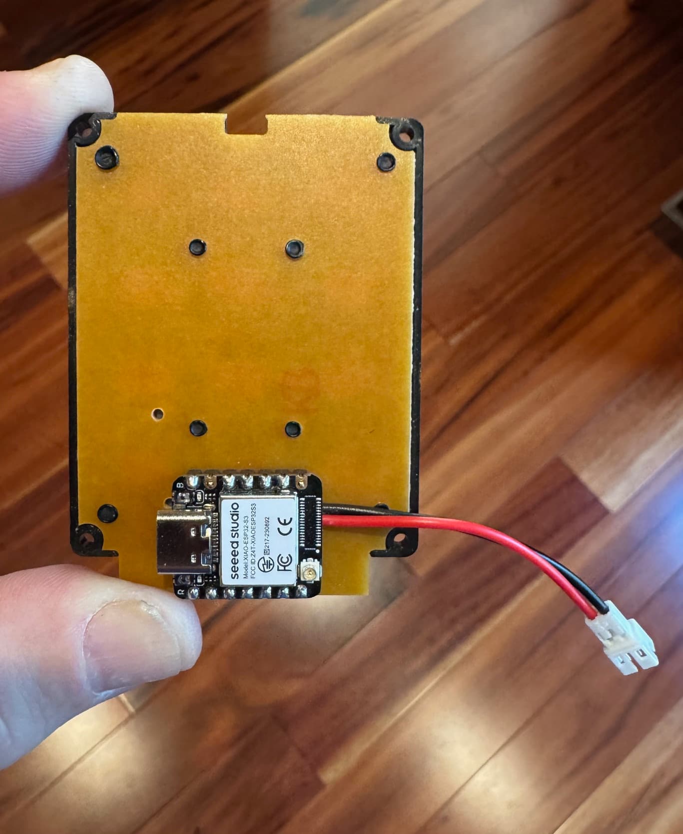
However, in order for this to work with the keypad I have to change the pin mappings which in turn means I need to use the row pins to wake-up the S3 since the D6 pin (GPIO 43) on the S3 is not an RTC pin (all others on that side of the XIAO ESP32S3 are).
Here is the code (I have tried lots of variations, but this version most closely matches your original code):
/***********************************************************************************************
Any Key Wake-up Test Code
v1.0
date: 08-Apr-2025
hardware: XIAO_ESP32S3
          3x4 Matrix Keypad

This code is based on code developed by Gary Robas to have the XIAO_ESP32S3 wake-up when any
key is pressed.
************************************************************************************************/
#include <Keypad.h>

#define USE_DEEP_SLEEP
#define SLEEP_TIMEOUT  6000  // 10mS intervals

// Define pin mapping - must use RTC pins for rows
#define COL_PIN_1 GPIO_NUM_5   // D4 - P3
#define COL_PIN_2 GPIO_NUM_43  // D6 - P1
#define COL_PIN_3 GPIO_NUM_3   // D2 - P5

#define ROW_PIN_1 GPIO_NUM_6   // D5 - P2
#define ROW_PIN_2 GPIO_NUM_1   // D0 - P7
#define ROW_PIN_3 GPIO_NUM_2   // D1 - P6
#define ROW_PIN_4 GPIO_NUM_4   // D3 - P4

#define ROW_PIN_MASK ((1 << ROW_PIN_1) + (1 << ROW_PIN_2) + (1 << ROW_PIN_3) + (1 << ROW_PIN_4))

const byte ROWS = 4;  // Rows
const byte COLS = 3;  // Columns

// Define the symbols on the buttons of the keypads
char keys[ROWS][COLS] = {
  { '1', '2', '3' },
  { '4', '5', '6' },
  { '7', '8', '9' },
  { '*', '0', '#' }
};

byte colPins[COLS] = { COL_PIN_1, COL_PIN_2, COL_PIN_3 };             // Connect to the column pinouts of the keypad
byte rowPins[ROWS] = { ROW_PIN_1, ROW_PIN_2, ROW_PIN_3, ROW_PIN_4 };  // Connect to the row pinouts of the keypad

// Initialize an instance of class NewKeypad
Keypad keypad = Keypad( makeKeymap(keys), rowPins, colPins, ROWS, COLS);

static uint16_t sleep_count = 0;  // Sleep after x seconds

#ifdef USE_DEEP_SLEEP
static bool sleep_permitted = true;  // False if error with sleep setup

// Prepare GPIOs for wake
void prep_for_wake(void) {
  // Allow rows to be pulled low when in deep sleep
  digitalWrite(COL_PIN_1, HIGH);
  digitalWrite(COL_PIN_2, HIGH);
  digitalWrite(COL_PIN_3, HIGH);

  // Release outputs held during deep sleep
  gpio_hold_dis(COL_PIN_1);
  gpio_hold_dis(COL_PIN_2);
  gpio_hold_dis(COL_PIN_3);
}

// Prepare GPIOs for sleep
void prep_for_sleep(void) {
  pinMode(ROW_PIN_1, INPUT);
  pinMode(ROW_PIN_2, INPUT);
  pinMode(ROW_PIN_3, INPUT);
  pinMode(ROW_PIN_4, INPUT);

  // Sleep - Cols are outputs
  pinMode(COL_PIN_1, OUTPUT);
  pinMode(COL_PIN_2, OUTPUT);
  pinMode(COL_PIN_3, OUTPUT);

  // Allow rows to be pulled low when in deep sleep
  digitalWrite(COL_PIN_1, LOW);
  digitalWrite(COL_PIN_2, LOW);
  digitalWrite(COL_PIN_3, LOW);

  // Maintain outputs during deep sleep
  gpio_hold_en(COL_PIN_1);
  gpio_hold_en(COL_PIN_2);
  gpio_hold_en(COL_PIN_3);

  if (esp_sleep_enable_ext1_wakeup_io(ROW_PIN_MASK, ESP_EXT1_WAKEUP_ANY_LOW) == ESP_OK) {
    Serial.println("Keypad Wake Mask : 0x" + String(ROW_PIN_MASK, HEX));
  } else {
    Serial.println("Keypad Wake Error");
    sleep_permitted = false;
  }

  Serial.println("Deep Sleep!");
}

void do_deep_sleep() {
  prep_for_sleep();
  Serial.println("Going to sleep now");
  Serial.flush();
  delay(100);
  gpio_deep_sleep_hold_en();
  esp_deep_sleep_start();
}
#endif  // USE_DEEP_SLEEP

void setup() {
  Serial.begin(115200);

#ifdef USE_DEEP_SLEEP
  // Before starting the keypad, release held rows.
  prep_for_wake();
#endif //USE_DEEP_SLEEP

  Serial.println("Starting!");
}

void loop() {
  char key = keypad.getKey();

  if (key) {
    Serial.print("Key pressed: ");
    Serial.println(key);
  }

  if (sleep_count++ > SLEEP_TIMEOUT) {
#ifdef USE_DEEP_SLEEP
    if (sleep_permitted) {
      do_deep_sleep();
    }
#endif
    Serial.println("Sleep!");
    delay(5000);  // Testing
    sleep_count = 0;
  }

  delay(10);
}
Hi there,
SO , I find this ![]()
SLEEP_TIMEOUT = 6000
The comment says “10ms intervals,” but the delay at the end of the loop isdelay(10);, which makes6000 * 10ms = 60 seconds. If this is intentional, you’re fine — maybe update the comment to// ~60 seconds.esp_sleep_enable_ext1_wakeup_io()is fine
But be aware that:
esp_sleep_enable_ext1_wakeup_io(ROW_PIN_MASK, ESP_EXT1_WAKEUP_ANY_LOW)
above only works for pins that support RTC. Fortunately, the ones you’ve selected do. ![]()
- Potential Addition -
esp_deep_sleep_disable_rom_logging();
This disables noise on serial output during wake and saves some power. Useful for production. - Startup message on wake vs fresh boot
ESP32-S3 deep sleep always resets the chip, so it would be cool to add:
esp_sleep_wakeup_cause_t wakeup_reason = esp_sleep_get_wakeup_cause();
if (wakeup_reason == ESP_SLEEP_WAKEUP_EXT1) {
  Serial.println("Woke from keypad press");
} else {
  Serial.println("Power-on or reset boot");
}
- Add LED toggle on key press or deep sleep entry
- Log the key that woke the MCU (though ESP32 doesn’t store which GPIO triggered EXT1)
You have come all the way and it looks promising ![]()
HTH
GL ![]() PJ
PJ ![]()
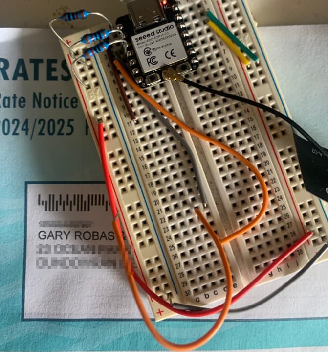
@Dean_Arnold - Unfortunately due to the fact the (internal) pull up resistors are very “weak” (45k), the device is prone to wake from Deep Sleep by external factors.
The pins you have dedicated may have extraneous signals that could cause a wakeup.
I suggest you use your own external pull up resistors (on the column pins) in this case.
If you want to get the GPIO that triggered the wake from Deep Sleep via Ext1 use the following code.
    esp_sleep_wakeup_cause_t wc = esp_sleep_get_wakeup_cause();
    uint32_t gpio_num = 0;
    switch (wc) {
      case ESP_SLEEP_WAKEUP_EXT1:
        {
          uint64_t wakeup_pin_mask = esp_sleep_get_ext1_wakeup_status();
          if (wakeup_pin_mask != 0) {
            gpio_num = __builtin_ffsll(wakeup_pin_mask) - 1;
            PRINTF("Wake up from GPIO %d\r\n", gpio_num);
          } else {
            PRINTF("Wake up from GPIO ???\r\n");
          }
        }
        break;
      default:
        PRINTF("Wake up from unknow source %08X\r\n", wc);
        break;
    }
Here is the output from my test…
14:50:18.669 [03.769] RX> ************************
14:50:18.672 [00.001] RX> * Deep Sleep/Idle Test *
14:50:18.675 [00.002] RX> ************************
14:50:19.670 [00.994] RX> Starting!
14:50:19.672 [00.000] RX> Wake up from GPIO 5
14:50:20.659 [00.986] RX> Tick 1
14:50:21.659 [00.998] RX> Tick 2
14:50:22.659 [00.998] RX> Tick 3
14:50:23.659 [00.999] RX> Tick 4
14:50:24.659 [00.999] RX> Tick 5
14:50:25.660 [00.999] RX> Tick 6
14:50:26.660 [00.999] RX> Tick 7
14:50:27.659 [00.998] RX> Tick 8
14:50:28.659 [00.999] RX> Tick 9
14:50:29.659 [00.998] RX> Tick 10
14:50:29.683 [00.001] RX> Deep Sleep in a sec!
14:50:30.680 [00.996] RX> Going to sleep now
I tried with swapping the rows and columns with the same results. External pullup resistors were required.
Have fun ![]() Gary.
Gary.
1 Like
Thanks for the suggestions. If I add external pull-ups it defeats the need to use the S3 (I was looking to simplify production by using the S3 vs. C3).
It does seem odd that the C3 works perfectly (without the need for pullup resistors, etc.) but the S3 does not. As @PJ_Glasso points out getting these things to sleep and wake is more of an Art than Science.
I have been debugging the code to see if for some reason the pull up resistors are not getting set or held in deep sleep.
I haven’t found anything yet so will try with esp-off code to see if it works properly.
Not giving up yet !
Been playing around as well. No luck. I thought perhaps it was due to the fact that the S3 supports touch capabilities on the GPIOs and the C3 does not. Tried to disable it but no luck. Also tried to add the glitch filter to the GPIOs but didn’t seem to make a difference.
I guess the S3 is far more sensitive to noise, etc. than the C3.
1 Like
@Dean_Arnold - As you mentioned D6 (GPIO 43) is not an RTC pin so can’t be used as such (Column 2).
I’m not sure this could be seen as a “deal breaker”. The row keys that would be allowed to go low from this column being low can’t detect wakes. 8 other keys would work including * and #…
One other thing - you need to use the rtc functions for the RTC
GPIO settings. Eg rtc_gpio_pullup_en
I have tested this scenario here and it works fine.
@grobasoz thanks for coming back to me. I am not sure I completely follow your post. What I did in my code was to essentially swap the columns for rows (from your original code) when going in and out of deep sleep since D6 (CPIO 43) is not a RTC pin (but all the row pins are). Logically I wouldn’t think that would make a difference to the logic/ability to go in and out of deep sleep.
I did use the RTC functions (rtc_io.h) as suggested rather than the GPIO functions (gpio.h) but didn’t make a difference.