I managed to test this with 3 pins, D0, D1, D2 on an ESP32-C6 Dev Kit (I don’t have XIAO ESP32’s) so no need to modify the hardware.
Just a simple software change.
You could use either row or column for the wake as 4 pins can also work.
Power consumption with RTC IO enabled was about 8uA however, but that could be due to other parts on the dev kit I’m using.
Hi there,
The OP does not clearly state C3 or C6 for that matter but if he is using a Xiao ESP32C6 and comparing it to the Dev KitC, Hummm. I would be sure the pins make there way out to the Xiao PIN_sheet you can look at and be a ![]() I think once you look at it you’ll see what I mean.
I think once you look at it you’ll see what I mean. ![]()
I have seen interrupts done with a bit mask register if that’s you’re intimating’s but not on a Xiao ![]()
GL ![]() PJ
PJ ![]()
Even though the thread is C3 ![]()
I have no idea what you mean.
@Dean_Arnold hasn’t specified a device so I can’t cross check pin numbering.
Both XIAO C6 and C6 Dev Kit can use the same pins for this implementation - viz D0, D1, D2 (GPIO 0, 1, 2). Code is interchangeable.
I also don’t understand what is being said or implied here.
ESP32’s support Low Power Wake using RTC_GPIO on EXT1. Doesn’t matter if XIAO or Dev Kit. From the Seeed example…
/*
NOTE:
======
Bit mask of GPIO numbers which will cause wakeup. Only GPIOs
which have RTC functionality can be used in this bit map.
For different SoCs, the related GPIOs are:
- ESP32: 0, 2, 4, 12-15, 25-27, 32-39
- ESP32-S2: 0-21
- ESP32-S3: 0-21
- ESP32-C6: 0-7
- ESP32-H2: 7-14
*/
ESP32-C3 supports many others, viz GPIO0, GPIO1, GPIO2, GPIO3, GPIO4, GPIO5, GPIO6, GPIO7, GPIO8, GPIO9, GPIO10, GPIO11, GPIO12, GPIO13, GPIO14, GPIO15, GPIO16, GPIO17, GPIO18, GPIO19, GPIO20, and GPIO21
HI there,
Exactly, Put more simply. Not all the Pins are available on the Xiao.
HTH
GL ![]() PJ
PJ ![]()
Say’s it right there as well,
Just for clarification I did specify in my original post that I am using the XIAO ESP32C and of course the title of the thread is about waking up a XIAO ESP32C.
@PJ_Glasso thanks for the thoughts on using diodes and a pulldown resistor. This is a great lead and I shall have a try. Studying the Keypad.h library, row pins are set to INPUT_PULLUP and column pins to OUTPUT. My current pin mapping looks like this:
const byte ROWS = 4; //keypad four rows
const byte COLS = 3; //keypad three columns
char keys[ROWS][COLS] = {
  {'1','2','3'},
  {'4','5','6'},
  {'7','8','9'},
  {'*','0','#'}
};
byte rowPins[ROWS] = {D5, D0, D1, D3}; //connected to the row pinouts of the keypad
byte colPins[COLS] = {D4, D6, D2}; //connected to the column pinouts of the keypad

Keypad keypad = Keypad(makeKeymap(keys), rowPins, colPins, ROWS, COLS);
1 Like
So, something like this:
I recognize it won’t wake on any key pressed (but most of them). Not enough RTC pins available–I would need to use an XIAO ESP32S to wake on any key.
1 Like
Thanks - that makes more sense…
Hi there,
You got it, I would see if you can get the “star” key most gate automated systems wake up if you press the star. So there’s that ![]()
but I do also see there’s always that one egghead that smashes all the keys like a spazoid. So I vote “Star” ![]()
GL ![]() PJ
PJ ![]()
I am beginning to lose hope…quickly coming to the conclusion that it just isn’t possible. I wired it up per my diagram and included the following code which is called after 60 seconds of inactivity:
//Routine to put the MCU into deep sleep
void enterDeepSleep() {

  // Configure RTC wake-up source, D0 GPIO2 is the dedicated wakeup pin
  esp_deep_sleep_enable_gpio_wakeup(BIT(D0), ESP_GPIO_WAKEUP_GPIO_HIGH);  //also have tried LOW

  Serial.println("Going to sleep now... Press any key to wake up!");
  Serial.flush();
  delay(100);
  esp_deep_sleep_start();
}
…and no luck. It goes to sleep but never wakes up. Maybe I will have to settle for an additional button dedicated to waking the unit up…but with all those other buttons it seems superfluous.
This “wired or” approach normally works well.
A couple of checks.
Is the keypad actually causing the interrupt pin to be pulled low? Can you measure with a scope or multimeter?
What are the non diode outputs set to? They should be driven low.
If that’s all ok, perhaps prior to calling the sleep enable, set the D0 mode to INPUT?
Hi there,
So I have this running in the video, Sleeps and wakes up BSP 3.1.1
good to go using the GPIO…
The ESP32C3 uses ESP_SLEEP APIs, but the function esp_sleep_enable_ext0_wakeup() is not always available in some ESP32 variants (especially ESP32C3). The correct way for GPIO wake-up on the ESP32C3 is to use esp_deep_sleep_enable_gpio_wakeup(), which you originally had in your code.
#include <Adafruit_NeoPixel.h>
#include <esp_sleep.h>

// Define pin connections
#define LED_PIN    2   // WS2812 connected to D0 (GPIO2)
#define BUTTON_PIN 3   // Button connected to D1 (GPIO3)
#define NUM_LEDS   8   // Total WS2812 LEDs

Adafruit_NeoPixel strip(NUM_LEDS, LED_PIN, NEO_GRB + NEO_KHZ800);

void enterDeepSleep() {
    Serial.println("Entering deep sleep... Press the button to wake up.");
    Serial.flush();
    delay(100);

    // Configure D1 (GPIO3) as the wake-up source
    esp_sleep_enable_ext0_wakeup((gpio_num_t)BUTTON_PIN, HIGH);  // Wake on HIGH

    // Enter deep sleep
    esp_deep_sleep_start();
}

void setup() {
    Serial.begin(115200);
    strip.begin();
    strip.show(); // Initialize all LEDs to OFF

    pinMode(BUTTON_PIN, INPUT_PULLDOWN);
}

void loop() {
    static int ledIndex = 0;

    if (ledIndex < 5) {  // Light up 5 LEDs, one at a time
        strip.setPixelColor(ledIndex, strip.Color(0, 255, 0)); // Green color
        strip.show();
        Serial.print("Lighting LED: ");
        Serial.println(ledIndex);
        delay(1000); // Wait 1 second
        ledIndex++;
    } else {
        enterDeepSleep();  // After 5 LEDs are lit, enter deep sleep
    }
}
Serial output…
Lighting LED: 0
Lighting LED: 1
Lighting LED: 2
Lighting LED: 3
Lighting LED: 4
Entering deep sleep... Press the button to wake up.
Waking up from Deep Sleep...
Lighting LED: 0
Lighting LED: 1
Lighting LED: 2
Lighting LED: 3
Lighting LED: 4
Entering deep sleep... Press the button to wake up.
Video…

Powers on
![]() Each time the loop runs, one WS2812 LED lights up (Green).
Each time the loop runs, one WS2812 LED lights up (Green).
![]() After the 5th LED lights up, the ESP32C3 goes into deep sleep.
After the 5th LED lights up, the ESP32C3 goes into deep sleep.
![]() Pressing the button on D1 (GPIO3) wakes up the device.
Pressing the button on D1 (GPIO3) wakes up the device.
![]() After wake-up, the sequence starts over.
After wake-up, the sequence starts over.
Setup inits the GPIO as the Wakeup call.
HTH
GL ![]() PJ
PJ ![]()
- Replaced
esp_sleep_enable_ext0_wakeup()withesp_deep_sleep_enable_gpio_wakeup() - This is the correct method for ESP32C3 GPIO wakeup.
- It will wake up when D1 (GPIO3) is pulled HIGH.
- Added
esp_sleep_get_wakeup_cause() - Now, after waking up, the Serial Monitor will print “Waking up from Deep Sleep…”.
- Added
INPUT_PULLDOWNtoBUTTON_PIN - Ensures that GPIO3 stays LOW when not pressed, preventing false wake-ups.

@PJ_GLass I very much appreciate the help. However, I fear we are in jeopardy of going around in circles. You rightly point out the C3 needs to use the esp_deep_sleep_enable_gpio_wakeup() function…which is what I am using. However, your example code then uses esp_sleep_enable_ext0_wakeup((gpio_num_t)BUTTON_PIN, HIGH); ???
And I know I am sounding like a broken record but the problem has never been waking up the ESP with a simple button. That’s a piece of cake. The issue is using an array of buttons that are connected in a matrix.
In that scenario a single button does not go high or low. Rather, when a button is pressed an impedance of about 200 ohms appears between the corresponding column pin and row pin.
As mentioned, as much as I hate to give up, I just can’t see a way to get the keypad to wakeup the ESP32C3.
1 Like
SO I asked AROUND" ![]()
![]()
AH’ Ah, I see the challenge more clearly now. In a 3×4 keypad matrix, no single pin goes high or low by itself when a key is pressed—instead, a conductive path forms between a row and a column. This makes it tricky to trigger a GPIO wake-up since ESP32C3 normally expects a direct HIGH or LOW transition.
Have you tried the last item?
![]() Solution: Using a Capacitor + Diodes to Hold Wake-Up Signal
Solution: Using a Capacitor + Diodes to Hold Wake-Up Signal
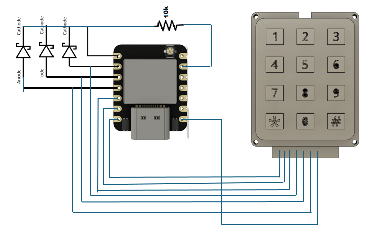
Since pressing a key creates a low-resistance connection (≈200Ω) between a row and a column, we can use a diode network to OR all columns into a single wake-up line. A capacitor then holds this wake-up signal long enough for the ESP32C3 to wake up and scan the matrix. ?
 How This Works
- Each column is connected to a diode (e.g., 1N4148) leading to a single wake-up pin (GPIO_WAKEUP).
- A pull-down resistor (10kΩ) keeps the wake-up pin LOW when no key is pressed.
- A capacitor (10nF - 100nF) between GPIO_WAKEUP and GND holds the signal momentarily when a key is pressed.
- Once awake, the ESP32C3 scans the matrix normally to determine which key was pressed.
 Wiring Diagram
 Components Needed
- 3×4 keypad matrix
- 6x diodes (1N4148)
- 1x pull-down resistor (10kΩ)
- 1x capacitor (10nF - 100nF)
Connections
| Keypad Pin | ESP32C3 Pin |
|---|---|
| Row 1 (R1) | GPIO2 (D0) |
| Row 2 (R2) | GPIO3 (D1) |
| Row 3 (R3) | GPIO4 (D2) |
| Column 1 (C1) | GPIO5 (D3) via diode to GPIO_WAKEUP |
| Column 2 (C2) | GPIO6 (D4) via diode to GPIO_WAKEUP |
| Column 3 (C3) | GPIO7 (D5) via diode to GPIO_WAKEUP |
| Column 4 (C4) | GPIO8 (D6) via diode to GPIO_WAKEUP |
- Wake-Up Pin → GPIO9 (D7)
- Diodes: Each column is connected through a diode to GPIO9 (D7).
- Capacitor: 10nF - 100nF between GPIO9 (D7) and GND.
- Pull-down resistor: 10kΩ between GPIO9 (D7) and GND.
 Explanation
- When a key is pressed, it creates a path between a column and a row.
- The diodes OR all columns into a single wake-up signal (GPIO9).
- The capacitor holds the wake-up pulse long enough for the ESP32C3 to register it before it discharges.
- Once the ESP wakes up, it scans the matrix as normal.
Here is the code Suggested, as well. Can’t hurt to try . some SMD components you won’t even notice.
#include <Wire.h>
#include <Keypad.h>
#include <esp_sleep.h>

#define WAKEUP_PIN 9  // GPIO9 (D7)

// Keypad configuration
const byte ROWS = 3;
const byte COLS = 4;
byte rowPins[ROWS] = {2, 3, 4};  // D0, D1, D2
byte colPins[COLS] = {5, 6, 7, 8}; // D3, D4, D5, D6

char keys[ROWS][COLS] = {
  {'1', '2', '3', 'A'},
  {'4', '5', '6', 'B'},
  {'7', '8', '9', 'C'}
};

Keypad keypad = Keypad(makeKeymap(keys), rowPins, colPins, ROWS, COLS);

void enterDeepSleep() {
    Serial.println("Going to deep sleep...");
    esp_deep_sleep_enable_gpio_wakeup(BIT(WAKEUP_PIN), ESP_GPIO_WAKEUP_GPIO_HIGH);
    Serial.flush();
    delay(100);
    esp_deep_sleep_start();
}

void setup() {
    Serial.begin(115200);

    pinMode(WAKEUP_PIN, INPUT_PULLDOWN);  // Wake-up pin setup

    if (esp_sleep_get_wakeup_cause() == ESP_SLEEP_WAKEUP_GPIO) {
        Serial.println("Waking up from deep sleep...");
    } else {
        Serial.println("Cold boot...");
    }
}

void loop() {
    char key = keypad.getKey();

    if (key) {
        Serial.print("Key Pressed: ");
        Serial.println(key);
        delay(500);
    }

    // Enter deep sleep after no input for 10 seconds
    static unsigned long lastPress = 0;
    if (millis() - lastPress > 10000) {
        enterDeepSleep();
    }
}
HTH
GL ![]() PJ
PJ ![]()
 Summary
![]() Diodes OR all columns into a single wake-up signal.
Diodes OR all columns into a single wake-up signal.
![]() A capacitor holds the signal long enough for ESP to wake up.
A capacitor holds the signal long enough for ESP to wake up.
![]() ESP scans the matrix normally once awake.
ESP scans the matrix normally once awake.
![]() Low-power, simple, and effective solution.
Low-power, simple, and effective solution.
This should work perfectly! ![]()
I can confirm that the original method I proposed works on a XIAO ESP32C3.
I managed to secure a keypad and XIAO ESP32C3 (despite Cyclone Alfred interruptions) and test the deep sleep gpio wake theory.
3x Columns are on GPIO 2, 3 and 5.
4x Rows are on GPIO 4, 6, 7 and 21.
Every key works to wake the ESP32-C3. Not need for diodes, pullups etc.
I have to go out now but will write up the code and post here if you are interested.
@grobasoz Yes, definately! If you can make this work with just software that would be fantastic. I thought I have tried every permutation but maybe not.
Just as an aside, the specific keyboard I am using is 3x4 Keypad
I bought a simple cheap keypad as I’m away from my office/workshop so no soldering etc.

I wired the XIAO ESP32C3 with (male/male) Dupont wire taped in place on the XIAO
I started with the Adafruit Keypad library example and checked wiring and keymap before adding Deep Sleep code (see #define USE_DEEP_SLEEP).
The columns are on RTC GPIO’s and with a sleep enable setting of ESP_GPIO_WAKEUP_GPIO_LOW, the columns are pulled high (internally) when the esp_deep_sleep_enable_gpio_wakeup function is called.
Multiple GPIO can wake the ESP32C3 by setting the appropriate bit mask (COL_PIN_MASK).
The rows’ state needs to be retained (LOW) during deep sleep and released at wake for the keypad library to work. When a button is pressed the associated (HIGH) column is pulled low for the wakeup.
Since the serial disconnects during deep sleep it’s a little tricky to detect the key presses using print statements. I’ll try with an OLED display if time permits.
I have a 5 second delay before sleep to allow programming - this is reset every key press so allows the device to be detected for programming by pressing a key repeatedly.
1 Like
Hi there,
I would agree for sure a total software solution would be the most desirable, The Bit Mask @grobasoz pointed out should work and imo would be the best, but also a Heads up on the keyboard link some user reported the pinout is incorrect? It’s a funny challenge, I thought it would be easier. ![]()
I’m more surprised that Keypad.h doesn’t already have something like or for it.? ![]()
GL ![]() PJ
PJ ![]()
@grobasoz I am truly humbled…you cracked the code! I previously played around with gpio_hold_dis and gpio_hold_en to prepare the C3 for both wakeup and sleep but obviously without success.
I am now planning on using the XIAO ESP32S3 which gives me more flexibility with pin mappings allowing me to more easily mount the MCU directly on the back of the keyboard. Haven’t tried it yet but I assume I would just need to replace:-
if (esp_deep_sleep_enable_gpio_wakeup(COL_PIN_MASK, ESP_GPIO_WAKEUP_GPIO_LOW) == ESP_OK)
with:-
if (esp_sleep_enable_ext1_wakeup(COL_PIN_MASK, ESP_EST1_WAKEUP_ANY_LOW) == ESP_OK)
Thank you so much!
1 Like
@Dean_Arnold, @PJ_Glasso, and everyone. Hi, my name is Aaron and I am new to this. I have a XIAO ESP32C3 board and I want to wake it up from deep sleep using the following TWO ways:
(1) Pressing on a tactile push button connected to GPIO4 (to read LOW), and
(2) Reading HIGH from a plug detection voltage divider circuit (5VUSB → 200K ohm → GPIO3 → 200K ohm → GND) connected to GPIO3 to detect if USB is plugged into the board.
However, there is a limitation that external wakeup (neither ext0 nor ext1), i.e. esp_sleep_enable_ext1_wakeup(), is not available for XIAO’s ESP32C3 boards! It might be available to other brands but the affordable XIAO ESP32C3 board limits to only GPIO wakeup.
In addition, a second limitation is that I can only call esp_deep_sleep_enable_gpio_wakeup() once with second argument being either ESP_GPIO_WAKEUP_GPIO_LOW or ESP_GPIO_WAKEUP_GPIO_HIGH, which is pretty sad to be honest.
Is there a way I could wake up my XIAO ESP32C3 board using more than one pin?
Turns out that I might need to modify my circuit, by adding an OR logic circuit connecting that switch and plug detection circuit that I mentioned, and read LOW from the output of that OR circuit (must use a separate GPIO pin to read such signal). A little clumsy but it is what it is I guess. But if anyone could think of a software/coding workaround you’d be my life saver :)) really can’t think of any software approach at this moment.