In deep sleep mode on XIAO ESP32C3 I can use a timer to wake up the XIAO from deep sleep every x seconds, check this example. The power consumption during deep sleep is an astonishing ~41uA (great success in Borats voice).
But in my case I need to wake up the XIAO from DEEP sleep using external sources. I came across this official documentation by espressif. The line that says ESP32C3 can’t be woken up from deep sleep using EXT0 and EXT1 as the case with the standard ESP32 killed my project in its crib ![]()
Is there any other ways to wake up the board from deep sleep using external triggers? Should I give up and choose some other processor, like the standard ESP32?
Did you ever find a solution for this? I’m reading the same thing you are and coming to the same conclusion. The only idea I have is to use an external trigger to power on the entire chip (FET + dry contact?) but that won’t work for all use cases.
Same question here. Is it possible to use the JTAG pad “EN” for this purpose. According to the Eagle schematic the Reset button is coupled by a 10K resistor to VCC 3.3v and attached to the CHIP_EN pin of the espressif chip, and the other side attached to ground. VCC and Ground are coupled with a 100nF capacitor.
Can you solder/connect the same setup on the “EN” JTAG pad ? Anyone tried that ?
Hello,
I haven’t been working on the project since christmas ![]() I really don’t remember if I solved the isse with external interrupts, All I remember that it is possible to wakeup from deepsleep using external source, but can’t provide further info. All what I could find in my Code folder was this below, which I copied from somewhere (Don’t even remember from which website) you may try it, if it works. I will come back here to leave a reply if I resumed working on the project and got new expreince
I really don’t remember if I solved the isse with external interrupts, All I remember that it is possible to wakeup from deepsleep using external source, but can’t provide further info. All what I could find in my Code folder was this below, which I copied from somewhere (Don’t even remember from which website) you may try it, if it works. I will come back here to leave a reply if I resumed working on the project and got new expreince
#include "hal/gpio_types.h"
#include "esp_err.h"
#include "esp_sleep.h"
#define uS_TO_S_FACTOR 1000000ULL  //Conversion factor for micro seconds to seconds
#define TIME_TO_SLEEP 20           //Time ESP32 will go to sleep (in seconds)
#define rLed D0                    //red
#define yLed D1                    //yellow
#define gLed D2                    //greed (this should not blink as the board should be in sleep mode)

struct Button {
  const uint8_t PIN;
  uint32_t numberKeyPresses;
  bool pressed;
};

Button button1 = { D6, 0, false };

//variables to keep track of the timing of recent interrupts
unsigned long button_time = 0;
unsigned long last_button_time = 0;

void IRAM_ATTR isr() {
  button_time = millis();
  if (button_time - last_button_time > 250) {
    button1.numberKeyPresses++;
    button1.pressed = true;
    last_button_time = button_time;
  }
}

void setup() {
  Serial.begin(115200);
  pinMode(button1.PIN, INPUT_PULLUP);
  attachInterrupt(button1.PIN, isr, FALLING);
  esp_sleep_enable_ext0_wakeup(GPIO_NUM_21, 1);
}

void loop() {
  if (button1.pressed) {
    Serial.printf("Button has been pressed %u times\n", button1.numberKeyPresses);
    button1.pressed = false;
  }
}

void led_Flash(uint16_t flashes, uint16_t delaymS) {
  uint16_t index;
  for (index = 1; index <= flashes; index++) {
    digitalWrite(LED1, HIGH);
    delay(delaymS);
    digitalWrite(LED1, LOW);
    delay(delaymS);
  }
}```hi there,
i was struggeling with the external deep sleep too on my xiao esp32c3 and a touch-button, and finally got it working
after lots of searching i found that the code needs a bitmask of the pin number, not the pin number or gpio number
for pin gpio3 it translated to: 1ULL << 3
in the below code i got a fairly long delay wich is only to give me more time to upload changes without pushing buttons so you can totally ignore those delays…
hope this helps.
this is the sleep related code i use in my sketch: (not my complete code)
#define   TouchPin  GPIO_NUM_3

void setup() {
  pinMode(TouchPin,  INPUT);
}

void gotoSleep() {
  Serial.println("going to sleep in 30 sec....");
  delay(30000);
  esp_deep_sleep_enable_gpio_wakeup(1ULL << 3,ESP_GPIO_WAKEUP_GPIO_HIGH);
  Serial.println("going to sleep now");
  delay(1000);
  esp_deep_sleep_start();

}
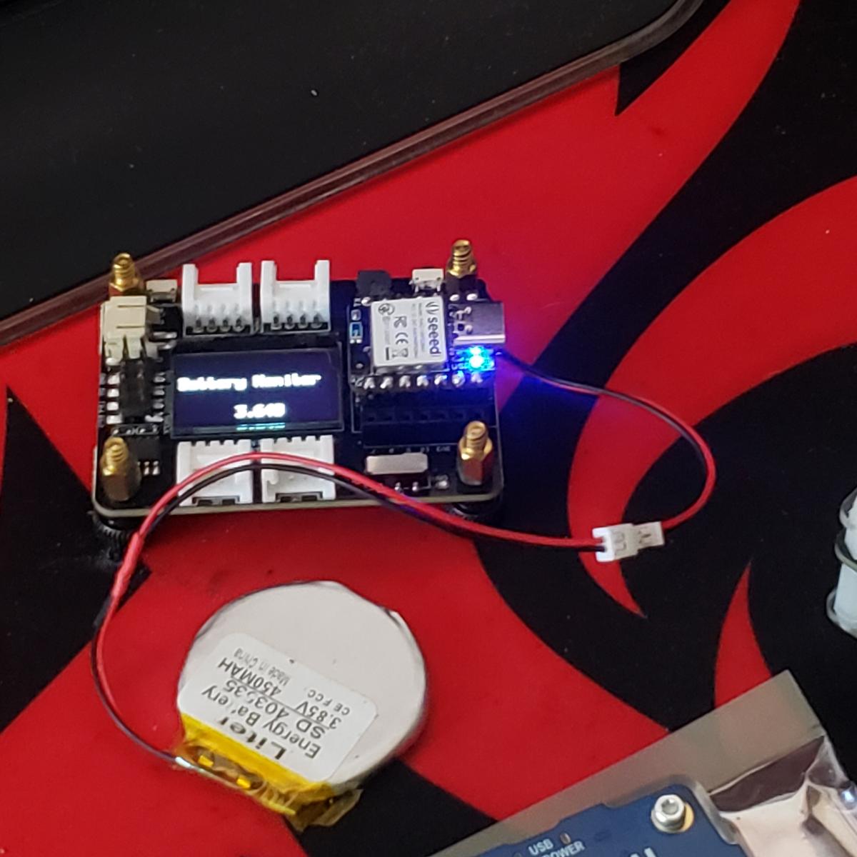
I have the C3 working as a nice low powered sensor using D0 as the battery monitor, D1 as a binary sensor (w/external pullup - using for a reed switch), D2 and D3 are interrupt sources. Here is the code snippet I use to enable the ints:
…
esp_deep_sleep_enable_gpio_wakeup((1ULL << 4), ESP_GPIO_WAKEUP_GPIO_HIGH);
esp_deep_sleep_enable_gpio_wakeup((1ULL << 5), ESP_GPIO_WAKEUP_GPIO_HIGH);
esp_sleep_enable_timer_wakeup(config.sleeptime * (unsigned long)1000000);
Serial.flush();
esp_deep_sleep_start();
On interrupt I test the source and act accordingly:
gpio_reason = esp_sleep_get_gpio_wakeup_status(); // C3
motion = 0;
motion |= (gpio_reason & 0x20) ? 0x3 : 0; // Activity on 4 - includes motion error bit
motion |= (gpio_reason & 0x10) ? 0x4 : 0; // inactivity on 5
sendStatus();
This seems to work for me. I’m using the ints from an ADXL345 for activity and inactivity
Wow, Nice It’s like a BLE Sense with WIFI ![]() Great stuff.
Great stuff. ![]()
You get any power measurement’s?
I’m attempting the same with the Xiao BLE Sense and its LSM6DS3
using it’s interrupts and low power modes.( I’m NOT streaming the imu data just using Accel readings for sensing motion ie. being picked up. BLE connected , Phone app sends Enable /Disable , reads battery level char , tap detection and Drop or fall detect may Actually mean free-fall detect. (it’s not the fall that kills , It’s that sudden STOP ! ![]()
Curious what kinda LOW power numbers can be achieved.
GL ![]()
Thanks. I haven’t measured the actual current in deep sleep, but it should be well under 100pa with the adxl in auto standby and the Serial disabled. As long as it’s running “stone cold” I’m happy.
I still prefer the Sense for wearables because of its all-in-one. With a small 100ma Lipo it still would be good for many days between charges, comparable to any typical wearable.
You’re right on the hit after the fall…lol.
Right! :-),
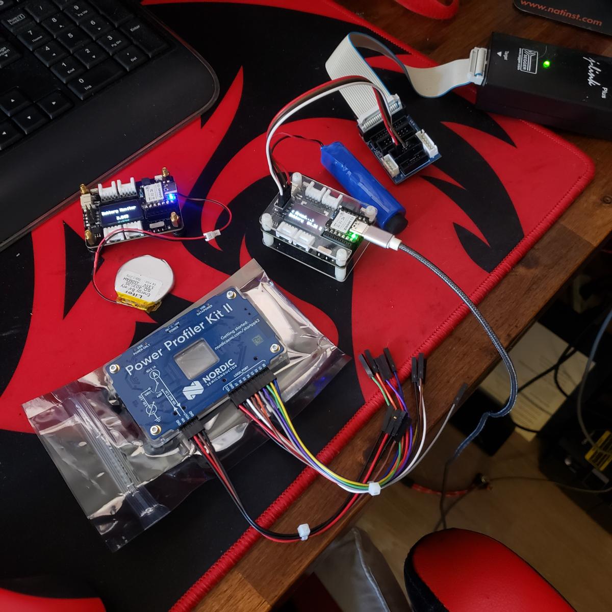
Well I just picked up a PowerProflier Kit II so I’ll be taking some measurements on this exactly and report any findings. Lots of general stuff out there but thin on any correlation to running code and real word numbers. Simple stuff like the BLE Peripheral and Central example’s as is power baseline profile., It’s a starting point at a minimum. SeeedSudio would be benefactor’s no doubt. Alll the Nordic stuff is geared to there SDK so it’s minimally helpful imo.
I’m trying to switch modes from (motion Sensitivity) to double tap detection with imu on the fly. Ultimately changing it via BLE app.
Onwards… ![]()
GL ![]()

I want to invent something and get one of theses…LOL

Have Fun.
Can you post the complete code which worked for you? Like I have been looking for a solution for a while now but no success getting the correct code.
Here is code I’m using to test the battery and multiple buttons. Works well.
#include "WiFi.h"
#include <PubSubClient.h>

#define DEBUG_ENABLED 0

const char* ssid     = "DronesAreWatching";
const char* password = "";

const char* mqtt_server = "blue.home";
const char* mqttUser = "internal";
const char* mqttPassword = "";


void debug(String msg){
  if (DEBUG_ENABLED){
    Serial.println(msg);
  }
}

WiFiClient espClient;
PubSubClient client(espClient);

void setup_wifi() {
  delay(10);
  // We start by connecting to a WiFi network
  debug("Connecting to ");
  debug(ssid);

  WiFi.begin(ssid, password);

  while (WiFi.status() != WL_CONNECTED) {
    delay(500);
    debug(".");
  }

  debug("WiFi connected");
  debug("IP address: ");
  // debug(WiFi.localIP());
}

void setup() {
  if (DEBUG_ENABLED){
    Serial.begin(115200);
    delay(100);
  }

  pinMode(D0, INPUT_PULLUP);
  debug("Startup...send message");

  setup_wifi();

  client.setServer(mqtt_server, 1883);
  client.connect("ESP8266Client", mqttUser, mqttPassword);

  uint64_t gpio_reason = esp_sleep_get_gpio_wakeup_status();
  debug(String(gpio_reason));
  int GPIO = 0;
  if (gpio_reason > 0){
    GPIO = log(gpio_reason)/log(2);
  }
  debug(String(GPIO));


  String GPIOString = String(GPIO);
  int str_len = GPIOString.length() + 1;
  char char_array[str_len];
  GPIOString.toCharArray(char_array, str_len);

  client.publish("mouse/trigger", char_array);


  esp_deep_sleep_enable_gpio_wakeup((1ULL << 2), ESP_GPIO_WAKEUP_GPIO_LOW);  //GPIO2
  esp_deep_sleep_enable_gpio_wakeup((1ULL << 3), ESP_GPIO_WAKEUP_GPIO_LOW);  //GPIO3

  debug("Going to sleep in 5 seconds"); //time to send message
  delay(5000);

  if (DEBUG_ENABLED){
    Serial.flush();
  }
  esp_deep_sleep_start();
}

void loop() {
}
Is it possible to wake-up the XIAO ESP32C from deep sleep with a 3x4 Matrix Keypad? I have a battery powered XIAO ESP32C that uses a keypad and ESP-NOW for communications as a remote control. Ideally I would like it to wake-up from deep sleep when any key on the keypad is pressed (although I would settle with just one of the keys).
So far I have yet to figure out how to do it using something like:
esp_deep_sleep_enable_gpio_wakeup(BIT(D1), ESP_GPIO_WAKEUP_GPIO_LOW);
Where D1 is one of the rowPins on the keypad. If I manually connect D1 to ground it wakes-up but not through the keypad.
Hi there,
and Welcome Here…
You have a PIC of the Apparatus… ![]()
Is this a Uart situation? You can use the receive data interrupt (dataAvailable) to wake it if so, a Key Matrix? has to be some latch somewhere to use maybe? You just need a always HIGH , or LOW, or and Edge trigger I would think.
HTH
GL ![]() PJ
PJ ![]()

Hi there,
Sure the old 3X4 row matrix (7 inputs , perfect for the Xiao).
Pins 2,3,4 then Pins 5,6,7,8, Using the Keypad.h provides for The Keypad library provides functions like getKey() to check for button presses and getChar() to return the character associated with the pressed button. can’t detect a two button press though AFAIK?
HTH
GL ![]() PJ
PJ
there’s a MAtrix keypad demo, so look at that. (may be for a shield)?
I have no problems using the Keypad library and everything works fine. However, I am now trying to add the capability of waking up the XIAO32 when I place it in deep sleep by pressing one or more keys on the keypad (to bring it out of deep sleep). After trying various approaches, I have now turned to the forum in hopes someone has cracked it.
Hi there,
Do you have a schematic of how it;'s connected or a picture of it all connected? If you attach a Pin # to the wakeup for deep sleep it has to be a Pin thats powered by the LPc or LPRTC the only controller That is alive in deep sleep it’s waiting for the pin to CHANGE state.
HTH
GL ![]() PJ
PJ ![]()
I am not sure a schematic would really help here. It couldn’t be more simple. The 7 pins on the 3x4 matrix are connected to 7 pins on the XIAO-ESP32 (D0 - D6).
Switches connected in a matrix do not work the same as a single button. In a matrix configuration two pins are needed to determine which button has been pressed. This is the fundamental problem I have run into. The Keypad.h library constantly scans the seven pins for a change in two corresponding pins…so far I have not found a way to replicate this to cause the ESP to wake up (since the ESP is expecting a pin change on a single pin…not two in conjunction).
Have a look at this blog. It may be possible using the ext1 interrupt?
Edit> Alternatively this one from Seeed Wiki.
I tested this and it works on an ESP32-C6.
Hi there,
SO yes. a couple ways since the issue is that the ESP32C3 wake-up from deep sleep typically works with a single pin, but a 3×4 matrix keyboard requires multiple pins to detect key presses.
- In a keypad matrix, the rows are usually set as outputs and the columns are inputs (or vice versa).
- Detecting a key press requires scanning the matrix, which isn’t possible when the ESP32C3 is in deep sleep.
- ESP32C3 wake-up sources (RTC GPIOs) only allow waking up from a single pin change, not a combination of two pins.
For the ESP32C3 to wake up on any key press, we need to detect a keypress with a single interrupt signal. Here are some solutions:
- Use External Pull-Down Resistors and OR the Signals (Best for Simplicity)**
Concept:
- Connect diodes from each column to a single wake-up pin.
- When a key is pressed, the corresponding column pulls the wake-up pin HIGH, waking up the ESP.
Wiring:
- Place Schottky diodes (e.g., 1N4148) from each column pin (Pins 5,6,7,8) to a dedicated wake-up pin (e.g., Pin 9).
- Use an external pull-down resistor (10kΩ) on the wake-up pin to keep it LOW when no key is pressed.
Works with ESP32C3’s single-pin wake-up.
![]() No firmware modification needed for wake-up.
No firmware modification needed for wake-up.
![]() Efficient and simple hardware fix.
Efficient and simple hardware fix.
You can go Hardcore on it too,
- Use a small microcontroller (like an ATtiny) or an I/O expander (PCF8574) to monitor the keypad matrix.
- When a key is pressed, the microcontroller/IC sends a single interrupt signal to the ESP32C3.
- ESP32C3 wakes up and scans the keypad normally.
Use a Capacitor to Hold the Wake-Up Signal Until ESP Wakes Up
- Connect all columns to a single wake-up pin through a diode circuit.
- Use a small capacitor (10nF - 100nF) to hold the HIGH signal long enough for ESP32C3 to wake up and scan the matrix.
Passive and Low power…
just some food for thought.
HTH
GL ![]() PJ
PJ ![]()
you could just add a wire to another IO pin and use a specific key.?