Hi ,
I have an Expansion Board Base for XIAO with a esp32c3 where a lipo battery is connected. On which pin can I read the battery charge (percentage or voltage) knowing that the GPIO A0 input is already taken by a sensor.
Thanks,
Emmanuel
Hi ,
I have an Expansion Board Base for XIAO with a esp32c3 where a lipo battery is connected. On which pin can I read the battery charge (percentage or voltage) knowing that the GPIO A0 input is already taken by a sensor.
Thanks,
Emmanuel
Welcome!


Hi @cgwaltney , thanks for the diagrams, my problem is that I’d like to measure the battery voltage to know when to charge it. I’d like to know if the Expansion Board has a line connected to the GPIO to see the battery voltage, or do I have to measure it another way?
Thanks
You have to do it another way… The Battery Charging Circuit is not “Smart” we are wishing for this in future revisions
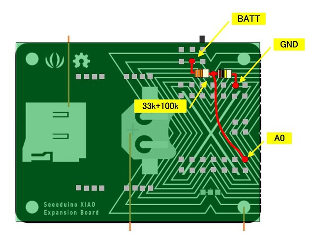
I would think you should bring a line from the battery + over to an Analog Pin… you can use A0 if you are not using the A0 Grove Port You may need a diode or small resistor to make sure you do not accidentally overvolt the pin
Hi there,
So what @cgwaltney suggests works and This Thread here is a good work.
just to add to the suggestion pile.
HTH
GL ![]() PJ
PJ ![]()
Hi Emmanuel_COLUSSI,
This may be helpful.
Hi ,
thank you all for your suggestions, I’m going to test what @cgwaltney suggests, I’ll keep you informed.
Emmanuel
Thank you all!
I applied the solution using a voltage divider as suggested here, connected to the A1 input. It’s a pity this feature isn’t directly available on the Expansion Board.
HI there,
Yea we are looking for an UPDATE to the Dev board… This should be added to the next rev for sure. Hilarious , Battery powered devices but you can’t measure battery percentage…
things like ![]() a POWER switch, UpGradable DIsplay, SWD and JTAG (compatible) for all of Seeed’s Xiao’s, a SOCKET for the Xiao, I2S audio amp & headphone Jack, 3D printable Stand or enclosure and more.
a POWER switch, UpGradable DIsplay, SWD and JTAG (compatible) for all of Seeed’s Xiao’s, a SOCKET for the Xiao, I2S audio amp & headphone Jack, 3D printable Stand or enclosure and more.![]()
GL ![]() PJ
PJ ![]()
is there still no no-soldering solution to measure the battery voltage for the built-in battery port?
I have a single lipo cell connected and need to tell the user the current battery level.
If I need to solder, what resistor value do I need to use? SW guy here ![]()
Hi there,
LOL… Yea there is a WiKi page with a picture of them soldered. So I thought, but on the bottom of the dev board , my Google PHY located the thread with picture…
HTH
GL ![]() PJ
PJ ![]()
if you google this exact phrase" reading Battery level on the Xiao Expansion Board Base resistors " switch to Image view you’ll get more than enough info to conquer the Xiao Battery World forsure ![]()
Thanks so much, I used 47k and 100k resistors and adjusted the formula accordingly, it works perfect now.
Still, a big shame for Seeed to not do this onboard!!
I made a Meshtastic node based on the Xiao ESP32-S3 module, and of course, there is no battery voltage measurement… If I connect it as described above, that is, battery voltage through a resistor divider to Pin A0, should I see the battery voltage in the Mashtastic app?
Hi there,
Good Question? It would be there, but what is the GPIO that will be used as a ADC input or battery input , is it exposed in the apps menu, like the messaging stuff ? or the Display settings are?
HTH
GL ![]() PJ
PJ ![]()
I’m asking about the Meshtastic software, the standard software, because I don’t know if it’s software-based.
I can do a hardware upgrade, but I don’t know if the Meshtastic version for this module will support it and show the voltage in the app.
Hi there,
Ok , so I looked around and I See this info.
The standard Meshtastic battery reading system works by using an internal voltage divider circuit connected to an Analog-to-Digital Converter (ADC) pin on the microcontroller. This setup allows the device to measure the voltage of the connected battery and report it via the Meshtastic app and display.
How the battery reading works
ADC_MULTIPLIER to calculate the actual battery voltage. This multiplier accounts for the voltage division ratio caused by the resistors. This is why calibration is often needed for accuracy.GPIO pins used for battery monitoring
The specific GPIO pin used for battery monitoring depends on the board and its hardware design. This is defined in the device’s firmware and schematics. Here are some examples for popular Meshtastic-compatible boards:
To find the specific GPIO pin for any given board, you should consult its schematic diagram or the device_variant file in the Meshtastic firmware source code.
So looks like some of this you have already addressed so , find out what IO pin does the job and connect it to that should yield good results. ![]()
HTH
GL ![]() PJ
PJ ![]()
Thank you for explaining the topic. The measurement principle, GPIO connection, and operation are clear to me.
I don’t have the source version of the Mastastic firmware for the Xiao ESP32 S3, and I don’t know if it’s included in the program or for which GPIO port.
I may not have described it precisely at the beginning, but that’s my main problem.
As you wrote, other board versions have different solutions and use different GPIO ports, and this is included in the program.
The XIAO ESP32S3 board doesn’t have hardware support for measuring battery voltage, so I can do that, but it still needs to be included in the firmware. Is it?
If so, which GPIO pin?