really having not much luck with this sensor so far. I tried all the hookup possible, uart, I2C and now spi. Tried all the library you can find on the internet and the esp cant detect it.
any idea ?
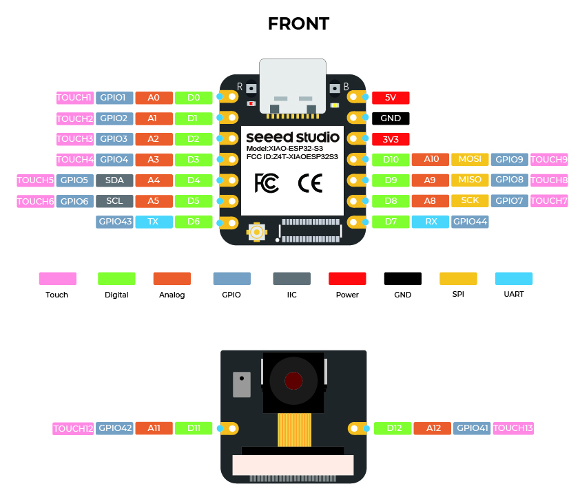
i use a micro sd module with SPI as well and its works perfectly fine so the SPI communication works. The Pn532 is hooked up on same line except the SS pin which uses the D3 pin.
Hi there,
Hilarious,
You could have opened with that… It not the same as in Arduino I can assure you… LOL
In a nut shell , Older demo’s and some legacy LIB only work with the older ESP board support files under the boards tab in arduino. You can pull down a menu and load the older frameworks etc. from the manufactures Board Support Package. Recently ESpressif, Changed there’s to be compatible with the Newer IDF they put out. and stuck it to the Arduino IDE LOL,
Now for some demo’s they only work with the older BSP and certain LIB’s
In PLatform.io it’s done differenly if you need the older BSP to make your thing go, because it’s from a demo from 2015
anyway @ maxgerhardt puts it better than anyone and it works very well. Here
go read the , This, This , This and This links embedded to gain GURU status.
HTH
GL PJ
have you tried it in arduino to see if rolling it back makes it compile and work. Try that first is my .02
from 3.0.2 to say 2.1.7 ?
i tried connecting it with I2c and with an i2c scanner i detect it but cant make it work with the library right now…
what i dont understand is : in the constructor of the object with the adafruit library you need to pass in paramater the irq pin and the reset pin. But i read that with I2c its optional. theres no way to pass the adress. how would i solve that ?
Hi there,
Post the code your using, Please use the code tags above “</>” paste it in there.
We can look , And Yes you can pass those pin assignments and is the case in allot of older code being brought forward to newer syntax. No big deal.
HTH
GL PJ
good the scanner see’s it so just a matter of getting the pins correct and you can try the GPIO pin numbers instead of the logical numbers.
ie. if your using PIN 2 for example (D1) the code should reference GPIO2 if you get that. (D2) would be GPIO3…and so on.
ahahahah, i dont know. im trying to figure it. with wire1 i use an ADS1015 for a voltage sensor.
should i use the same wire object and connect my module to the ads ?
according to what i saw the wire begin with a address is setting the unit running this code as a slave… i would assume it is the master wire 1 and wire seems to be two instances and it looks lie wire begin should pass no variables to begin in master mode
thats the problem with all those libs… i have no idea what is going on under the hood… also you have nothing in the main loop… i would say just go back to arduino and get the sensor communicating over IIC and take it from there